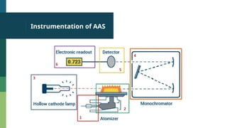
Atomic Absorption Spectroscopy
Smita P. Shelke,
Assistant Professor,
Department of Pharmaceutical Chemistry,
GES’s Sir Dr.M.S.Gosavi College of Pharmaceutical Education and Research,
Nashik-05.(Maharashtra)
Introduction
▪ AAS is an analytical technique used to determine how
much of certain elements are in a sample.
▪ Introduced in 1955 by Alan Walsh in Australia.
Introduction
Elements in pink can be detected by AAS
Principle
 It uses the principle that atoms (and ions) can absorb
light at a specific, unique wavelength.
 When this specific wavelength of light is provided, the
energy (light) is absorbed by the atom.
 Electrons in the atom move from the ground state to an
excited state.
 The amount of light absorbed is measured and the
concentration of the element in the sample can be
calculated.
Principle
o In AAS, a solution containing the analyte is introduced
into a flame.
o The flame converts samples into free ground state atoms
that can be excited.
o A lamp emitting light at a wavelength specific to the
atoms is passed through the flame, and as the light
energy is absorbed, the electrons in the atoms are
elevated to an excited state.
o The Beer Lambert law applied to energy absorbed.
Principle
The Beer Lambert Law defines the relationship between the
concentration and absorption of an absorbing species.
A = E* b * c
Where:
A is the absorbance Abs is measured by the AAS.
E is the characteristic absorption of element of interest.
b is the pathlength.
c is the determined concentration of the element.
Instrumentation
AAS
Instrumentation of AAS
Components of AAS
 A sample introduction system
 Flame atomization system : The burner (flame) and its associated gas
supplies: air-acetylene or nitrous oxide-acetylene
 Non flame atomization - GRAPHITE TUBE ATOMIZER
 A light source, the Hollow Cathode Lamp (HCL)
 A Monochromator (the optical components inside the box in the
diagram)
 An optical detector (photomultiplier tube or PMT)
 Computerized instrument control, data collection, and analysis.
Reference: https://www.agilent.com/en/support/atomic-spectroscopy/atomic-absorption/flame-atomic-
Sample introduction system
 The liquid sample is transported via capillary tubing into the
nebulizer. The pneumatic nebulizer makes use of the Venturi
effect.
 The fluid then impacts a glass bead to create a fine spray of
droplets, known as an aerosol.
 Larger droplets drain to waste, while the fine aerosol is passed
up into the spray chamber.
Flame AAS: Burners
The burner converts the aerosol/gas mixture created by the spray
chamber and nebulizer, into free, ground state atoms.
There are two common gas mixtures that are burnt to fuel the
flame. They are air-acetylene and nitrous oxide-acetylene.
Air-acetylene: Producing a flame around 2300 °C, is suitable for
most elements.
Nitrous oxide-acetylene: Producing a flame 2700 °C, creates a
more reducing environment, suitable for elements that are prone to
form oxides.
Flame AAS: Burners
There are four main stages the aerosolized analyte solution goes through in
a flame AAS burner. They are:
1.Desolvation, or drying. The solvent is evaporated, resulting in dry
nanoparticles of the sample remaining.
2. Vaporization. The particles are converted to the gaseous phase
3. Atomization. The key stage at which the population of ground state,
freely dissociated atoms is created. Ground state atoms are the target for
AAS analysis.
4. Ionization. Some, but not all, free atoms will be converted to ions. This
will depend on the flame conditions (gas mix) and the ionization potential of
the analytes on solution.
Non Flame: Graphite furnac
Using electro thermal heating, a graphite tube provides a small,
contained area for atomization.
The high temperature capabilities and containment of the sample
allows for complete atomization.
Graphite furnace AAS (GF-AAS) is able to detect some elements
down to ppb levels.
The graphite tube (A) is around 20 mm long. A hole in the center of
the tube allows sample to be placed inside. The open ends of the
tube allow light to pass through the atomized sample. (B) Cutaway
of the graphite tube showing the platform design, where the
sample is deposited.
Non Flame: Graphite furnac
Light source
Hollow Cathode Lamp (HCL)
 HCL is the most common light source.
 Filled with an inert ‘filler’ gas at low pressure, usually argon or
neon.
 A metal cathode, coated in the element of interest, is
positioned opposite an anode.
 A high voltage is applied, across the two electrodes, which
ionizes the filler gas accelerating ions toward the cathode.
 The cathode is bombarded by these ions with enough energy
that metal atoms from the cathode material are ejected or
“sputtered” creating an atom plume.
 Characteristic wavelengths of that specific metal is emitted.
Monochromator
• A monochromator is used to isolate a single resonance emission
line.
It consists of
• Entrance slit: It effectively confines the source radiation to narrow
beam.
• Internal mirrors: These direct the light towards dispersing element.
• Dispersing element: Prism and Gratings
• Exit slit: The wavelength selected for analytical measurement is
focused onto the exit slit where it will then pass to the optical
detector for measurement.
Detector
 The most used detector in AAS is the photomultiplier tube (PMT).
 The photomultiplier tube takes the light from the monochromator and
converts it to an electrical signal. The series of dynodes can amplify the
signal by 100 million times.
Computerized instrument
control
 The information collected by the instrument is fed to the
controlling computer.
 Specialized instrument control software calculates the
concentration of each element in the sample, using the
calibration that was performed before the sample
analysis.
Interferences in AAS
1. SPECTRAL INTERFERENCES
▪ SCATTERING
▪ BACKGROUND ABSORPTION
2. CHEMICAL INTERFERENCES
▪ DISSOCIATION
▪ IONIZATION INTERFERENCES
3. MATRIX INTERFERENCES
Reference: http://delloyd.50megs.com/MOBILE/AAinterfer.html
SPECTRAL INTERFERENCES
Spectral interference is caused by radiation overlap of absorption
line due to emissions from another element or compound.
Solutions: Use alternate wavelength. Use smaller slit width. Use blank.
 Scattering interference arise when particulate matter from
flame atomization scatter the incident radiation from the
source.
Incomplete combustion of organic materials which give rise to
molecular species that exhibit broad band spectra.
Solutions: Use blank.
SPECTRAL INTERFERENCES
BACKGROUND ABSORPTION
 Background absorption is caused by light absorption due to
unvaporised solvent droplets in flame.
 It is also caused by absorption of unknown molecular species in
flame.
Solutions:A deuterium source lamp is used for background correction
which comes already fitted into the Atomic absorption instrument
CHEMICAL INTERFERENCES
Chemical interference occurs when an analyte is not totally decomposed
in flame. There is less atoms present, and therefore a reduced
absorbance of the analyte.
Solutions: Use Hotter flame Use Releasing agent (reacts with the
interferent)
DISSOCIATION
Dissociation occurs when metal oxides and hydroxides dissociate in
flame to release the metal atom.
IONIZATION INTERFERENCES
Ionization interference affects Gp 1 and 2 only. These include Ba, Ca, Sr,
MATRIX
INTERFERENCES
 Matrix interference is a physical interference, and can either
suppress or enhance absorbance signal of analyte.
 It occurs when components of sample matrix other than the
analyte react to form molecular species and sample
background.
 The detector picks up unspecified signals from sample matrix
that do not match the absorbance line of the analyte. This
results in spurious readings that can affect quantitative and
qualitative analysis.
Applications of AAS
1. Agriculture – analyzing soil and plants for minerals necessary for
growth
2. Chemical – analyzing raw chemicals as well as fine chemicals
3. Environmental Study – determination of heavy metals in water, soil, and
air
4. Food Industry – quality assurance and testing for contamination
5. Forensics – substance identification
AAS Spectrum
AAS Spectrum
Quantitative AAS

Atomic Absorption Spectrocopy: Atomic spectroscopy

  • 1.
    Atomic Absorption Spectroscopy SmitaP. Shelke, Assistant Professor, Department of Pharmaceutical Chemistry, GES’s Sir Dr.M.S.Gosavi College of Pharmaceutical Education and Research, Nashik-05.(Maharashtra)
  • 2.
    Introduction ▪ AAS isan analytical technique used to determine how much of certain elements are in a sample. ▪ Introduced in 1955 by Alan Walsh in Australia.
  • 3.
    Introduction Elements in pinkcan be detected by AAS
  • 4.
    Principle  It usesthe principle that atoms (and ions) can absorb light at a specific, unique wavelength.  When this specific wavelength of light is provided, the energy (light) is absorbed by the atom.  Electrons in the atom move from the ground state to an excited state.  The amount of light absorbed is measured and the concentration of the element in the sample can be calculated.
  • 5.
    Principle o In AAS,a solution containing the analyte is introduced into a flame. o The flame converts samples into free ground state atoms that can be excited. o A lamp emitting light at a wavelength specific to the atoms is passed through the flame, and as the light energy is absorbed, the electrons in the atoms are elevated to an excited state. o The Beer Lambert law applied to energy absorbed.
  • 6.
    Principle The Beer LambertLaw defines the relationship between the concentration and absorption of an absorbing species. A = E* b * c Where: A is the absorbance Abs is measured by the AAS. E is the characteristic absorption of element of interest. b is the pathlength. c is the determined concentration of the element.
  • 7.
  • 8.
  • 9.
    Components of AAS A sample introduction system  Flame atomization system : The burner (flame) and its associated gas supplies: air-acetylene or nitrous oxide-acetylene  Non flame atomization - GRAPHITE TUBE ATOMIZER  A light source, the Hollow Cathode Lamp (HCL)  A Monochromator (the optical components inside the box in the diagram)  An optical detector (photomultiplier tube or PMT)  Computerized instrument control, data collection, and analysis. Reference: https://www.agilent.com/en/support/atomic-spectroscopy/atomic-absorption/flame-atomic-
  • 10.
    Sample introduction system The liquid sample is transported via capillary tubing into the nebulizer. The pneumatic nebulizer makes use of the Venturi effect.  The fluid then impacts a glass bead to create a fine spray of droplets, known as an aerosol.  Larger droplets drain to waste, while the fine aerosol is passed up into the spray chamber.
  • 11.
    Flame AAS: Burners Theburner converts the aerosol/gas mixture created by the spray chamber and nebulizer, into free, ground state atoms. There are two common gas mixtures that are burnt to fuel the flame. They are air-acetylene and nitrous oxide-acetylene. Air-acetylene: Producing a flame around 2300 °C, is suitable for most elements. Nitrous oxide-acetylene: Producing a flame 2700 °C, creates a more reducing environment, suitable for elements that are prone to form oxides.
  • 12.
    Flame AAS: Burners Thereare four main stages the aerosolized analyte solution goes through in a flame AAS burner. They are: 1.Desolvation, or drying. The solvent is evaporated, resulting in dry nanoparticles of the sample remaining. 2. Vaporization. The particles are converted to the gaseous phase 3. Atomization. The key stage at which the population of ground state, freely dissociated atoms is created. Ground state atoms are the target for AAS analysis. 4. Ionization. Some, but not all, free atoms will be converted to ions. This will depend on the flame conditions (gas mix) and the ionization potential of the analytes on solution.
  • 13.
    Non Flame: Graphitefurnac Using electro thermal heating, a graphite tube provides a small, contained area for atomization. The high temperature capabilities and containment of the sample allows for complete atomization. Graphite furnace AAS (GF-AAS) is able to detect some elements down to ppb levels. The graphite tube (A) is around 20 mm long. A hole in the center of the tube allows sample to be placed inside. The open ends of the tube allow light to pass through the atomized sample. (B) Cutaway of the graphite tube showing the platform design, where the sample is deposited.
  • 14.
  • 15.
    Light source Hollow CathodeLamp (HCL)  HCL is the most common light source.  Filled with an inert ‘filler’ gas at low pressure, usually argon or neon.  A metal cathode, coated in the element of interest, is positioned opposite an anode.  A high voltage is applied, across the two electrodes, which ionizes the filler gas accelerating ions toward the cathode.  The cathode is bombarded by these ions with enough energy that metal atoms from the cathode material are ejected or “sputtered” creating an atom plume.  Characteristic wavelengths of that specific metal is emitted.
  • 16.
    Monochromator • A monochromatoris used to isolate a single resonance emission line. It consists of • Entrance slit: It effectively confines the source radiation to narrow beam. • Internal mirrors: These direct the light towards dispersing element. • Dispersing element: Prism and Gratings • Exit slit: The wavelength selected for analytical measurement is focused onto the exit slit where it will then pass to the optical detector for measurement.
  • 17.
    Detector  The mostused detector in AAS is the photomultiplier tube (PMT).  The photomultiplier tube takes the light from the monochromator and converts it to an electrical signal. The series of dynodes can amplify the signal by 100 million times.
  • 18.
    Computerized instrument control  Theinformation collected by the instrument is fed to the controlling computer.  Specialized instrument control software calculates the concentration of each element in the sample, using the calibration that was performed before the sample analysis.
  • 19.
    Interferences in AAS 1.SPECTRAL INTERFERENCES ▪ SCATTERING ▪ BACKGROUND ABSORPTION 2. CHEMICAL INTERFERENCES ▪ DISSOCIATION ▪ IONIZATION INTERFERENCES 3. MATRIX INTERFERENCES Reference: http://delloyd.50megs.com/MOBILE/AAinterfer.html
  • 20.
    SPECTRAL INTERFERENCES Spectral interferenceis caused by radiation overlap of absorption line due to emissions from another element or compound. Solutions: Use alternate wavelength. Use smaller slit width. Use blank.  Scattering interference arise when particulate matter from flame atomization scatter the incident radiation from the source. Incomplete combustion of organic materials which give rise to molecular species that exhibit broad band spectra. Solutions: Use blank.
  • 21.
    SPECTRAL INTERFERENCES BACKGROUND ABSORPTION Background absorption is caused by light absorption due to unvaporised solvent droplets in flame.  It is also caused by absorption of unknown molecular species in flame. Solutions:A deuterium source lamp is used for background correction which comes already fitted into the Atomic absorption instrument
  • 22.
    CHEMICAL INTERFERENCES Chemical interferenceoccurs when an analyte is not totally decomposed in flame. There is less atoms present, and therefore a reduced absorbance of the analyte. Solutions: Use Hotter flame Use Releasing agent (reacts with the interferent) DISSOCIATION Dissociation occurs when metal oxides and hydroxides dissociate in flame to release the metal atom. IONIZATION INTERFERENCES Ionization interference affects Gp 1 and 2 only. These include Ba, Ca, Sr,
  • 23.
    MATRIX INTERFERENCES  Matrix interferenceis a physical interference, and can either suppress or enhance absorbance signal of analyte.  It occurs when components of sample matrix other than the analyte react to form molecular species and sample background.  The detector picks up unspecified signals from sample matrix that do not match the absorbance line of the analyte. This results in spurious readings that can affect quantitative and qualitative analysis.
  • 24.
    Applications of AAS 1.Agriculture – analyzing soil and plants for minerals necessary for growth 2. Chemical – analyzing raw chemicals as well as fine chemicals 3. Environmental Study – determination of heavy metals in water, soil, and air 4. Food Industry – quality assurance and testing for contamination 5. Forensics – substance identification
  • 25.
  • 26.
  • 27.