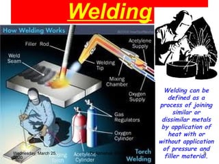
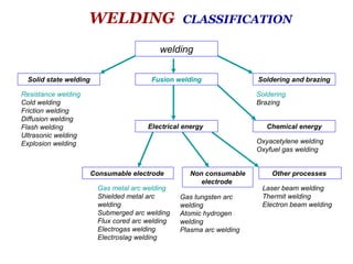
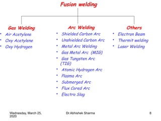
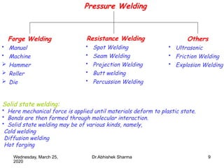
11Wednesday, March 25,
2020
Dr.Abhishek Sharma
By
Dr. Abhishek Sharma
Metal Joining (Welding)
Unit - IV
GL BAJAJ INSTITUTE OF TECHONOLOGY & MANAGEMENT
2
Welding
Welding can be
defined as a
process of joining
similar or
dissimilar metals
by application of
heat with or
without application
of pressure and
filler material.
Wednesday, March 25,
2020
Dr.Abhishek Sharma
Wednesday, March 25,
2020
Dr.Abhishek Sharma 3
• Until the end of the 19th century, the only welding process was forge welding.
• Arc welding and oxyfuel welding were among the first processes to develop
during the 1800s, and resistance welding followed soon after.
• Welding technology advanced quickly during the early 20th century as World
War I and World War II drove the demand for reliable and inexpensive joining
methods.
• Following the wars, several modern welding techniques were developed,
including manual methods like shielded metal arc welding, now one of the most
popular welding methods, as well as semi-automatic and automatic processes
such as gas metal arc welding, submerged arc welding and flux-cored arc
welding.
• Developments continued with the invention of laser beam welding and electron
beam welding in the latter half of the century.
• Robot welding is becoming more commonplace in industrial settings today.
welding
Solid state welding Soldering and brazingFusion welding
Electrical energy Chemical energy
Other processesNon consumable
electrode
Consumable electrode
Resistance welding
Cold welding
Friction welding
Diffusion welding
Flash welding
Ultrasonic welding
Explosion welding
Gas metal arc welding
Shielded metal arc
welding
Submerged arc welding
Flux cored arc welding
Electrogas welding
Electroslag welding
Gas tungsten arc
welding
Atomic hydrogen
welding
Plasma arc welding
Oxyacetylene welding
Oxyfuel gas welding
Laser beam welding
Thermit welding
Electron beam welding
Soldering
Brazing
WELDING CLASSIFICATION
5
Advantages of Welding over other joints:
• Lighter structures with higher joint strength can be easily and rapidly made.
• Thus are cheaper.
• welded joints have higher corrosion resistance.
• Are fluid tight for tanks and vessels.
• Can be easily and economically altered.
• Variety of joints are possible.
Disadvantages:
• Produces waves of longer wavelength than X and γ rays.
• These are made up of visible light rays, infra red rays and ultraviolet rays.
• Ultraviolet rays can cause burns to corners and eye retina.
• Infrared rays have longer wavelength and produce heat when they strike and are
absorbed into surface.
• For protection, welders should wear welding jackets made of leather, denim,
boot.
Wednesday, March 25,
2020
Dr.Abhishek Sharma
6
Solid Phase or plastic or pressure welding:
• Clean faces of component are brought into intimate contact to produce a metallic
bond with or without application of heat.
• Here application of pressure is essential to produce the plastic flow.
• Now a days means to weld dissimilar metals have been found out.
• Welding gives 100% strength of the joint and is very easy process.
Weldability:
• Is capacity of being welded into inseparable joints having specific
properties like definite weld strength, proper structure etc.
• Weldability is based on criterion like ease of welding and weld quality.
Thus welding can be defined as a process of joining
similar or dissimilar metals by application of heat
with or without application of pressure and addition
of filler material.
Welding can be categorized in following two wide groups:
1. Fusion or Non Pressure Welding
2. Plastic or Pressure Welding
Wednesday, March 25,
2020
Dr.Abhishek Sharma
7
Fusion welding
• Process of joining two metal pieces by application of heat.
• Parts to be joined are placed together, heated (often with addition of filler
metal), until they melt and solidify on cooling.
• Following methods could be used to develop heat:
 Combustion of fuel gas with oxygen.
 Electric arc.
Plasma arc, electron beam, laser beam.
• Sometimes pressure is also applied with heat to have better joining section.
• Fillers are used to attain additional strength of the joint.
• Ways of applying pressure can be hammering, rolling or using dies.
• In fusion welding metals to be joined are brought to fluid state without
application of pressure and joined by filler material.
Wednesday, March 25,
2020
Dr.Abhishek Sharma
8
Fusion welding
Gas Welding
• Air Acetylene
• Oxy Acetylene
• Oxy Hydrogen
Arc Welding
• Shielded Carbon Arc
• Unshielded Carbon Arc
• Metal Arc Welding
• Gas Metal Arc (MIG)
• Gas Tungsten Arc
(TIG)
• Atomic Hydrogen Arc
• Plasma Arc
• Submerged Arc
• Flux Cored Arc
• Electro Slag
Others
• Electron Beam
• Thermit welding
• Laser Welding
Wednesday, March 25,
2020
Dr.Abhishek Sharma
9
Pressure Welding
Forge Welding
• Manual
• Machine
 Hammer
 Roller
 Die
Resistance Welding
• Spot Welding
• Seam Welding
• Projection Welding
• Butt welding
• Percussion Welding
Others
• Ultrasonic
• Friction Welding
• Explosion Welding
Solid state welding:
• Here mechanical force is applied until materials deform to plastic state.
• Bonds are then formed through molecular interaction.
• Solid state welding may be of various kinds, namely,
Cold welding
Diffusion welding
Hot forging
Wednesday, March 25,
2020
Dr.Abhishek Sharma
10
Gas Welding:
• Here heat necessary to produce the fusion is obtained by burning some gas
issuing from nozzle of a blow pipe or torch.
• Gas issuing from the nozzle is already mixed with amount of oxygen required to
produce a flame.
• This flame may be chemically oxidizing, neutral or reducing depending on the
requirement of the type of metal or alloy being welded.
Oxy – acetylene welding:
• Gases used are oxygen (O2) and acetylene (C2H2) for producing flame.
• It can be obtained under high pressure (14 MPa and 200C) in cylinders which are
fitted with pressure regulators.
• Acetylene is obtained by dropping lumps of calcium carbide (CaC2) in water.
CaC2 + 2H2O === C2H2 + Ca(OH)2
(Slaked or hydrated lime)
Wednesday, March 25,
2020
Dr.Abhishek Sharma
11
• Oxygen Cylinders are painted black.
• Acetylene cylinders are painted maroon.
• Acetylene must be used at low pressure otherwise it may explode.
Gas Flames
Is phenomenon produced at surface of nozzle tip, where two gases meet and
undergo combustion with evolution of heat and some light.
2C2H2 + 5O2 = 4CO2 + 2H2O + Heat
• Heat produced is approximately 53.38 MJ/m3
of acetylene.
• For complete combustion, ratio of O2 to C2H2 is 2.5 to 1.
• Proportion of oxygen to acetylene can be varied to produce carburizing or
oxidizing or neutral flame.
Neutral flame:
• If O2 and C2H2 are used in equal proportion then incomplete combustion of
acetylene occurs at torch tip.
C2H2 + O2 = 2CO + H2 + Heat Energy
• Subsequently CO and H2 produced burn on coming in contact with atmospheric O2
2CO+O2 = 2CO2 + Heat Energy
2H2 + O2 = 2H2O + Energy
Wednesday, March 25,
2020
Dr.Abhishek Sharma
12
• Thus a type of envelope is formed out of combustion of CO on the inner flame
formed due to incomplete combustion of C2H2.
• Inner white and sharply defined central cone referred as luminous cone is at a
temperature around 3300o
C.
• No oxidation takes place, thus widely used.
• Used for welding all metals like ferrous materials, Cu and Aluminum except
brass.
Carburizing or reducing flame:
• If proportion of acetylene is increased then carburizing flame is achieved.
• Bright luminous inner zone of the flame is at temperature of 31500C.
Oxidizing Flame:
• Is obtained by increasing the oxygen flow rate.
• Here inner pointed cone is at a temperature of about 35000
C
Wednesday, March 25,
2020
Dr.Abhishek Sharma
13
Equipments:
1. O2 cylinders:
2. C2H2 cylinders:
3. Regulators:
• When acetylene is fully filled it has a
pressure of 250 psi and oxygen cylinder
has 2200 psi.
• Regulator is used to regulate this
pressure and lower it to make usable at
desired working pressure in the torch.
• Single stage and two stage regulators
are used.
4. Welding Hoses:
• Cylinders, torches and regulators are
connected by rubber hoses.
5. Check Valve:
• Mixing of fuel and O2 for combustion should occur in torch mixer or torch tip.
• Check valve is installed b/w hoses and torch to prevent back flow thus avoids combustion in hoses
Wednesday, March 25,
2020
Dr.Abhishek Sharma
14
6. Welding torches:
• The assembly consists of handle, O2 and fuel gas valves and mixing chamber.
• Welding tips or cutting attachment may be used with handle.
• O2 and fuel gas flow through tubes inside the handle.
• These gases mix in mixing chamber or at tip.
7. Welding and cutting tips:
The molten pool is generally supplied with additional metal called filler. Filler
material depends upon the metals to be welded.
A stream of oxygen is then trained on the metal, and metal burns in that oxygen
and then flows out of the cut as an oxide slag.
Wednesday, March 25,
2020
Dr.Abhishek Sharma
Wednesday, March 25,
2020
Dr.Abhishek Sharma 15
Arc Welding
16
Arc Welding
• Heat required to melt the base metal is obtained from an arc.
• An arc is established b/w metal electrode and workpiece.
• Heat is liberated at arc terminals which melts the base metal at the point of
contact.
• Filler material is added to the surface of metal to attain additional strength.
• Temperature of arc is around 40000
C and maximum up to 55000
C.
• This heat causes a small pool of metal to melt in the work.
• For filler material welding rod is used which is melted by heat of arc.
• This melted filler material is deposited into the small pool of molten metal.
• Arc agitates the molten metal in the pool causing base and added metal to mix
thoroughly, which forms a sound joint on cooling.
• Properties and composition of a weld should match those of the base metal
closely.
• Thus different types of rods have been developed for welding of different
metals
• Electrodes can be flux coated or bare.
• Electrode coatings consist of a number of different compounds, including
calcium fluoride, cellulose, iron powder and TiO2
Wednesday, March 25,
2020
Dr.Abhishek Sharma
17
This flux is intended to perform following functions:
1. Produce gas which provides a shield around the arc to protect it from the atmosphere.
2. Forms slag by mixing with impurities of the molten metal and thus refines metal.
3. Slag being less dense floats over molten metal surface and protects the molten metal pool
from oxidation. This slag is easily chipped off with chipping hammer at the end of the
process.
• Arc is created by low voltage, high current supply.
• Arc initiation voltage: 60 to 100V and arc maintenance voltage 25 to 40V.
Wednesday, March 25,
2020
Dr.Abhishek Sharma
18
Arc Welding Equipments:
1. Electric supply source: Arc can be struck either with AC or DC source.
• Arc initiation voltage may vary from 60 to 100V and arc maintenance voltage
ranges between 15 to 40V.
• Current for welding may range from 30 to 600 amperes.
• Source AC or Dc should have low voltage and high current characteristics.
• Either DC generator or AC alternator with step down transformer is used.
Wednesday, March 25,
2020
Dr.Abhishek Sharma
 Arc can be described as a stream of incandescent metallic vapor which acts
a conducting medium for electric current from one terminal to other to
complete the circuit
A selenium rectifier is used to convert AC to DC.
2. Electrode holder
3. Welding cables
4. Ground clamps.
5. Welding electrodes.
6. Welding helmet and hand shield.
7. Hand gloves and aprons, Chipping hammer, wire brush etcetera.
19
Polarity in Arc Welding:
• In AC heat generated at each pole is same because of reversal of current.
• Thus changing over connections to electrode does not effect.
• In DC positive pole of arc becomes hottest.
• If electrode is at negative of generator and workpiece at positive it is called
straight polarity.
• Reverse polarity vice versa.
• Penetration is less with uncoated electrode with reverse polarity.
Electrodes in arc welding:
1. Bare Electrodes:
• Have limited application as during welding they are exposed to O2 and N2 of air.
• This forms non metallic constituents which are trapped in rapidly solidifying
weld metal.
• Thus strength and ductility of weld metal reduces and quality obtained is also
poor.
• Used for welding wrought iron and mild steel.
• Also used where less skill is required like automatic and semi automatic welding.
Wednesday, March 25,
2020
Dr.Abhishek Sharma
20
Electrodes can either be consumable or inconsumable type.
2. Coated Electrodes:
• Coating eliminates undesirable oxides and prevent their formation.
• Heavy coated electrodes are most important and used majorly.
• Type of flux coating depends on weld metal composition.
• Slag produced should have lower density than the base metal.
• Coating helps in striking arc and enables it to be stable.
• It also provides gaseous shield, preventing oxidation of molten weld metal pool.
• Coating also replenish elements like C, Mn, Ni etc which are partially lost during
combustion.
• Slag reduces cooling rate of joint and helps in refining of its grain structure.
• Ingredients of flux are like asbestos, mica, silica, steelite, fluorspar (fluorites),
titanium oxide, iron oxide, magnesium carbonate, calcium carbonate and alumina.
• Alloying elements are received from ferromanganese, potassium titanate.
• Light to medium coated electrodes have coating between 10 to 55% of total
diameter if die coated electrode.
Wednesday, March 25,
2020
Dr.Abhishek Sharma
21
Designation of electrodes:
Electrode specified with 6 digits as per IS coding:
• First Digit: (1 to 8) Each numbers corresponds to covering (flux) on electrode.
• Second Digit: (1 to 6) Represents position of welding.
• Third Digit: (0 to 7) Number represents particularly suitable current condition.
• Fourth Digit: (1 to 8) Minimum tensile strength of the weld metal.
• Fifth Digit: (1 to 5): % elongation of deposited weld metal in tensile testing.
• Sixth Digit: (1 to 5) Minimum impact Load of the weld metal.
Wednesday, March 25,
2020
Dr.Abhishek Sharma
22
Submerged Arc Welding:
Automatic form of SMAW and can be used in straight line joining of metals.
• Bare metallic, copper plated electrode in form of long coiled wire is used .
• Copper used to ensure low resistance electrical contact between wire & contact shoe. Arc is
created between electrode and workpiece.
• The arc, the end of the electrode and molten weld pool are submerged in a finely divided
granulated powdered flux containing appropriate deoxidizers, cleansers, and fluxing elements.
• Flux powder is fed from hopper.
• Tube from hopper spreads powder continuously in front of electrode in the line of weld.
Wednesday, March 25,
2020
Dr.Abhishek Sharma
23
• Weld beds produced are exceptionally smooth.
• Un melted flux is removed by suction system and can be reused.
• Process limited to flat welding.
• Uses high current ranging between 300 to 400 amp.
Advantages:
• Use of high current gives high deposition rates.
• Deep weld penetration.
• Process thermally efficient.
• Weld beads are extremely smooth.
• Used in rebuilding and hard surfacing rolls.
Disadvantages:
• Weld cannot be seen, thus difficult.
• Limited to flat positions only.
• Overhead welding is impractical.
Wednesday, March 25,
2020
Dr.Abhishek Sharma
24
Gas Metal Are Welding or Metal Inert Gas Welding:
• Semi automatic or automatic arc welding process.
• Continuous and consumable wire electrode and a shielding Argon gas are fed
through a welding gun.
• Used in automatic industry, tank, ship and aircraft building.
• Semi inert gases like CO2 or Ar + He also used now a days to reduce process
cost.
• A fixed relationship b/w rate of wire burn off and welding current exist.
Wednesday, March 25,
2020
Dr.Abhishek Sharma
25
• Thus when wire feed rate is fixed, welding machine gives necessary current to
maintain arc.
• Current range 100 to 400 A, which depends on diameter of wire and speed of
melting of wire.
Equipments:
• Welding gun and wire feed unit.
• Power supply
• Electrode
• Shielding Gas
Metal transfer in MIG welding takes place majorly by following four methods:
1. Globular:
• Uses CO2, a less expensive shielding gas.
• Produces high heat, thus high deposition rate.
• During welding a ball of molten metal from the electrode tends to build up on
end of electrode, which is irregular in shape and falls in weld pool.
• Thus producing poor weld surface and spatters.
• Electrode wire used are larger because of high heat produced.
Limitations of MIG welding:
• Irregular wire feed.
• Burn back
• Unstable arc
• Heavily oxidized weld deposit.
Wednesday, March 25,
2020
Dr.Abhishek Sharma
26
2. Short Circuiting:
• Uses CO2.
• Electrode wire is smaller and thus current is lower.
• Thus heat input is low, making possible to weld thinner materials.
• Here molten droplets formed on tip of electrode bridge the gap between
electrode and weld pool, causing short circuit and arc extinguish.
• Arc soon gets reignited as the surface tension of weld pool pulls the molten
metal off the electrode tip.
• This process is repeated about 100 times in second, making arc appear constant
to human eye.
• Better weld quality is received, since less spatter are formed.
• Slower process than globular welding.
3. Spray:
• Thick electrode used.
• Here dia of molten droplets is lesser than that of electrode unlike globular.
• droplets rapidly pass along stable arc from electrode to workpiece, eliminating
spatter and resulting high weld quality.
• High value of current and voltage is required, causing high heat input and large
weld area and HAZ.
Wednesday, March 25,
2020
Dr.Abhishek Sharma
27
4. Pulsed Spray:
• It is based on principle of spray transfer.
• Pulsing current is used to melt the filler wire and allow one small molten droplet
to fall with each pulse.
• Pulses allow average current to be lower, decreasing overall heat input and thus
decreasing size of weld pool and HAZ.
• Can be employed for making thin work piece.
• Pulse provide stable arc and no spatter.
• Shield gas should be Ar; CO2 should be least used.
• Special power source, capable of providing pulsated current is required, having
frequency 30 to 400 pulses per second.
Defects of GMAW:
• Undercutting, Incomplete fusion, Incomplete joint penetration, porosity
• Excessive melt through, weld metal crack, HAZ cracks.
Advantages of GMAW:
• Welding rate is very high with good quality weld.
• No slag formation, to be chipped off.
• Versatile process, permits welding in all directions.
Limitations:
• Irregular wire feed rate.
• Burn back and unstable
arc
Wednesday, March 25,
2020
Dr.Abhishek Sharma
28
Advantages
• Superior weld quality.
• Filler may or may not be used.
• Precise control of variables.
• No cleaning required as no flux
produced
• Welding can be done in all positions.
Disadvantages
• Lower deposition rates.
• More costly.
• Excessive electrode deterioration.
• Skilled worker needed as arc
initiation is difficult.
• Not suited for welding heavier metal.
Atomic Hydrogen Welding:
• Here two tungsten electrodes are used.
• Arc is struck b/w these two electrodes.
• These electrodes are contained in body of the torch.
• Each electrode is surrounded by stream of hydrogen gas.
• Size of tungsten electrode is dependent on rate of heat input required.
• Molecules of H2 gas are broken into atoms as soon as they enter the arc, by
absorbing the heat from the arc.
• These atoms recombine into molecules outside the arc and tremendous amount
of heat of order of 61000
C is liberated.
Wednesday, March 25,
2020
Dr.Abhishek Sharma
29
Tungsten Inert Gas
Welding (TIG)
Wednesday, March 25,
2020
Dr.Abhishek Sharma
30
Tungsten Inert Gas Welding (TIG)
• Tungsten electrode is used as it can withstand high temperatures (4000o
C).
• Electrode is surrounded by a nozzle which conducts shielding gas (Ar or He).
• Electrode is non consumable and separate filler material may be used.
• Tungsten alloyed with Zirconia is used to stabilize the arc and provide easy start.
• Since it can be mechanized easily and gives high quality weld, thus used in precision work like
atomic energy and instrument industries.
• A typical TIG welding set up consists of tungsten electrode mounted in centre of
welding torch.
Wednesday, March 25,
2020
Dr.Abhishek Sharma
31
• Inert gas is supplied to welding zone through annular path surrounding tungsten electrode to
effectively displace atmosphere around weld puddle.
• Tubing for water cooling of electrodes is provided.
• Torches carrying current of 100A are usually water cooled.
• DC straight polarity or DCEN, as well as DCRP may be used.
• AC supply can also be used.
• DCEN provides deep penetration and faster welding.
• Dcep provides wide weld pool and shallow penetration thus used for thin w/p.
Defects in TIG:
• Under cutting, weld metal cracks.
• Tungsten inclusion
• Porosity.
• HAZ cracks
Wednesday, March 25,
2020
Dr.Abhishek Sharma
32
Resistance Welding:
• Resistance welding is accomplished when current is caused to flow through electrode tips and
the separate pieces of metal to be joined.
• The resistance of the base metal to electrical current flow causes localized heating in the joint,
and the weld is made.
• The weld is made by a combination of heat, pressure and time.
• The pressure exerted by the tongs and electrode tips, through which the current flows, holds
the parts to be welded in intimate contact before, during and after the welding current time
cycle
• The required amount of time current flows in the joint is determined by material thickness and
the type, the amount of current flowing, and the cross sectional area of welding tip contact
surface.
• In resistance welding actual nugget is
formed internally, unlike that in other
welding methods like TIG.
Wednesday, March 25,
2020
Dr.Abhishek Sharma
33
• Spot welding in particular has been used extensively in the automotive industry.
• For the joining of steel and in the aerospace industry for airframe components in aluminum
alloys.
• Seam welding is used in the production of thin sheet, leak-tight containers such as fuel tanks.
Principle of Resistance welding:
• The basic formula for heat generation may be stated:
H = I2
Rt
H is Heat, I2
is welding current squared and t is the time for which current flows.
Spot Welding
• The resistance spot weld nugget is formed when the interface of the weld joint is heated due to
the resistance of the joint surfaces to electrical current flow.
• The current must flow or the weld cannot be made.
• Pressure of electrode tips on the workpiece holds the part in close and intimate contact during
the making of the weld.
Spot Welding Time Cycle:
• SQUEEZE TIME − Time between pressure application and weld.
• HEAT OR WELD TIME − Actual Welding Time.
• HOLD TIME − Time that pressure is maintained after weld is made.
• OFF TIME − Electrodes separated to permit moving of material for next spot.
Wednesday, March 25,
2020
Dr.Abhishek Sharma
34Wednesday, March 25,
2020
Dr.Abhishek Sharma
35
 Copper is the base metal normally used for resistance spot welding tips.
 The purpose of electrode tips is to conduct the welding current to the workpiece.
 To be the focal point of the pressure applied.
 To the weld joint, to conduct heat from the work surface, and to maintain their integrity of
shape and characteristics of thermal and electrical conductivity
 under working conditions.
 Electrode tips are usually made of copper and its alloys.
Resistance Welding Machines:
 AC or DC supply may be used.
 The frame solutions for resistance welding machines can vary greatly.
 In larger welding units and automated production, welding force is created by means of
pneumatic and hydraulic cylinders.
 The cooling of transformers and contactors is usually separate from the other cooling circuit.
 Equipment manufacturers usually state the minimum cooling water circulation.
 Inadequate cooling damages the heat balance of the joint and wears the electrodes quickly.
Wednesday, March 25,
2020
Dr.Abhishek Sharma
36
Seam Welding
 Seam Welding replaces spot welding for producing continuous leak proof joints for use in
sheet metal containers like petrol tanks etc.
 In practice it is a continuous type of spot welding, where spot welds overlap each other to the
desired extent.
 Electrodes used are in form of copper wheels or rollers.
 One or both the wheels are powered.
 Pressure is applied in the same way as in spot welding.
 For producing gas tight seam, the welds should overlap 15 to 20% of nugget dia.
 While for maximum strength overlap dia should be 40 to 50%.
 Size of nugget depends on weld time for given welding speed and current and the amount of
overlap depends upon the off time.
 As the electrodes rotate, the work is moved b/w them and current is supplied in pulses during
the weld time.
 Weld time is adjusted to be long enough to produce a spot weld in a metal of given thickness
and desired overlap.
Wednesday, March 25,
2020
Dr.Abhishek Sharma
37
• These molecules also form the blanket avoiding oxygen.
• Normally AC is used, since better regulation is possible and reversing polarity equalizes
electrode deterioration.
• It gives high heat concentration.
• Can be used for alloy welding , H2 acts as shield thus no shielding gas required.
Wednesday, March 25,
2020
Dr.Abhishek Sharma
38
Electro Slag Welding:
• Used to weld seams of thick section in single pass.
• Plates to be welded are placed in a vertical position, so that molten metal is delivered
progressively to vertical gap.
• 2-3 electrodes are used which are fed vertically.
• Powdered granular flux is poured from hopper.
Wednesday, March 25,
2020
Dr.Abhishek Sharma
39Wednesday, March 25,
2020
Dr.Abhishek Sharma
Advantages:
• Automatic process with uniform heating
Disadvantages:
• Used for thick plates only
• In starting arc is created b/w electrode and bottom plate and continued until a sufficient thick
layer of molten slag is formed.
• Arc only initiates melting, thereafter heat is generated by electric resistance offered by the
electrically conducting slag.
• A mechanism for raising the equipment as weld is completed is also used.
• AC power source delivering 1000A is used .
• Shielding gas like CO2 is also used.

As welding

  • 1.
    11Wednesday, March 25, 2020 Dr.AbhishekSharma By Dr. Abhishek Sharma Metal Joining (Welding) Unit - IV GL BAJAJ INSTITUTE OF TECHONOLOGY & MANAGEMENT
  • 2.
    2 Welding Welding can be definedas a process of joining similar or dissimilar metals by application of heat with or without application of pressure and filler material. Wednesday, March 25, 2020 Dr.Abhishek Sharma
  • 3.
    Wednesday, March 25, 2020 Dr.AbhishekSharma 3 • Until the end of the 19th century, the only welding process was forge welding. • Arc welding and oxyfuel welding were among the first processes to develop during the 1800s, and resistance welding followed soon after. • Welding technology advanced quickly during the early 20th century as World War I and World War II drove the demand for reliable and inexpensive joining methods. • Following the wars, several modern welding techniques were developed, including manual methods like shielded metal arc welding, now one of the most popular welding methods, as well as semi-automatic and automatic processes such as gas metal arc welding, submerged arc welding and flux-cored arc welding. • Developments continued with the invention of laser beam welding and electron beam welding in the latter half of the century. • Robot welding is becoming more commonplace in industrial settings today.
  • 4.
    welding Solid state weldingSoldering and brazingFusion welding Electrical energy Chemical energy Other processesNon consumable electrode Consumable electrode Resistance welding Cold welding Friction welding Diffusion welding Flash welding Ultrasonic welding Explosion welding Gas metal arc welding Shielded metal arc welding Submerged arc welding Flux cored arc welding Electrogas welding Electroslag welding Gas tungsten arc welding Atomic hydrogen welding Plasma arc welding Oxyacetylene welding Oxyfuel gas welding Laser beam welding Thermit welding Electron beam welding Soldering Brazing WELDING CLASSIFICATION
  • 5.
    5 Advantages of Weldingover other joints: • Lighter structures with higher joint strength can be easily and rapidly made. • Thus are cheaper. • welded joints have higher corrosion resistance. • Are fluid tight for tanks and vessels. • Can be easily and economically altered. • Variety of joints are possible. Disadvantages: • Produces waves of longer wavelength than X and γ rays. • These are made up of visible light rays, infra red rays and ultraviolet rays. • Ultraviolet rays can cause burns to corners and eye retina. • Infrared rays have longer wavelength and produce heat when they strike and are absorbed into surface. • For protection, welders should wear welding jackets made of leather, denim, boot. Wednesday, March 25, 2020 Dr.Abhishek Sharma
  • 6.
    6 Solid Phase orplastic or pressure welding: • Clean faces of component are brought into intimate contact to produce a metallic bond with or without application of heat. • Here application of pressure is essential to produce the plastic flow. • Now a days means to weld dissimilar metals have been found out. • Welding gives 100% strength of the joint and is very easy process. Weldability: • Is capacity of being welded into inseparable joints having specific properties like definite weld strength, proper structure etc. • Weldability is based on criterion like ease of welding and weld quality. Thus welding can be defined as a process of joining similar or dissimilar metals by application of heat with or without application of pressure and addition of filler material. Welding can be categorized in following two wide groups: 1. Fusion or Non Pressure Welding 2. Plastic or Pressure Welding Wednesday, March 25, 2020 Dr.Abhishek Sharma
  • 7.
    7 Fusion welding • Processof joining two metal pieces by application of heat. • Parts to be joined are placed together, heated (often with addition of filler metal), until they melt and solidify on cooling. • Following methods could be used to develop heat:  Combustion of fuel gas with oxygen.  Electric arc. Plasma arc, electron beam, laser beam. • Sometimes pressure is also applied with heat to have better joining section. • Fillers are used to attain additional strength of the joint. • Ways of applying pressure can be hammering, rolling or using dies. • In fusion welding metals to be joined are brought to fluid state without application of pressure and joined by filler material. Wednesday, March 25, 2020 Dr.Abhishek Sharma
  • 8.
    8 Fusion welding Gas Welding •Air Acetylene • Oxy Acetylene • Oxy Hydrogen Arc Welding • Shielded Carbon Arc • Unshielded Carbon Arc • Metal Arc Welding • Gas Metal Arc (MIG) • Gas Tungsten Arc (TIG) • Atomic Hydrogen Arc • Plasma Arc • Submerged Arc • Flux Cored Arc • Electro Slag Others • Electron Beam • Thermit welding • Laser Welding Wednesday, March 25, 2020 Dr.Abhishek Sharma
  • 9.
    9 Pressure Welding Forge Welding •Manual • Machine  Hammer  Roller  Die Resistance Welding • Spot Welding • Seam Welding • Projection Welding • Butt welding • Percussion Welding Others • Ultrasonic • Friction Welding • Explosion Welding Solid state welding: • Here mechanical force is applied until materials deform to plastic state. • Bonds are then formed through molecular interaction. • Solid state welding may be of various kinds, namely, Cold welding Diffusion welding Hot forging Wednesday, March 25, 2020 Dr.Abhishek Sharma
  • 10.
    10 Gas Welding: • Hereheat necessary to produce the fusion is obtained by burning some gas issuing from nozzle of a blow pipe or torch. • Gas issuing from the nozzle is already mixed with amount of oxygen required to produce a flame. • This flame may be chemically oxidizing, neutral or reducing depending on the requirement of the type of metal or alloy being welded. Oxy – acetylene welding: • Gases used are oxygen (O2) and acetylene (C2H2) for producing flame. • It can be obtained under high pressure (14 MPa and 200C) in cylinders which are fitted with pressure regulators. • Acetylene is obtained by dropping lumps of calcium carbide (CaC2) in water. CaC2 + 2H2O === C2H2 + Ca(OH)2 (Slaked or hydrated lime) Wednesday, March 25, 2020 Dr.Abhishek Sharma
  • 11.
    11 • Oxygen Cylindersare painted black. • Acetylene cylinders are painted maroon. • Acetylene must be used at low pressure otherwise it may explode. Gas Flames Is phenomenon produced at surface of nozzle tip, where two gases meet and undergo combustion with evolution of heat and some light. 2C2H2 + 5O2 = 4CO2 + 2H2O + Heat • Heat produced is approximately 53.38 MJ/m3 of acetylene. • For complete combustion, ratio of O2 to C2H2 is 2.5 to 1. • Proportion of oxygen to acetylene can be varied to produce carburizing or oxidizing or neutral flame. Neutral flame: • If O2 and C2H2 are used in equal proportion then incomplete combustion of acetylene occurs at torch tip. C2H2 + O2 = 2CO + H2 + Heat Energy • Subsequently CO and H2 produced burn on coming in contact with atmospheric O2 2CO+O2 = 2CO2 + Heat Energy 2H2 + O2 = 2H2O + Energy Wednesday, March 25, 2020 Dr.Abhishek Sharma
  • 12.
    12 • Thus atype of envelope is formed out of combustion of CO on the inner flame formed due to incomplete combustion of C2H2. • Inner white and sharply defined central cone referred as luminous cone is at a temperature around 3300o C. • No oxidation takes place, thus widely used. • Used for welding all metals like ferrous materials, Cu and Aluminum except brass. Carburizing or reducing flame: • If proportion of acetylene is increased then carburizing flame is achieved. • Bright luminous inner zone of the flame is at temperature of 31500C. Oxidizing Flame: • Is obtained by increasing the oxygen flow rate. • Here inner pointed cone is at a temperature of about 35000 C Wednesday, March 25, 2020 Dr.Abhishek Sharma
  • 13.
    13 Equipments: 1. O2 cylinders: 2.C2H2 cylinders: 3. Regulators: • When acetylene is fully filled it has a pressure of 250 psi and oxygen cylinder has 2200 psi. • Regulator is used to regulate this pressure and lower it to make usable at desired working pressure in the torch. • Single stage and two stage regulators are used. 4. Welding Hoses: • Cylinders, torches and regulators are connected by rubber hoses. 5. Check Valve: • Mixing of fuel and O2 for combustion should occur in torch mixer or torch tip. • Check valve is installed b/w hoses and torch to prevent back flow thus avoids combustion in hoses Wednesday, March 25, 2020 Dr.Abhishek Sharma
  • 14.
    14 6. Welding torches: •The assembly consists of handle, O2 and fuel gas valves and mixing chamber. • Welding tips or cutting attachment may be used with handle. • O2 and fuel gas flow through tubes inside the handle. • These gases mix in mixing chamber or at tip. 7. Welding and cutting tips: The molten pool is generally supplied with additional metal called filler. Filler material depends upon the metals to be welded. A stream of oxygen is then trained on the metal, and metal burns in that oxygen and then flows out of the cut as an oxide slag. Wednesday, March 25, 2020 Dr.Abhishek Sharma
  • 15.
  • 16.
    16 Arc Welding • Heatrequired to melt the base metal is obtained from an arc. • An arc is established b/w metal electrode and workpiece. • Heat is liberated at arc terminals which melts the base metal at the point of contact. • Filler material is added to the surface of metal to attain additional strength. • Temperature of arc is around 40000 C and maximum up to 55000 C. • This heat causes a small pool of metal to melt in the work. • For filler material welding rod is used which is melted by heat of arc. • This melted filler material is deposited into the small pool of molten metal. • Arc agitates the molten metal in the pool causing base and added metal to mix thoroughly, which forms a sound joint on cooling. • Properties and composition of a weld should match those of the base metal closely. • Thus different types of rods have been developed for welding of different metals • Electrodes can be flux coated or bare. • Electrode coatings consist of a number of different compounds, including calcium fluoride, cellulose, iron powder and TiO2 Wednesday, March 25, 2020 Dr.Abhishek Sharma
  • 17.
    17 This flux isintended to perform following functions: 1. Produce gas which provides a shield around the arc to protect it from the atmosphere. 2. Forms slag by mixing with impurities of the molten metal and thus refines metal. 3. Slag being less dense floats over molten metal surface and protects the molten metal pool from oxidation. This slag is easily chipped off with chipping hammer at the end of the process. • Arc is created by low voltage, high current supply. • Arc initiation voltage: 60 to 100V and arc maintenance voltage 25 to 40V. Wednesday, March 25, 2020 Dr.Abhishek Sharma
  • 18.
    18 Arc Welding Equipments: 1.Electric supply source: Arc can be struck either with AC or DC source. • Arc initiation voltage may vary from 60 to 100V and arc maintenance voltage ranges between 15 to 40V. • Current for welding may range from 30 to 600 amperes. • Source AC or Dc should have low voltage and high current characteristics. • Either DC generator or AC alternator with step down transformer is used. Wednesday, March 25, 2020 Dr.Abhishek Sharma  Arc can be described as a stream of incandescent metallic vapor which acts a conducting medium for electric current from one terminal to other to complete the circuit A selenium rectifier is used to convert AC to DC. 2. Electrode holder 3. Welding cables 4. Ground clamps. 5. Welding electrodes. 6. Welding helmet and hand shield. 7. Hand gloves and aprons, Chipping hammer, wire brush etcetera.
  • 19.
    19 Polarity in ArcWelding: • In AC heat generated at each pole is same because of reversal of current. • Thus changing over connections to electrode does not effect. • In DC positive pole of arc becomes hottest. • If electrode is at negative of generator and workpiece at positive it is called straight polarity. • Reverse polarity vice versa. • Penetration is less with uncoated electrode with reverse polarity. Electrodes in arc welding: 1. Bare Electrodes: • Have limited application as during welding they are exposed to O2 and N2 of air. • This forms non metallic constituents which are trapped in rapidly solidifying weld metal. • Thus strength and ductility of weld metal reduces and quality obtained is also poor. • Used for welding wrought iron and mild steel. • Also used where less skill is required like automatic and semi automatic welding. Wednesday, March 25, 2020 Dr.Abhishek Sharma
  • 20.
    20 Electrodes can eitherbe consumable or inconsumable type. 2. Coated Electrodes: • Coating eliminates undesirable oxides and prevent their formation. • Heavy coated electrodes are most important and used majorly. • Type of flux coating depends on weld metal composition. • Slag produced should have lower density than the base metal. • Coating helps in striking arc and enables it to be stable. • It also provides gaseous shield, preventing oxidation of molten weld metal pool. • Coating also replenish elements like C, Mn, Ni etc which are partially lost during combustion. • Slag reduces cooling rate of joint and helps in refining of its grain structure. • Ingredients of flux are like asbestos, mica, silica, steelite, fluorspar (fluorites), titanium oxide, iron oxide, magnesium carbonate, calcium carbonate and alumina. • Alloying elements are received from ferromanganese, potassium titanate. • Light to medium coated electrodes have coating between 10 to 55% of total diameter if die coated electrode. Wednesday, March 25, 2020 Dr.Abhishek Sharma
  • 21.
    21 Designation of electrodes: Electrodespecified with 6 digits as per IS coding: • First Digit: (1 to 8) Each numbers corresponds to covering (flux) on electrode. • Second Digit: (1 to 6) Represents position of welding. • Third Digit: (0 to 7) Number represents particularly suitable current condition. • Fourth Digit: (1 to 8) Minimum tensile strength of the weld metal. • Fifth Digit: (1 to 5): % elongation of deposited weld metal in tensile testing. • Sixth Digit: (1 to 5) Minimum impact Load of the weld metal. Wednesday, March 25, 2020 Dr.Abhishek Sharma
  • 22.
    22 Submerged Arc Welding: Automaticform of SMAW and can be used in straight line joining of metals. • Bare metallic, copper plated electrode in form of long coiled wire is used . • Copper used to ensure low resistance electrical contact between wire & contact shoe. Arc is created between electrode and workpiece. • The arc, the end of the electrode and molten weld pool are submerged in a finely divided granulated powdered flux containing appropriate deoxidizers, cleansers, and fluxing elements. • Flux powder is fed from hopper. • Tube from hopper spreads powder continuously in front of electrode in the line of weld. Wednesday, March 25, 2020 Dr.Abhishek Sharma
  • 23.
    23 • Weld bedsproduced are exceptionally smooth. • Un melted flux is removed by suction system and can be reused. • Process limited to flat welding. • Uses high current ranging between 300 to 400 amp. Advantages: • Use of high current gives high deposition rates. • Deep weld penetration. • Process thermally efficient. • Weld beads are extremely smooth. • Used in rebuilding and hard surfacing rolls. Disadvantages: • Weld cannot be seen, thus difficult. • Limited to flat positions only. • Overhead welding is impractical. Wednesday, March 25, 2020 Dr.Abhishek Sharma
  • 24.
    24 Gas Metal AreWelding or Metal Inert Gas Welding: • Semi automatic or automatic arc welding process. • Continuous and consumable wire electrode and a shielding Argon gas are fed through a welding gun. • Used in automatic industry, tank, ship and aircraft building. • Semi inert gases like CO2 or Ar + He also used now a days to reduce process cost. • A fixed relationship b/w rate of wire burn off and welding current exist. Wednesday, March 25, 2020 Dr.Abhishek Sharma
  • 25.
    25 • Thus whenwire feed rate is fixed, welding machine gives necessary current to maintain arc. • Current range 100 to 400 A, which depends on diameter of wire and speed of melting of wire. Equipments: • Welding gun and wire feed unit. • Power supply • Electrode • Shielding Gas Metal transfer in MIG welding takes place majorly by following four methods: 1. Globular: • Uses CO2, a less expensive shielding gas. • Produces high heat, thus high deposition rate. • During welding a ball of molten metal from the electrode tends to build up on end of electrode, which is irregular in shape and falls in weld pool. • Thus producing poor weld surface and spatters. • Electrode wire used are larger because of high heat produced. Limitations of MIG welding: • Irregular wire feed. • Burn back • Unstable arc • Heavily oxidized weld deposit. Wednesday, March 25, 2020 Dr.Abhishek Sharma
  • 26.
    26 2. Short Circuiting: •Uses CO2. • Electrode wire is smaller and thus current is lower. • Thus heat input is low, making possible to weld thinner materials. • Here molten droplets formed on tip of electrode bridge the gap between electrode and weld pool, causing short circuit and arc extinguish. • Arc soon gets reignited as the surface tension of weld pool pulls the molten metal off the electrode tip. • This process is repeated about 100 times in second, making arc appear constant to human eye. • Better weld quality is received, since less spatter are formed. • Slower process than globular welding. 3. Spray: • Thick electrode used. • Here dia of molten droplets is lesser than that of electrode unlike globular. • droplets rapidly pass along stable arc from electrode to workpiece, eliminating spatter and resulting high weld quality. • High value of current and voltage is required, causing high heat input and large weld area and HAZ. Wednesday, March 25, 2020 Dr.Abhishek Sharma
  • 27.
    27 4. Pulsed Spray: •It is based on principle of spray transfer. • Pulsing current is used to melt the filler wire and allow one small molten droplet to fall with each pulse. • Pulses allow average current to be lower, decreasing overall heat input and thus decreasing size of weld pool and HAZ. • Can be employed for making thin work piece. • Pulse provide stable arc and no spatter. • Shield gas should be Ar; CO2 should be least used. • Special power source, capable of providing pulsated current is required, having frequency 30 to 400 pulses per second. Defects of GMAW: • Undercutting, Incomplete fusion, Incomplete joint penetration, porosity • Excessive melt through, weld metal crack, HAZ cracks. Advantages of GMAW: • Welding rate is very high with good quality weld. • No slag formation, to be chipped off. • Versatile process, permits welding in all directions. Limitations: • Irregular wire feed rate. • Burn back and unstable arc Wednesday, March 25, 2020 Dr.Abhishek Sharma
  • 28.
    28 Advantages • Superior weldquality. • Filler may or may not be used. • Precise control of variables. • No cleaning required as no flux produced • Welding can be done in all positions. Disadvantages • Lower deposition rates. • More costly. • Excessive electrode deterioration. • Skilled worker needed as arc initiation is difficult. • Not suited for welding heavier metal. Atomic Hydrogen Welding: • Here two tungsten electrodes are used. • Arc is struck b/w these two electrodes. • These electrodes are contained in body of the torch. • Each electrode is surrounded by stream of hydrogen gas. • Size of tungsten electrode is dependent on rate of heat input required. • Molecules of H2 gas are broken into atoms as soon as they enter the arc, by absorbing the heat from the arc. • These atoms recombine into molecules outside the arc and tremendous amount of heat of order of 61000 C is liberated. Wednesday, March 25, 2020 Dr.Abhishek Sharma
  • 29.
    29 Tungsten Inert Gas Welding(TIG) Wednesday, March 25, 2020 Dr.Abhishek Sharma
  • 30.
    30 Tungsten Inert GasWelding (TIG) • Tungsten electrode is used as it can withstand high temperatures (4000o C). • Electrode is surrounded by a nozzle which conducts shielding gas (Ar or He). • Electrode is non consumable and separate filler material may be used. • Tungsten alloyed with Zirconia is used to stabilize the arc and provide easy start. • Since it can be mechanized easily and gives high quality weld, thus used in precision work like atomic energy and instrument industries. • A typical TIG welding set up consists of tungsten electrode mounted in centre of welding torch. Wednesday, March 25, 2020 Dr.Abhishek Sharma
  • 31.
    31 • Inert gasis supplied to welding zone through annular path surrounding tungsten electrode to effectively displace atmosphere around weld puddle. • Tubing for water cooling of electrodes is provided. • Torches carrying current of 100A are usually water cooled. • DC straight polarity or DCEN, as well as DCRP may be used. • AC supply can also be used. • DCEN provides deep penetration and faster welding. • Dcep provides wide weld pool and shallow penetration thus used for thin w/p. Defects in TIG: • Under cutting, weld metal cracks. • Tungsten inclusion • Porosity. • HAZ cracks Wednesday, March 25, 2020 Dr.Abhishek Sharma
  • 32.
    32 Resistance Welding: • Resistancewelding is accomplished when current is caused to flow through electrode tips and the separate pieces of metal to be joined. • The resistance of the base metal to electrical current flow causes localized heating in the joint, and the weld is made. • The weld is made by a combination of heat, pressure and time. • The pressure exerted by the tongs and electrode tips, through which the current flows, holds the parts to be welded in intimate contact before, during and after the welding current time cycle • The required amount of time current flows in the joint is determined by material thickness and the type, the amount of current flowing, and the cross sectional area of welding tip contact surface. • In resistance welding actual nugget is formed internally, unlike that in other welding methods like TIG. Wednesday, March 25, 2020 Dr.Abhishek Sharma
  • 33.
    33 • Spot weldingin particular has been used extensively in the automotive industry. • For the joining of steel and in the aerospace industry for airframe components in aluminum alloys. • Seam welding is used in the production of thin sheet, leak-tight containers such as fuel tanks. Principle of Resistance welding: • The basic formula for heat generation may be stated: H = I2 Rt H is Heat, I2 is welding current squared and t is the time for which current flows. Spot Welding • The resistance spot weld nugget is formed when the interface of the weld joint is heated due to the resistance of the joint surfaces to electrical current flow. • The current must flow or the weld cannot be made. • Pressure of electrode tips on the workpiece holds the part in close and intimate contact during the making of the weld. Spot Welding Time Cycle: • SQUEEZE TIME − Time between pressure application and weld. • HEAT OR WELD TIME − Actual Welding Time. • HOLD TIME − Time that pressure is maintained after weld is made. • OFF TIME − Electrodes separated to permit moving of material for next spot. Wednesday, March 25, 2020 Dr.Abhishek Sharma
  • 34.
  • 35.
    35  Copper isthe base metal normally used for resistance spot welding tips.  The purpose of electrode tips is to conduct the welding current to the workpiece.  To be the focal point of the pressure applied.  To the weld joint, to conduct heat from the work surface, and to maintain their integrity of shape and characteristics of thermal and electrical conductivity  under working conditions.  Electrode tips are usually made of copper and its alloys. Resistance Welding Machines:  AC or DC supply may be used.  The frame solutions for resistance welding machines can vary greatly.  In larger welding units and automated production, welding force is created by means of pneumatic and hydraulic cylinders.  The cooling of transformers and contactors is usually separate from the other cooling circuit.  Equipment manufacturers usually state the minimum cooling water circulation.  Inadequate cooling damages the heat balance of the joint and wears the electrodes quickly. Wednesday, March 25, 2020 Dr.Abhishek Sharma
  • 36.
    36 Seam Welding  SeamWelding replaces spot welding for producing continuous leak proof joints for use in sheet metal containers like petrol tanks etc.  In practice it is a continuous type of spot welding, where spot welds overlap each other to the desired extent.  Electrodes used are in form of copper wheels or rollers.  One or both the wheels are powered.  Pressure is applied in the same way as in spot welding.  For producing gas tight seam, the welds should overlap 15 to 20% of nugget dia.  While for maximum strength overlap dia should be 40 to 50%.  Size of nugget depends on weld time for given welding speed and current and the amount of overlap depends upon the off time.  As the electrodes rotate, the work is moved b/w them and current is supplied in pulses during the weld time.  Weld time is adjusted to be long enough to produce a spot weld in a metal of given thickness and desired overlap. Wednesday, March 25, 2020 Dr.Abhishek Sharma
  • 37.
    37 • These moleculesalso form the blanket avoiding oxygen. • Normally AC is used, since better regulation is possible and reversing polarity equalizes electrode deterioration. • It gives high heat concentration. • Can be used for alloy welding , H2 acts as shield thus no shielding gas required. Wednesday, March 25, 2020 Dr.Abhishek Sharma
  • 38.
    38 Electro Slag Welding: •Used to weld seams of thick section in single pass. • Plates to be welded are placed in a vertical position, so that molten metal is delivered progressively to vertical gap. • 2-3 electrodes are used which are fed vertically. • Powdered granular flux is poured from hopper. Wednesday, March 25, 2020 Dr.Abhishek Sharma
  • 39.
    39Wednesday, March 25, 2020 Dr.AbhishekSharma Advantages: • Automatic process with uniform heating Disadvantages: • Used for thick plates only • In starting arc is created b/w electrode and bottom plate and continued until a sufficient thick layer of molten slag is formed. • Arc only initiates melting, thereafter heat is generated by electric resistance offered by the electrically conducting slag. • A mechanism for raising the equipment as weld is completed is also used. • AC power source delivering 1000A is used . • Shielding gas like CO2 is also used.