SlideShare a Scribd company logo
WELDING
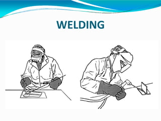
WELDING
⚫Welding is a materials joining process which
produces joint of materials by heating them to
suitable temperatures with orwithout theapplication
of pressure and with or without the use of filler
material.
⚫ Welding is used for making permanent joints.
⚫ It is used in the manufactureof automobile bodies, aircraft
frames, railway wagons, machine frames, structural works,
tanks, furniture, boilers, general repairwork and ship building.
TYPES
⚫PlasticWeldingor PressureWelding
The pieceof metal to be joined are heated toa
plastic state and forced together by external
pressure
(Ex) Resistance welding
⚫Fusion Welding or Non-PressureWelding
The material at the joint is heated toa moltenstateand allowed
tosolidify
(Ex) Gas welding, Arcwelding
Classification of welding processes:
(i). Arcwelding
⚫ Carbonarc
⚫ Metal arc
⚫ Metal inertgas
⚫ Tungsten inertgas
⚫ Plasmaarc
⚫ Submerged arc
⚫ Electro-slag
⚫Atomic Hydrogen
(ii). GasWelding
⚫ Oxy-acetylene
⚫ Air-acetylene
⚫ Oxy-hydrogen
(iii). ResistanceWelding
⚫ Butt
⚫ Spot
⚫ Seam
⚫ Projection
⚫ Percussion
(iv)Thermit Welding
(v)Solid State Welding
Friction
Ultrasonic
Diffusion
Explosive
Forge
(vi)Newer Welding
Electron-beam
Laser
(vii)Related Process
Oxy-acetylene cutting
Arc cutting
Hard facing
Brazing
Soldering
6
Terminologies associated with welding
process
⚫ Base metal – Work pieces to be joined
⚫ Weld bead – Material deposited by the
process of welding
⚫ Puddle – Portion of the base material which
is melted by the heat of welding.
⚫ Weld pass – Movement of welding torch
from oneend of the joint to theother.
⚫ Tack weld – Temporaryweld done at the
ends of thework pieces.
kss@2007
Types of Weld joints
EDGE PREPARATION IN WELDING
kss@2007 9
EDGE PREPARATION IN WELDING
(b) Single V
(d) Single U
(c) Double V
(a) Square faces
(e) Double U
⚫Toensurecompletepenetrationand sound weld ,
edgepreparation isessential.
70 to 90 degrees
Root
TYPE OF EDGES
GAS WELDING
⚫ Gas welding is called an oxy-fuel gas welding as heat is derives from
combustionof acetylenewith oxygen.
⚫ Fuel is generallyused is acetylene becauseof high temperature
generated during the process is i.e 31000c
GAS CHEMICAL
FORMULA
HEAT CONTENT FLAME
TEMPERATURE
Acetylene C2H2 55 31000c
Propylene C3H 88 25000c
Propane C3H8 93 24500c
Hydrogen H2 10 23900c
GAS WELDING PRINCIPLE
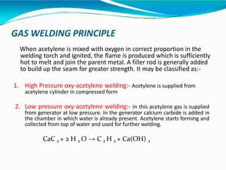
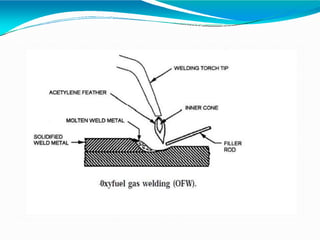
When acetylene is mixed with oxygen in correct proportion in the
welding torch and ignited, the flame is produced which is sufficiently
hot to melt and join the parent metal. A filler rod is generally added
to build up the seam for greater strength. It may be classified as:-
1. High Pressure oxy-acetylene welding:- Acetylene is supplied from
acetylene cylinder in compressed form
2. Low pressure oxy-acetylene welding:- In this acetylene gas is supplied
from generator at low pressure. In the generator calcium carbide is added in
the chamber in which water is already present. Acetylene starts forming and
collected from top of water and used for further welding.
CaC 2 + 2 H 2 O → C 2 H 2 + Ca(OH) 2
TYPES OF FLAMES
 Neutral flame
 Oxidizing flame
 Carburizing flame
Three basic types of oxyacetylene flames used in oxyfuel-gas welding and cutting
operations: (a) neutral flame; (b) oxidizing flame; (c) carburizing, or reducing flame.
Neutral flame
when oxygen to acetylene ration 1.1:1 is called Neutral flame (It has a
balance of fuel gas and oxygen) (32000c). Inner core light blue colour and
outer core dark blue colour.
Used for welding steels, aluminium, copper and cast iron
Three basic types of oxyacetylene flames used in oxyfuel-gas welding and
cutting operations:
(a) neutral flame; (b) oxidizing flame; (c) carburizing, or reducing flame.
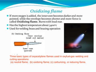
Oxidizing flame
⚫ If moreoxygen is added, the innercore becomes darkerand more
pointed, while the envelope becomes shorter and more fierce is
called Oxidizing flame. Burnswith loud roar.
⚫ Has the highest temperatureabout 34000c
⚫ Used forwelding brassand brazing operation
Three basic types of oxyacetylene flames used in oxyfuel-gas welding and
cutting operations:
(a) neutral flame; (b) oxidizing flame; (c) carburizing, or reducing flame.
Carburizing flame or Reducing Flame
If Oxygen supplied to the neutral flame is reduced, flame immediately
changes into a long white inner area (Feather) surrounded by a transparent
blue envelope is called Carburizing flame (30000c). Used for steel alloys
like for welding high carbon steel.
CHEMISTRY IN GAS WELDING
Stage 1
2C2H2 + 2O2 = 4CO + 2H2
Stage 2
4CO + 2H2 + 3O2 = 4CO2 + 2H2O
Stage 3
2C2H2 + 5 O2 = 4CO2 + 2H20 (vapour) + 1284.57 k J / mol
GAS WELDING TECHNIQUES
Leftward Welding Techniques Rightward Welding Techniques
GAS WELDING EQUIPMENT...
1. Oxygen Gas Cylinders- coloured Black or Blue
2. Acetylene Gas Cylinders- coloured Red
Pressure
Oxygen – 125 kg/cm2
Acetylene – 16 kg/cm2
3. Regulators
4. Pressure Gauges
5. Hoses
6. Welding torch
7. Check valve
8. Non returnvalve
9. Gas lighter
10. Protective clothing
Oxy-Acetylene welding
Pressure Regulator & Gauges
Gas Hoses
1. Nut coupler
2. Nipple
3. Hose coupler
4. Hose splicers
5. O clips
Welding Torch
Check Valve & Non return valve
The perpose of internal check valve is to reduce the possibility of
reverse flow gas.
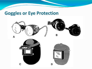
Goggles or Eye Protection
Protective Clothing & Gloves
Arc welding
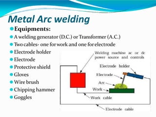
Metal Arc welding
⚫Equipments:
⚫A welding generator (D.C.) orTransformer (A.C.)
⚫Two cables- one forwork and one forelectrode
⚫Electrode holder
⚫Electrode
⚫Protective shield
⚫Gloves
⚫Wire brush
⚫Chipping hammer
⚫Goggles
Arc welding
Advantages
⚫ Mostefficientway to join
metals
⚫ Lowest-cost joining method
⚫ Joinsall commercial metals
⚫ Providesdesign f lexibility
Limitations
⚫ Manuallyapplied, therefore high
laborcost.
⚫ Need high energycausing
danger
⚫ Notconvenientfordisassembly.
⚫ Defects are hard todetectat
joints.
Comparison of A.C. and D.C. arc welding
Alternating Current (from Transformer)
 More efficiency
 Powerconsumption less
 Costof equipment is less
 Highervoltage – hence not safe
 Not suitable forwelding non ferrous metals
 Not preferred forwelding thin sections
 Any terminal can be connected to thework orelectrode
Comparison of A.C. and D.C. arc welding
Direct Current (from Generator)
 Less efficiency
 Powerconsumption more
 Costof equipment is more
 Low voltage – saferoperation
 suitable for both ferrous non ferrous metals
 preferred forwelding thin sections
 Positive terminal connected to thework
 Negative terminal connected to theelectrode
Polarities
Electrodes
 Filler rods are used in arc welding are called electrodes.
 Metallic wires having same composition as the metal to be weld.
Coated uniformly with a protective coating called flux. e.g
titanium oxide, potassium oxide, cellulose, iron or manganese,
Ferro silicates, carbonates, gums, clays, asbestos etc…
Types of Electrodes
Consumable
Non-consumable- D.C(Carbon, graphite) & A.C (Tungsten). Used
in carbon arc & TIG welding
Bare Electrode- Not coated with flux. Used in carbon arc & TIG
welding
Coated Electrodes(Stick Electrode)- coated with flux
Types of Fluxes
Gas forming- Isolating welding zone from ambient air. e.g
organic matter like wood pulp
Slag forming- china clay, felspar, manganese, & titanium
ores
Reducing- ferro silicon,ferro titanium,ferro manganese
reduces oxides
Stabilizing- Ionized the zone b/w electrode and part to be
weld and ensuring stable burning.
Binding- so that covering should have proper binding with
bare electrode.
FOREHAND WELDING & BACKHAND
WELDING
Torch tip
Direction of torch travel
Base metal
Bead
Base metal
Direction of torch travel
Bead
Torch tip
Base metal
Bead
A weld bead |
|
|
Forehand welding
less heat is flowing in the metal
used for relatively thin parts
|
|
|
Backhand welding
heat is concentrated into the metal
thicker parts are welded
kss@2007 37
kss@2007 38
Principle of Arc welding
Air
gap
(-) Charged
electrons
DC
Power
Supply
Cathode (-)
Anode (+)
(+) Charged
ions
•Arc is struck
•Electrons travel form cathode to
Anode at very high speed
•K.E of electrons converted to Heat
•Positively charged ions from
anode to Cathode provide protecting
shied
kss@2007 39
ARC WELDING PROCESS
Kalpakjian
Shielded Metal Arc Welding (SMAW): “Stick welding”
• Arc temperature is nearly 5500°C
• The electrode is also the filler rod
• Only for steel
• Strong welds if done properly (but often not)
•Very high heat input: good for thick parts, bad for grain growth and
distortion
Welding Tool Equipments
Gas Metal Arc Welding (GMAW): “MIG” (Metal-Inert-Gas)
• Complex mechanism but simple to perform and easy to automate
• The electrode is also the filler rod, fed continuously from a spool. It melts in the arc.
• For steel or aluminum
• Low skill level can achieve good weld
• Medium heat input: distortion and grain growth are significant
Kalpakjian
Gas Metal Arc Welding (GMAW): “MIG” (Metal-Inert-Gas)
Kalpakjian
www.difflock.com
www.scenta.co.uk
www.mig-welding.co.uk
Gas Metal Arc Welding (GMAW): “MIG” (Metal-Inert-Gas)
A fair/typical quality MIG weld (still hot!)
Gas Metal Arc Welding (GMAW): “MIG” (Metal-Inert-Gas)
Advantages of Metal Inert Gas Welding (MIG, GMAW):
•Continuous weld may be produced (no interruptions);
•High level of operators skill is not required;
•Slag removal is not required (no slag);
Disadvantages of Metal Inert Gas Welding (MIG, GMAW):
•Expensive and non-portable equipment is required;
•Outdoor application are limited because of effect of wind,
dispersing the shielding gas.
Kalpakjian
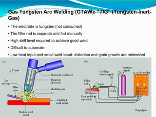
Gas Tungsten Arc Welding (GTAW): “TIG” (Tungsten-Inert-
Gas)
• The electrode is tungsten (not consumed)
• The filler rod is separate and fed manually
• High skill level required to achieve good weld
• Difficult to automate
• Low heat input and small weld bead: distortion and grain growth are minimized
Kalpakjian
Gas Tungsten Arc Welding (GTAW): “TIG” (Tungsten-Inert-
Gas)
www.kosman.net
www.steelmancycles.com
Gas Tungsten Arc Welding (GTAW): “TIG” (Tungsten-Inert-
Gas)
• Typical good quality TIG welds
•DCSP-mild steel, stainless steel
Copper & Titanium
•DCRP- Aluminium & Oxidised
aluminium casting
Gas Tungsten Arc Welding (GTAW): “TIG” (Tungsten-Inert-Gas)
ADVANTAGES:-
• Weld composition is close to that of the parent metal;
• High quality weld structure
• Slag removal is not required (no slag);
• Thermal distortions of work pieces are minimal due to
concentration of heat in small zone.
DIS-ADVANTAGES:-
• Low welding rate;
• Relatively expensive;
• Requres high level of operators skill.
CARBON ARC WELDING (CAW)
A process in which heat is generated by
an electric arc struck between an carbon
electrode and the work piece. The arc heats
and melts the work pieces edges, forming a
joint.
Carbon arc welding is the oldest welding
process.
If required, filler rod may be used in Carbon Arc
Welding. End of the rod is held in the arc zone.
The molten rod material is supplied to the weld
pool.
Shields (neutral gas, flux) may be used for weld
pool protection depending on type of welded
metal.
CARBON ARC WELDING (CAW)
ADVANTAGES:-
• Low cost of equipment and welding operation;
• High level of operator skill is not required;
• The process is easily automated;
• Low distortion of work piece.
DIS-ADVANTAGES:-
• Unstable quality of the weld (porosity);
• Carbon of electrode contaminates weld material with
carbides.
SUBMERGED ARC WELDING (CAW)
Submerged Arc Welding is a welding process, which utilizes a bare
consumable metallic electrode producing an arc between itself and the
work piece within a granular shielding flux applied around the weld.
Since the electrode is submerged into the flux, the arc is invisible. The flux
is partially melts and forms a slag protecting the weld pool from oxidation
and other atmospheric contaminations.
SUBMERGED ARC WELDING (CAW)
ADVANTAGES:-
•Very high welding rate;
•The process is suitable for automation;
•High quality weld structure
DIS-ADVANTAGES:-
•Weld may contain slag inclusions;
•Limited applications of the process - mostly for welding
horizontally located plates.
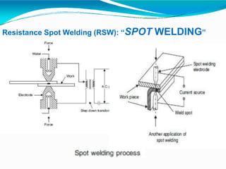
Resistance Spot Welding (RSW): “SPOT WELDING”
• No filler rod: electrical current is passed through metal under pressure
are minimized
• Distortion and grain growth
• Low skill level required
• Easy to automate
• Low heat input and no weld bead
Resistance Spot Welding (RSW): “SPOT WELDING”
ADVANTAGES:-
• Low Cost
• Less skilled worker required
• Higher productivity
• Can be easily automated
• No edge preperation required
APPLICATIONS:-
• Automobiles and aircraft industries
• Utensils and container
• Used for the welding of HSS, Low carbon steel,A,
CU, NI & NI alloys
Resistance SEAM Welding (RSW): “SEAM WELDING”
Seam welding is similar to spot welding except that the components to be joined
are gripped between revolving, circular copper rollers The
welding current is applied in a series of pulses resulting
in a corresponding series of overlapping spot welds being
made along the seam
Resistance SEAM Welding (RSW): “SEAM WELDING”
ADVANTAGES:-
• Produce gas or liquid tight joints.
• Several parallel seams can be produced.
• Overlap can be less than spot welding.
DIS-ADVANTAGES:-
• Cost of equipments is high.
• Welding can be done only along straight line.
• Difficult to weld thickness greater than 3mm.
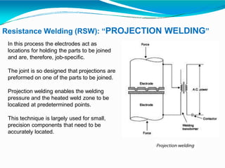
Resistance Welding (RSW): “PROJECTION WELDING”
In this process the electrodes act as
locations for holding the parts to be joined
and are, therefore, job-specific.
The joint is so designed that projections are
preformed on one of the parts to be joined.
Projection welding enables the welding
pressure and the heated weld zone to be
localized at predetermined points.
This technique is largely used for small,
precision components that need to be
accurately located.
Resistance Welding (RSW): “PROJECTION WELDING”
ADVANTAGES:-
• It is possible to weld more than one spot at a given time.
• Life of electrode is much longer than spot welding electrode.
• The uniformity and appearance of weld is better as compared to spot welding
DIS-ADVANTAGES:-
• Making of projections is an extra operation.
• All projection should be of same height.
• Metal which cannot support projection, cannot be weld.
APPLICATIONS:-
• Used for welding refrigerator condensor
Resistance Welding (RSW): “BUTT OR UPSET WELDING”
The two ends of the rods are brought
together with just sufficient force to
ensure the current can flow without
arcing.
The resistance of the joint interface
ensures that local heating will take
place on the passage of a heavy
electric current at low voltage.
When the metal in the joint zone has
reached its welding temperature, the
current is switched off and the axial
force on the joint is increased to
complete the weld.
Resistance Welding (RSW): “BUTT OR UPSET WELDING”
APPLICATIONS:-
• In wire drawing
Industries
• For producing butt
joint in tubes, pipes
& rods etc.
Resistance Welding (RSW): “FLASH BUTT WELDING”
Flash butt welding is similar to
upset butt welding except that
the heat required for melting is
obtained by means of an arc
rather than the simple resistance
welding.
Resistance Welding (RSW): “BUTT OR UPSET WELDING”
ADVANTAGES:-
• It consumes less welding
current
• Process is cheap.
• Process is fast.
• It offers 100% strength
factor.
• Preparation of weld
surface is not required.
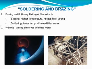
“SOLDERING AND BRAZING”
1. Brazing and Soldering: Melting of filler rod only
• Brazing: higher temperature, ~brass filler, strong
• Soldering: lower temp, ~tin-lead filler, weak
2. Welding: Melting of filler rod and base metal
Soldering
⚫ It is a low temperature joining process in
which fusible alloy or metal is introduced
in a liquid state between work piece to be
joined It is performed at temperatures
below 450ºC for joining. The filler metal is
called SOLDER
⚫ Soldering is used for,
⚫ Sealing, as in automotive radiators
or tin cans
⚫ Electrical Connections
⚫ Joining thermally sensitive
components
⚫ Joining dissimilar metals
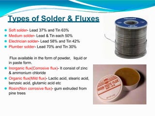
Types of Solder & Fluxes
⚫ Soft solder- Lead 37% and Tin 63%
⚫ Medium solder- Lead & Tin each 50%
⚫ Electrician solder- Lead 58% and Tin 42%
⚫ Plumber solder- Lead 70% and Tin 30%
Flux available in the form of powder, liquid or
in paste form.
⚫ Inorganic flux(Corrosive flux)- It consist of zinc
& ammonium chloride
⚫ Organic flux(Mild flux)- Lactic acid, stearic acid,
benzoic acid, glutamic acid etc
⚫ Rosin(Non corrosive flux)- gum extruded from
pine trees
Soldering Method
1. Soldering Iron Method 2. Torch Method
3. Spray Method 4. Induction Method
5. Dip & Wave Method 6. Resistance Method
7. Ultrasonic Method
APPLICATIONS:-
8. Condensation Method
⚫ Connection in radios & T.V sets etc
⚫ Radiator brass tubes for motor cars
⚫ Sometime used for repairing utensils
⚫ Wiring joint in electrical connections, battery and other
terminals
Brazing
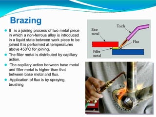
⚫ It is a joining process of two metal piece
in which a non-ferrous alloy is introduced
in a liquid state between work piece to be
joined It is performed at temperatures
above 450ºC for joining.
⚫ The filler metal is distributed by capillary
action.
⚫ The capillary action between base metal
and filler metal is higher than that
between base metal and flux.
⚫ Application of flux is by spraying,
brushing
Brazing
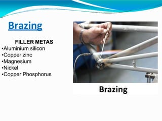
FILLER METAS
•Aluminium silicon
•Copper zinc
•Magnesium
•Nickel
•Copper Phosphorus
Brazing
APPLICATIONS:-
⚫Used for Fastening of pipes fittings, tanks, carbide tip on
tools, radiators, heat exchangers etc.
⚫It can join Cast metal to wrought metal and dissimilar
metals.
⚫Used for joining parts of cycle such as frame or rims
Brazing
ADVANTAGES:-
⚫ Dissimilar metals which can not be welded can be joined by brazing
⚫ Very thin metals can be joined
⚫ Metals with different thickness can be joined easily
⚫ In brazing thermal stresses are not produced in the work piece. Hence
there is no distortion
⚫ Using this process, carbides tips are brazed on the steel tool holders
DISADVANTAGES:-
⚫ Brazed joints have lesser strength compared to welding
⚫ Joint preparation cost is more
⚫ Can be used for thin sheet metal sections
“WELDING DEFECTS”
1. Lack of Penetration
It is the failure of the filler metal to penetrate
into the joint. It is due to
(a) Incorrect edge penetration
(b) Incorrect welding technique.
2. Lack of Fusion
Lack of fusion is the failure of the filler metal to
fuse with the parent metal. It is duo to
(a) Too fast travel
(b) Incorrect welding technique
(c) Insufficient heat
“WELDING DEFECTS”
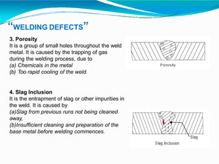
3. Porosity
It is a group of small holes throughout the weld
metal. It is caused by the trapping of gas
during the welding process, due to
(a) Chemicals in the metal
(b) Too rapid cooling of the weld.
4. Slag Inclusion
It is the entrapment of slag or other impurities in
the weld. It is caused by
(a)Slag from previous runs not being cleaned
away,
(b)Insufficient cleaning and preparation of the
base metal before welding commences.
“WELDING DEFECTS”
5. Undercuts
These are grooves or slots along the edges of
the weld caused by
(a) Too fast travel
(b) Bad welding technique
(c) Too much heat build-up.
6. Cracking
It is the formation of cracks either in the weld
metal or in the parent metal. It is due to
(a) Unsuitable parent metals used in the weld
(b) Bad welding technique
“WELDING DEFECTS”
7. Poor Weld Bead Appearance
If the width of weld bead deposited is not uniform or straight,
then the weld bead is termed as poor. It is due to (a) Improper
arc length,
(b) Improper welding technique,
(c ) Damaged electrode coating and poor electrode and
earthing connections.
It can be reduced by taking into
considerations the above factors.
8. Distortion
Distortion is due to high cooling rate, small diameter
electrode, poor clamping and slow arc
travel speed
“WELDING DEFECTS”
9. Overlays
These consist of metal that has flowed on to the parent metal without fusing with it.
The defect is due to
(a) Contamination of the surface of the parent metal
(b) Insufficient heat
10. Blowholes
These are large holes in the weld caused by
(a) Gas being trapped, due to moisture.
(b) Contamination of either the filler or parent metals.
11. Burn Through
It is the collapse of the weld pool due to
(a) Too much heat concentration
(b) Poor edge preparation.
12. Excessive Penetration
It is where the weld metal protrudes through the root of the weld. It is caused by
(a) Incorrect edge preparation
(b) Too much heat concentration
(c) Too slow travel.

More Related Content

Similar to FINAL WELDING UNIT 4 manufacturing process.pptx

Welding 2
Welding 2Welding 2
Welding 2
SourAbh GuleRia
 
welding system.............30.07.1997
welding system.............30.07.1997welding system.............30.07.1997
welding system.............30.07.1997
ashwinwarade30
 
Welding.ppt
Welding.pptWelding.ppt
Welding.ppt
AliVarmazyar1
 
Chapter 14 welding
Chapter 14 weldingChapter 14 welding
Chapter 14 welding
Valosha Valosha
 
Joining processes welding, soldering & Brazing
Joining processes  welding, soldering & BrazingJoining processes  welding, soldering & Brazing
Joining processes welding, soldering & Brazing
self employer
 
Manufacturing Technology I
Manufacturing Technology I Manufacturing Technology I
Manufacturing Technology I
Karthikeyan I
 
Advance Welding Process
Advance Welding ProcessAdvance Welding Process
Advance Welding Process
Sk Samsuddin
 
Gass welding
Gass weldingGass welding
Gass welding
Jaya Teja
 
welding
weldingwelding
weldingillpa
 
fdocuments.in_introduction-to-weldingppt-56c13478bad3b.ppt
fdocuments.in_introduction-to-weldingppt-56c13478bad3b.pptfdocuments.in_introduction-to-weldingppt-56c13478bad3b.ppt
fdocuments.in_introduction-to-weldingppt-56c13478bad3b.ppt
Praveen Kumar
 
Ch 19 gas welding, gas cutting & arc welding
Ch 19 gas welding, gas cutting & arc weldingCh 19 gas welding, gas cutting & arc welding
Ch 19 gas welding, gas cutting & arc welding
Nandan Choudhary
 
METAL JOINING PROCESS
METAL JOINING PROCESSMETAL JOINING PROCESS
METAL JOINING PROCESS
laxtwinsme
 
Welding Assignment
Welding AssignmentWelding Assignment
Welding Assignment
Dil Shah
 
Welding & joining
Welding & joiningWelding & joining
Welding & joining
Arup Nath
 
Welding+process
Welding+processWelding+process
Welding+process
Lakhwant Singh Khalsa
 
Unit 1 GAS AND ARC WELDING PROCESSES-Fundamental
Unit 1 GAS AND ARC WELDING PROCESSES-FundamentalUnit 1 GAS AND ARC WELDING PROCESSES-Fundamental
Unit 1 GAS AND ARC WELDING PROCESSES-Fundamental
LearnMech
 
Welding technology by A.Vinoth Jebaraj
Welding technology by A.Vinoth JebarajWelding technology by A.Vinoth Jebaraj
Welding technology by A.Vinoth Jebaraj
Vinoth Jebaraj A
 
Unit-V Joining Process-08 n.pptxjuahhajjjwjj
Unit-V Joining Process-08 n.pptxjuahhajjjwjjUnit-V Joining Process-08 n.pptxjuahhajjjwjj
Unit-V Joining Process-08 n.pptxjuahhajjjwjj
SakshiSalunkhe24
 

Similar to FINAL WELDING UNIT 4 manufacturing process.pptx (20)

Welding 2
Welding 2Welding 2
Welding 2
 
welding system.............30.07.1997
welding system.............30.07.1997welding system.............30.07.1997
welding system.............30.07.1997
 
1.1 welding
1.1 welding1.1 welding
1.1 welding
 
Welding.ppt
Welding.pptWelding.ppt
Welding.ppt
 
Chapter 14 welding
Chapter 14 weldingChapter 14 welding
Chapter 14 welding
 
Joining processes welding, soldering & Brazing
Joining processes  welding, soldering & BrazingJoining processes  welding, soldering & Brazing
Joining processes welding, soldering & Brazing
 
Manufacturing Technology I
Manufacturing Technology I Manufacturing Technology I
Manufacturing Technology I
 
Advance Welding Process
Advance Welding ProcessAdvance Welding Process
Advance Welding Process
 
Welding ppt
Welding pptWelding ppt
Welding ppt
 
Gass welding
Gass weldingGass welding
Gass welding
 
welding
weldingwelding
welding
 
fdocuments.in_introduction-to-weldingppt-56c13478bad3b.ppt
fdocuments.in_introduction-to-weldingppt-56c13478bad3b.pptfdocuments.in_introduction-to-weldingppt-56c13478bad3b.ppt
fdocuments.in_introduction-to-weldingppt-56c13478bad3b.ppt
 
Ch 19 gas welding, gas cutting & arc welding
Ch 19 gas welding, gas cutting & arc weldingCh 19 gas welding, gas cutting & arc welding
Ch 19 gas welding, gas cutting & arc welding
 
METAL JOINING PROCESS
METAL JOINING PROCESSMETAL JOINING PROCESS
METAL JOINING PROCESS
 
Welding Assignment
Welding AssignmentWelding Assignment
Welding Assignment
 
Welding & joining
Welding & joiningWelding & joining
Welding & joining
 
Welding+process
Welding+processWelding+process
Welding+process
 
Unit 1 GAS AND ARC WELDING PROCESSES-Fundamental
Unit 1 GAS AND ARC WELDING PROCESSES-FundamentalUnit 1 GAS AND ARC WELDING PROCESSES-Fundamental
Unit 1 GAS AND ARC WELDING PROCESSES-Fundamental
 
Welding technology by A.Vinoth Jebaraj
Welding technology by A.Vinoth JebarajWelding technology by A.Vinoth Jebaraj
Welding technology by A.Vinoth Jebaraj
 
Unit-V Joining Process-08 n.pptxjuahhajjjwjj
Unit-V Joining Process-08 n.pptxjuahhajjjwjjUnit-V Joining Process-08 n.pptxjuahhajjjwjj
Unit-V Joining Process-08 n.pptxjuahhajjjwjj
 

Recently uploaded

Nuclear Power Economics and Structuring 2024
Nuclear Power Economics and Structuring 2024Nuclear Power Economics and Structuring 2024
Nuclear Power Economics and Structuring 2024
Massimo Talia
 
Halogenation process of chemical process industries
Halogenation process of chemical process industriesHalogenation process of chemical process industries
Halogenation process of chemical process industries
MuhammadTufail242431
 
NO1 Uk best vashikaran specialist in delhi vashikaran baba near me online vas...
NO1 Uk best vashikaran specialist in delhi vashikaran baba near me online vas...NO1 Uk best vashikaran specialist in delhi vashikaran baba near me online vas...
NO1 Uk best vashikaran specialist in delhi vashikaran baba near me online vas...
Amil Baba Dawood bangali
 
Industrial Training at Shahjalal Fertilizer Company Limited (SFCL)
Industrial Training at Shahjalal Fertilizer Company Limited (SFCL)Industrial Training at Shahjalal Fertilizer Company Limited (SFCL)
Industrial Training at Shahjalal Fertilizer Company Limited (SFCL)
MdTanvirMahtab2
 
MCQ Soil mechanics questions (Soil shear strength).pdf
MCQ Soil mechanics questions (Soil shear strength).pdfMCQ Soil mechanics questions (Soil shear strength).pdf
MCQ Soil mechanics questions (Soil shear strength).pdf
Osamah Alsalih
 
Railway Signalling Principles Edition 3.pdf
Railway Signalling Principles Edition 3.pdfRailway Signalling Principles Edition 3.pdf
Railway Signalling Principles Edition 3.pdf
TeeVichai
 
weather web application report.pdf
weather web application report.pdfweather web application report.pdf
weather web application report.pdf
Pratik Pawar
 
ethical hacking-mobile hacking methods.ppt
ethical hacking-mobile hacking methods.pptethical hacking-mobile hacking methods.ppt
ethical hacking-mobile hacking methods.ppt
Jayaprasanna4
 
Gen AI Study Jams _ For the GDSC Leads in India.pdf
Gen AI Study Jams _ For the GDSC Leads in India.pdfGen AI Study Jams _ For the GDSC Leads in India.pdf
Gen AI Study Jams _ For the GDSC Leads in India.pdf
gdsczhcet
 
Cosmetic shop management system project report.pdf
Cosmetic shop management system project report.pdfCosmetic shop management system project report.pdf
Cosmetic shop management system project report.pdf
Kamal Acharya
 
Final project report on grocery store management system..pdf
Final project report on grocery store management system..pdfFinal project report on grocery store management system..pdf
Final project report on grocery store management system..pdf
Kamal Acharya
 
The role of big data in decision making.
The role of big data in decision making.The role of big data in decision making.
The role of big data in decision making.
ankuprajapati0525
 
Pile Foundation by Venkatesh Taduvai (Sub Geotechnical Engineering II)-conver...
Pile Foundation by Venkatesh Taduvai (Sub Geotechnical Engineering II)-conver...Pile Foundation by Venkatesh Taduvai (Sub Geotechnical Engineering II)-conver...
Pile Foundation by Venkatesh Taduvai (Sub Geotechnical Engineering II)-conver...
AJAYKUMARPUND1
 
Standard Reomte Control Interface - Neometrix
Standard Reomte Control Interface - NeometrixStandard Reomte Control Interface - Neometrix
Standard Reomte Control Interface - Neometrix
Neometrix_Engineering_Pvt_Ltd
 
Architectural Portfolio Sean Lockwood
Architectural Portfolio Sean LockwoodArchitectural Portfolio Sean Lockwood
Architectural Portfolio Sean Lockwood
seandesed
 
CME397 Surface Engineering- Professional Elective
CME397 Surface Engineering- Professional ElectiveCME397 Surface Engineering- Professional Elective
CME397 Surface Engineering- Professional Elective
karthi keyan
 
Democratizing Fuzzing at Scale by Abhishek Arya
Democratizing Fuzzing at Scale by Abhishek AryaDemocratizing Fuzzing at Scale by Abhishek Arya
Democratizing Fuzzing at Scale by Abhishek Arya
abh.arya
 
在线办理(ANU毕业证书)澳洲国立大学毕业证录取通知书一模一样
在线办理(ANU毕业证书)澳洲国立大学毕业证录取通知书一模一样在线办理(ANU毕业证书)澳洲国立大学毕业证录取通知书一模一样
在线办理(ANU毕业证书)澳洲国立大学毕业证录取通知书一模一样
obonagu
 
Vaccine management system project report documentation..pdf
Vaccine management system project report documentation..pdfVaccine management system project report documentation..pdf
Vaccine management system project report documentation..pdf
Kamal Acharya
 
LIGA(E)11111111111111111111111111111111111111111.ppt
LIGA(E)11111111111111111111111111111111111111111.pptLIGA(E)11111111111111111111111111111111111111111.ppt
LIGA(E)11111111111111111111111111111111111111111.ppt
ssuser9bd3ba
 

Recently uploaded (20)

Nuclear Power Economics and Structuring 2024
Nuclear Power Economics and Structuring 2024Nuclear Power Economics and Structuring 2024
Nuclear Power Economics and Structuring 2024
 
Halogenation process of chemical process industries
Halogenation process of chemical process industriesHalogenation process of chemical process industries
Halogenation process of chemical process industries
 
NO1 Uk best vashikaran specialist in delhi vashikaran baba near me online vas...
NO1 Uk best vashikaran specialist in delhi vashikaran baba near me online vas...NO1 Uk best vashikaran specialist in delhi vashikaran baba near me online vas...
NO1 Uk best vashikaran specialist in delhi vashikaran baba near me online vas...
 
Industrial Training at Shahjalal Fertilizer Company Limited (SFCL)
Industrial Training at Shahjalal Fertilizer Company Limited (SFCL)Industrial Training at Shahjalal Fertilizer Company Limited (SFCL)
Industrial Training at Shahjalal Fertilizer Company Limited (SFCL)
 
MCQ Soil mechanics questions (Soil shear strength).pdf
MCQ Soil mechanics questions (Soil shear strength).pdfMCQ Soil mechanics questions (Soil shear strength).pdf
MCQ Soil mechanics questions (Soil shear strength).pdf
 
Railway Signalling Principles Edition 3.pdf
Railway Signalling Principles Edition 3.pdfRailway Signalling Principles Edition 3.pdf
Railway Signalling Principles Edition 3.pdf
 
weather web application report.pdf
weather web application report.pdfweather web application report.pdf
weather web application report.pdf
 
ethical hacking-mobile hacking methods.ppt
ethical hacking-mobile hacking methods.pptethical hacking-mobile hacking methods.ppt
ethical hacking-mobile hacking methods.ppt
 
Gen AI Study Jams _ For the GDSC Leads in India.pdf
Gen AI Study Jams _ For the GDSC Leads in India.pdfGen AI Study Jams _ For the GDSC Leads in India.pdf
Gen AI Study Jams _ For the GDSC Leads in India.pdf
 
Cosmetic shop management system project report.pdf
Cosmetic shop management system project report.pdfCosmetic shop management system project report.pdf
Cosmetic shop management system project report.pdf
 
Final project report on grocery store management system..pdf
Final project report on grocery store management system..pdfFinal project report on grocery store management system..pdf
Final project report on grocery store management system..pdf
 
The role of big data in decision making.
The role of big data in decision making.The role of big data in decision making.
The role of big data in decision making.
 
Pile Foundation by Venkatesh Taduvai (Sub Geotechnical Engineering II)-conver...
Pile Foundation by Venkatesh Taduvai (Sub Geotechnical Engineering II)-conver...Pile Foundation by Venkatesh Taduvai (Sub Geotechnical Engineering II)-conver...
Pile Foundation by Venkatesh Taduvai (Sub Geotechnical Engineering II)-conver...
 
Standard Reomte Control Interface - Neometrix
Standard Reomte Control Interface - NeometrixStandard Reomte Control Interface - Neometrix
Standard Reomte Control Interface - Neometrix
 
Architectural Portfolio Sean Lockwood
Architectural Portfolio Sean LockwoodArchitectural Portfolio Sean Lockwood
Architectural Portfolio Sean Lockwood
 
CME397 Surface Engineering- Professional Elective
CME397 Surface Engineering- Professional ElectiveCME397 Surface Engineering- Professional Elective
CME397 Surface Engineering- Professional Elective
 
Democratizing Fuzzing at Scale by Abhishek Arya
Democratizing Fuzzing at Scale by Abhishek AryaDemocratizing Fuzzing at Scale by Abhishek Arya
Democratizing Fuzzing at Scale by Abhishek Arya
 
在线办理(ANU毕业证书)澳洲国立大学毕业证录取通知书一模一样
在线办理(ANU毕业证书)澳洲国立大学毕业证录取通知书一模一样在线办理(ANU毕业证书)澳洲国立大学毕业证录取通知书一模一样
在线办理(ANU毕业证书)澳洲国立大学毕业证录取通知书一模一样
 
Vaccine management system project report documentation..pdf
Vaccine management system project report documentation..pdfVaccine management system project report documentation..pdf
Vaccine management system project report documentation..pdf
 
LIGA(E)11111111111111111111111111111111111111111.ppt
LIGA(E)11111111111111111111111111111111111111111.pptLIGA(E)11111111111111111111111111111111111111111.ppt
LIGA(E)11111111111111111111111111111111111111111.ppt
 

FINAL WELDING UNIT 4 manufacturing process.pptx

  • 2. WELDING ⚫Welding is a materials joining process which produces joint of materials by heating them to suitable temperatures with orwithout theapplication of pressure and with or without the use of filler material. ⚫ Welding is used for making permanent joints. ⚫ It is used in the manufactureof automobile bodies, aircraft frames, railway wagons, machine frames, structural works, tanks, furniture, boilers, general repairwork and ship building.
  • 3. TYPES ⚫PlasticWeldingor PressureWelding The pieceof metal to be joined are heated toa plastic state and forced together by external pressure (Ex) Resistance welding ⚫Fusion Welding or Non-PressureWelding The material at the joint is heated toa moltenstateand allowed tosolidify (Ex) Gas welding, Arcwelding
  • 4.
  • 5. Classification of welding processes: (i). Arcwelding ⚫ Carbonarc ⚫ Metal arc ⚫ Metal inertgas ⚫ Tungsten inertgas ⚫ Plasmaarc ⚫ Submerged arc ⚫ Electro-slag ⚫Atomic Hydrogen (ii). GasWelding ⚫ Oxy-acetylene ⚫ Air-acetylene ⚫ Oxy-hydrogen (iii). ResistanceWelding ⚫ Butt ⚫ Spot ⚫ Seam ⚫ Projection ⚫ Percussion (iv)Thermit Welding (v)Solid State Welding Friction Ultrasonic Diffusion Explosive Forge (vi)Newer Welding Electron-beam Laser (vii)Related Process Oxy-acetylene cutting Arc cutting Hard facing Brazing Soldering
  • 6. 6 Terminologies associated with welding process ⚫ Base metal – Work pieces to be joined ⚫ Weld bead – Material deposited by the process of welding ⚫ Puddle – Portion of the base material which is melted by the heat of welding. ⚫ Weld pass – Movement of welding torch from oneend of the joint to theother. ⚫ Tack weld – Temporaryweld done at the ends of thework pieces. kss@2007
  • 7. Types of Weld joints
  • 9. kss@2007 9 EDGE PREPARATION IN WELDING (b) Single V (d) Single U (c) Double V (a) Square faces (e) Double U ⚫Toensurecompletepenetrationand sound weld , edgepreparation isessential. 70 to 90 degrees Root TYPE OF EDGES
  • 10. GAS WELDING ⚫ Gas welding is called an oxy-fuel gas welding as heat is derives from combustionof acetylenewith oxygen. ⚫ Fuel is generallyused is acetylene becauseof high temperature generated during the process is i.e 31000c GAS CHEMICAL FORMULA HEAT CONTENT FLAME TEMPERATURE Acetylene C2H2 55 31000c Propylene C3H 88 25000c Propane C3H8 93 24500c Hydrogen H2 10 23900c
  • 11. GAS WELDING PRINCIPLE When acetylene is mixed with oxygen in correct proportion in the welding torch and ignited, the flame is produced which is sufficiently hot to melt and join the parent metal. A filler rod is generally added to build up the seam for greater strength. It may be classified as:- 1. High Pressure oxy-acetylene welding:- Acetylene is supplied from acetylene cylinder in compressed form 2. Low pressure oxy-acetylene welding:- In this acetylene gas is supplied from generator at low pressure. In the generator calcium carbide is added in the chamber in which water is already present. Acetylene starts forming and collected from top of water and used for further welding. CaC 2 + 2 H 2 O → C 2 H 2 + Ca(OH) 2
  • 12.
  • 13. TYPES OF FLAMES  Neutral flame  Oxidizing flame  Carburizing flame
  • 14. Three basic types of oxyacetylene flames used in oxyfuel-gas welding and cutting operations: (a) neutral flame; (b) oxidizing flame; (c) carburizing, or reducing flame. Neutral flame when oxygen to acetylene ration 1.1:1 is called Neutral flame (It has a balance of fuel gas and oxygen) (32000c). Inner core light blue colour and outer core dark blue colour. Used for welding steels, aluminium, copper and cast iron
  • 15. Three basic types of oxyacetylene flames used in oxyfuel-gas welding and cutting operations: (a) neutral flame; (b) oxidizing flame; (c) carburizing, or reducing flame. Oxidizing flame ⚫ If moreoxygen is added, the innercore becomes darkerand more pointed, while the envelope becomes shorter and more fierce is called Oxidizing flame. Burnswith loud roar. ⚫ Has the highest temperatureabout 34000c ⚫ Used forwelding brassand brazing operation
  • 16. Three basic types of oxyacetylene flames used in oxyfuel-gas welding and cutting operations: (a) neutral flame; (b) oxidizing flame; (c) carburizing, or reducing flame. Carburizing flame or Reducing Flame If Oxygen supplied to the neutral flame is reduced, flame immediately changes into a long white inner area (Feather) surrounded by a transparent blue envelope is called Carburizing flame (30000c). Used for steel alloys like for welding high carbon steel.
  • 17. CHEMISTRY IN GAS WELDING Stage 1 2C2H2 + 2O2 = 4CO + 2H2 Stage 2 4CO + 2H2 + 3O2 = 4CO2 + 2H2O Stage 3 2C2H2 + 5 O2 = 4CO2 + 2H20 (vapour) + 1284.57 k J / mol
  • 18. GAS WELDING TECHNIQUES Leftward Welding Techniques Rightward Welding Techniques
  • 19. GAS WELDING EQUIPMENT... 1. Oxygen Gas Cylinders- coloured Black or Blue 2. Acetylene Gas Cylinders- coloured Red Pressure Oxygen – 125 kg/cm2 Acetylene – 16 kg/cm2 3. Regulators 4. Pressure Gauges 5. Hoses 6. Welding torch 7. Check valve 8. Non returnvalve 9. Gas lighter 10. Protective clothing
  • 23. Gas Hoses 1. Nut coupler 2. Nipple 3. Hose coupler 4. Hose splicers 5. O clips
  • 25. Check Valve & Non return valve The perpose of internal check valve is to reduce the possibility of reverse flow gas.
  • 26. Goggles or Eye Protection
  • 29. Metal Arc welding ⚫Equipments: ⚫A welding generator (D.C.) orTransformer (A.C.) ⚫Two cables- one forwork and one forelectrode ⚫Electrode holder ⚫Electrode ⚫Protective shield ⚫Gloves ⚫Wire brush ⚫Chipping hammer ⚫Goggles
  • 30. Arc welding Advantages ⚫ Mostefficientway to join metals ⚫ Lowest-cost joining method ⚫ Joinsall commercial metals ⚫ Providesdesign f lexibility Limitations ⚫ Manuallyapplied, therefore high laborcost. ⚫ Need high energycausing danger ⚫ Notconvenientfordisassembly. ⚫ Defects are hard todetectat joints.
  • 31. Comparison of A.C. and D.C. arc welding Alternating Current (from Transformer)  More efficiency  Powerconsumption less  Costof equipment is less  Highervoltage – hence not safe  Not suitable forwelding non ferrous metals  Not preferred forwelding thin sections  Any terminal can be connected to thework orelectrode
  • 32. Comparison of A.C. and D.C. arc welding Direct Current (from Generator)  Less efficiency  Powerconsumption more  Costof equipment is more  Low voltage – saferoperation  suitable for both ferrous non ferrous metals  preferred forwelding thin sections  Positive terminal connected to thework  Negative terminal connected to theelectrode
  • 34. Electrodes  Filler rods are used in arc welding are called electrodes.  Metallic wires having same composition as the metal to be weld. Coated uniformly with a protective coating called flux. e.g titanium oxide, potassium oxide, cellulose, iron or manganese, Ferro silicates, carbonates, gums, clays, asbestos etc…
  • 35. Types of Electrodes Consumable Non-consumable- D.C(Carbon, graphite) & A.C (Tungsten). Used in carbon arc & TIG welding Bare Electrode- Not coated with flux. Used in carbon arc & TIG welding Coated Electrodes(Stick Electrode)- coated with flux
  • 36. Types of Fluxes Gas forming- Isolating welding zone from ambient air. e.g organic matter like wood pulp Slag forming- china clay, felspar, manganese, & titanium ores Reducing- ferro silicon,ferro titanium,ferro manganese reduces oxides Stabilizing- Ionized the zone b/w electrode and part to be weld and ensuring stable burning. Binding- so that covering should have proper binding with bare electrode.
  • 37. FOREHAND WELDING & BACKHAND WELDING Torch tip Direction of torch travel Base metal Bead Base metal Direction of torch travel Bead Torch tip Base metal Bead A weld bead | | | Forehand welding less heat is flowing in the metal used for relatively thin parts | | | Backhand welding heat is concentrated into the metal thicker parts are welded kss@2007 37
  • 38. kss@2007 38 Principle of Arc welding Air gap (-) Charged electrons DC Power Supply Cathode (-) Anode (+) (+) Charged ions •Arc is struck •Electrons travel form cathode to Anode at very high speed •K.E of electrons converted to Heat •Positively charged ions from anode to Cathode provide protecting shied
  • 40. Kalpakjian Shielded Metal Arc Welding (SMAW): “Stick welding” • Arc temperature is nearly 5500°C • The electrode is also the filler rod • Only for steel • Strong welds if done properly (but often not) •Very high heat input: good for thick parts, bad for grain growth and distortion
  • 42. Gas Metal Arc Welding (GMAW): “MIG” (Metal-Inert-Gas) • Complex mechanism but simple to perform and easy to automate • The electrode is also the filler rod, fed continuously from a spool. It melts in the arc. • For steel or aluminum • Low skill level can achieve good weld • Medium heat input: distortion and grain growth are significant Kalpakjian
  • 43. Gas Metal Arc Welding (GMAW): “MIG” (Metal-Inert-Gas) Kalpakjian
  • 44. www.difflock.com www.scenta.co.uk www.mig-welding.co.uk Gas Metal Arc Welding (GMAW): “MIG” (Metal-Inert-Gas) A fair/typical quality MIG weld (still hot!)
  • 45. Gas Metal Arc Welding (GMAW): “MIG” (Metal-Inert-Gas) Advantages of Metal Inert Gas Welding (MIG, GMAW): •Continuous weld may be produced (no interruptions); •High level of operators skill is not required; •Slag removal is not required (no slag); Disadvantages of Metal Inert Gas Welding (MIG, GMAW): •Expensive and non-portable equipment is required; •Outdoor application are limited because of effect of wind, dispersing the shielding gas.
  • 46. Kalpakjian Gas Tungsten Arc Welding (GTAW): “TIG” (Tungsten-Inert- Gas) • The electrode is tungsten (not consumed) • The filler rod is separate and fed manually • High skill level required to achieve good weld • Difficult to automate • Low heat input and small weld bead: distortion and grain growth are minimized
  • 47. Kalpakjian Gas Tungsten Arc Welding (GTAW): “TIG” (Tungsten-Inert- Gas)
  • 48. www.kosman.net www.steelmancycles.com Gas Tungsten Arc Welding (GTAW): “TIG” (Tungsten-Inert- Gas) • Typical good quality TIG welds •DCSP-mild steel, stainless steel Copper & Titanium •DCRP- Aluminium & Oxidised aluminium casting
  • 49. Gas Tungsten Arc Welding (GTAW): “TIG” (Tungsten-Inert-Gas) ADVANTAGES:- • Weld composition is close to that of the parent metal; • High quality weld structure • Slag removal is not required (no slag); • Thermal distortions of work pieces are minimal due to concentration of heat in small zone. DIS-ADVANTAGES:- • Low welding rate; • Relatively expensive; • Requres high level of operators skill.
  • 50. CARBON ARC WELDING (CAW) A process in which heat is generated by an electric arc struck between an carbon electrode and the work piece. The arc heats and melts the work pieces edges, forming a joint. Carbon arc welding is the oldest welding process. If required, filler rod may be used in Carbon Arc Welding. End of the rod is held in the arc zone. The molten rod material is supplied to the weld pool. Shields (neutral gas, flux) may be used for weld pool protection depending on type of welded metal.
  • 51. CARBON ARC WELDING (CAW) ADVANTAGES:- • Low cost of equipment and welding operation; • High level of operator skill is not required; • The process is easily automated; • Low distortion of work piece. DIS-ADVANTAGES:- • Unstable quality of the weld (porosity); • Carbon of electrode contaminates weld material with carbides.
  • 52. SUBMERGED ARC WELDING (CAW) Submerged Arc Welding is a welding process, which utilizes a bare consumable metallic electrode producing an arc between itself and the work piece within a granular shielding flux applied around the weld. Since the electrode is submerged into the flux, the arc is invisible. The flux is partially melts and forms a slag protecting the weld pool from oxidation and other atmospheric contaminations.
  • 53. SUBMERGED ARC WELDING (CAW) ADVANTAGES:- •Very high welding rate; •The process is suitable for automation; •High quality weld structure DIS-ADVANTAGES:- •Weld may contain slag inclusions; •Limited applications of the process - mostly for welding horizontally located plates.
  • 54. Resistance Spot Welding (RSW): “SPOT WELDING” • No filler rod: electrical current is passed through metal under pressure are minimized • Distortion and grain growth • Low skill level required • Easy to automate • Low heat input and no weld bead
  • 55. Resistance Spot Welding (RSW): “SPOT WELDING”
  • 56. Resistance Spot Welding (RSW): “SPOT WELDING” ADVANTAGES:- • Low Cost • Less skilled worker required • Higher productivity • Can be easily automated • No edge preperation required APPLICATIONS:- • Automobiles and aircraft industries • Utensils and container • Used for the welding of HSS, Low carbon steel,A, CU, NI & NI alloys
  • 57. Resistance SEAM Welding (RSW): “SEAM WELDING” Seam welding is similar to spot welding except that the components to be joined are gripped between revolving, circular copper rollers The welding current is applied in a series of pulses resulting in a corresponding series of overlapping spot welds being made along the seam
  • 58. Resistance SEAM Welding (RSW): “SEAM WELDING”
  • 59. Resistance SEAM Welding (RSW): “SEAM WELDING” ADVANTAGES:- • Produce gas or liquid tight joints. • Several parallel seams can be produced. • Overlap can be less than spot welding. DIS-ADVANTAGES:- • Cost of equipments is high. • Welding can be done only along straight line. • Difficult to weld thickness greater than 3mm.
  • 60. Resistance Welding (RSW): “PROJECTION WELDING” In this process the electrodes act as locations for holding the parts to be joined and are, therefore, job-specific. The joint is so designed that projections are preformed on one of the parts to be joined. Projection welding enables the welding pressure and the heated weld zone to be localized at predetermined points. This technique is largely used for small, precision components that need to be accurately located.
  • 61. Resistance Welding (RSW): “PROJECTION WELDING” ADVANTAGES:- • It is possible to weld more than one spot at a given time. • Life of electrode is much longer than spot welding electrode. • The uniformity and appearance of weld is better as compared to spot welding DIS-ADVANTAGES:- • Making of projections is an extra operation. • All projection should be of same height. • Metal which cannot support projection, cannot be weld. APPLICATIONS:- • Used for welding refrigerator condensor
  • 62. Resistance Welding (RSW): “BUTT OR UPSET WELDING” The two ends of the rods are brought together with just sufficient force to ensure the current can flow without arcing. The resistance of the joint interface ensures that local heating will take place on the passage of a heavy electric current at low voltage. When the metal in the joint zone has reached its welding temperature, the current is switched off and the axial force on the joint is increased to complete the weld.
  • 63. Resistance Welding (RSW): “BUTT OR UPSET WELDING” APPLICATIONS:- • In wire drawing Industries • For producing butt joint in tubes, pipes & rods etc.
  • 64. Resistance Welding (RSW): “FLASH BUTT WELDING” Flash butt welding is similar to upset butt welding except that the heat required for melting is obtained by means of an arc rather than the simple resistance welding.
  • 65. Resistance Welding (RSW): “BUTT OR UPSET WELDING” ADVANTAGES:- • It consumes less welding current • Process is cheap. • Process is fast. • It offers 100% strength factor. • Preparation of weld surface is not required.
  • 66. “SOLDERING AND BRAZING” 1. Brazing and Soldering: Melting of filler rod only • Brazing: higher temperature, ~brass filler, strong • Soldering: lower temp, ~tin-lead filler, weak 2. Welding: Melting of filler rod and base metal
  • 67. Soldering ⚫ It is a low temperature joining process in which fusible alloy or metal is introduced in a liquid state between work piece to be joined It is performed at temperatures below 450ºC for joining. The filler metal is called SOLDER ⚫ Soldering is used for, ⚫ Sealing, as in automotive radiators or tin cans ⚫ Electrical Connections ⚫ Joining thermally sensitive components ⚫ Joining dissimilar metals
  • 68. Types of Solder & Fluxes ⚫ Soft solder- Lead 37% and Tin 63% ⚫ Medium solder- Lead & Tin each 50% ⚫ Electrician solder- Lead 58% and Tin 42% ⚫ Plumber solder- Lead 70% and Tin 30% Flux available in the form of powder, liquid or in paste form. ⚫ Inorganic flux(Corrosive flux)- It consist of zinc & ammonium chloride ⚫ Organic flux(Mild flux)- Lactic acid, stearic acid, benzoic acid, glutamic acid etc ⚫ Rosin(Non corrosive flux)- gum extruded from pine trees
  • 69. Soldering Method 1. Soldering Iron Method 2. Torch Method 3. Spray Method 4. Induction Method 5. Dip & Wave Method 6. Resistance Method 7. Ultrasonic Method APPLICATIONS:- 8. Condensation Method ⚫ Connection in radios & T.V sets etc ⚫ Radiator brass tubes for motor cars ⚫ Sometime used for repairing utensils ⚫ Wiring joint in electrical connections, battery and other terminals
  • 70. Brazing ⚫ It is a joining process of two metal piece in which a non-ferrous alloy is introduced in a liquid state between work piece to be joined It is performed at temperatures above 450ºC for joining. ⚫ The filler metal is distributed by capillary action. ⚫ The capillary action between base metal and filler metal is higher than that between base metal and flux. ⚫ Application of flux is by spraying, brushing
  • 71. Brazing FILLER METAS •Aluminium silicon •Copper zinc •Magnesium •Nickel •Copper Phosphorus
  • 72. Brazing APPLICATIONS:- ⚫Used for Fastening of pipes fittings, tanks, carbide tip on tools, radiators, heat exchangers etc. ⚫It can join Cast metal to wrought metal and dissimilar metals. ⚫Used for joining parts of cycle such as frame or rims
  • 73. Brazing ADVANTAGES:- ⚫ Dissimilar metals which can not be welded can be joined by brazing ⚫ Very thin metals can be joined ⚫ Metals with different thickness can be joined easily ⚫ In brazing thermal stresses are not produced in the work piece. Hence there is no distortion ⚫ Using this process, carbides tips are brazed on the steel tool holders DISADVANTAGES:- ⚫ Brazed joints have lesser strength compared to welding ⚫ Joint preparation cost is more ⚫ Can be used for thin sheet metal sections
  • 74. “WELDING DEFECTS” 1. Lack of Penetration It is the failure of the filler metal to penetrate into the joint. It is due to (a) Incorrect edge penetration (b) Incorrect welding technique. 2. Lack of Fusion Lack of fusion is the failure of the filler metal to fuse with the parent metal. It is duo to (a) Too fast travel (b) Incorrect welding technique (c) Insufficient heat
  • 75. “WELDING DEFECTS” 3. Porosity It is a group of small holes throughout the weld metal. It is caused by the trapping of gas during the welding process, due to (a) Chemicals in the metal (b) Too rapid cooling of the weld. 4. Slag Inclusion It is the entrapment of slag or other impurities in the weld. It is caused by (a)Slag from previous runs not being cleaned away, (b)Insufficient cleaning and preparation of the base metal before welding commences.
  • 76. “WELDING DEFECTS” 5. Undercuts These are grooves or slots along the edges of the weld caused by (a) Too fast travel (b) Bad welding technique (c) Too much heat build-up. 6. Cracking It is the formation of cracks either in the weld metal or in the parent metal. It is due to (a) Unsuitable parent metals used in the weld (b) Bad welding technique
  • 77. “WELDING DEFECTS” 7. Poor Weld Bead Appearance If the width of weld bead deposited is not uniform or straight, then the weld bead is termed as poor. It is due to (a) Improper arc length, (b) Improper welding technique, (c ) Damaged electrode coating and poor electrode and earthing connections. It can be reduced by taking into considerations the above factors. 8. Distortion Distortion is due to high cooling rate, small diameter electrode, poor clamping and slow arc travel speed
  • 78. “WELDING DEFECTS” 9. Overlays These consist of metal that has flowed on to the parent metal without fusing with it. The defect is due to (a) Contamination of the surface of the parent metal (b) Insufficient heat 10. Blowholes These are large holes in the weld caused by (a) Gas being trapped, due to moisture. (b) Contamination of either the filler or parent metals. 11. Burn Through It is the collapse of the weld pool due to (a) Too much heat concentration (b) Poor edge preparation. 12. Excessive Penetration It is where the weld metal protrudes through the root of the weld. It is caused by (a) Incorrect edge preparation (b) Too much heat concentration (c) Too slow travel.