Downloaded 30 times


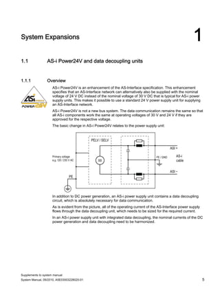
![Slaves
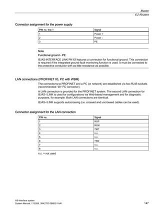
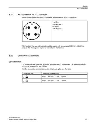
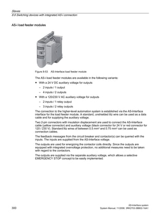
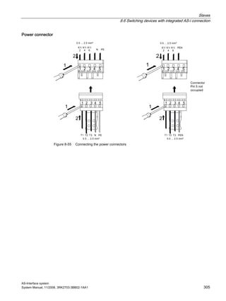
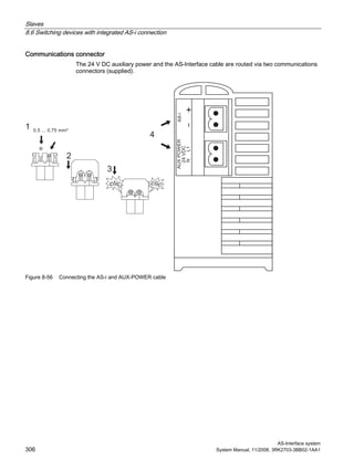
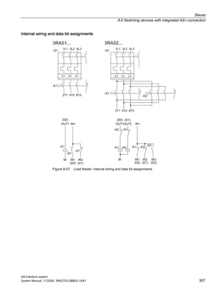
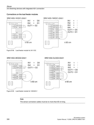
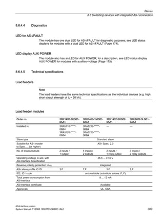
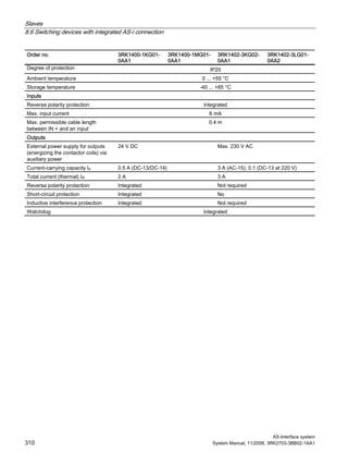
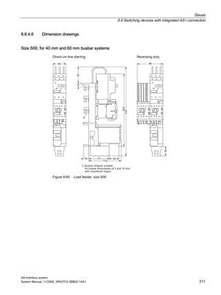
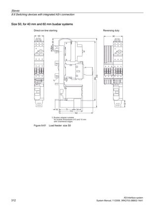
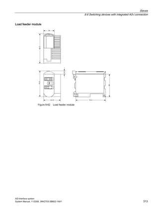
8.6 Switching devices with integrated AS-i connection
AS-Interface system
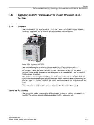
292 System Manual, 11/2008, 3RK2703-3BB02-1AA1
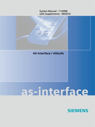
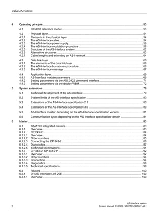
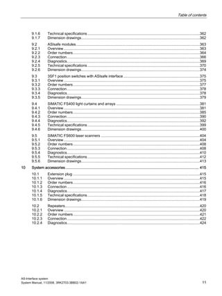
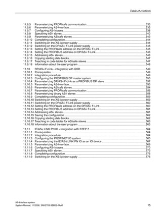
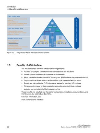
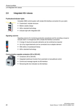
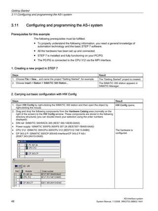
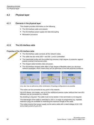
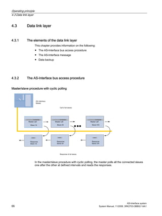
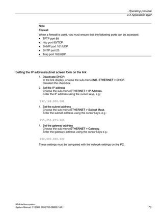
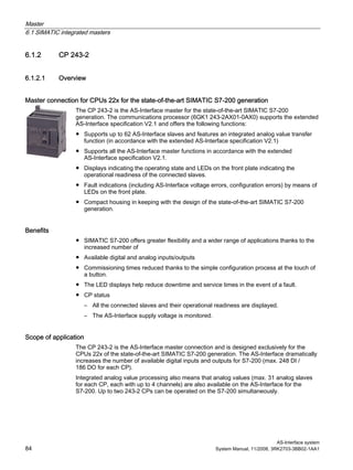
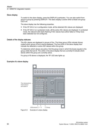
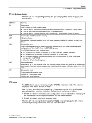
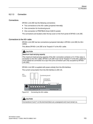
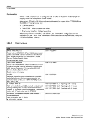
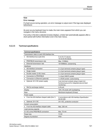
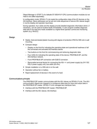
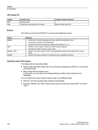
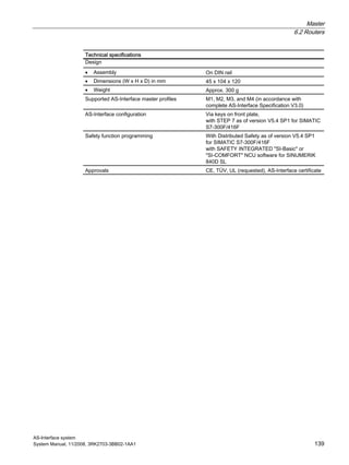
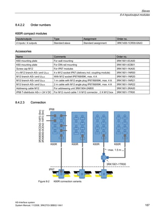
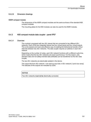
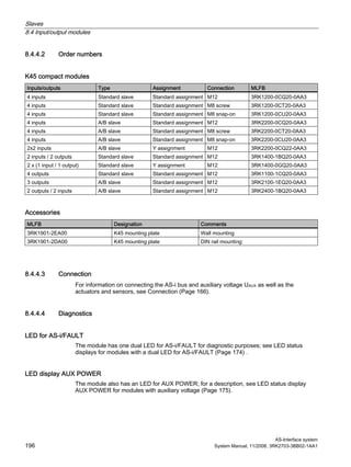
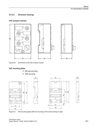
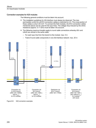
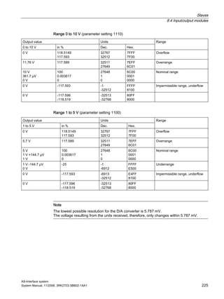
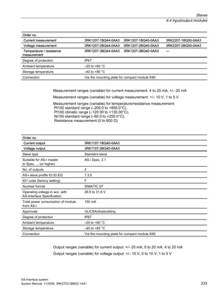
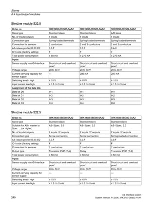
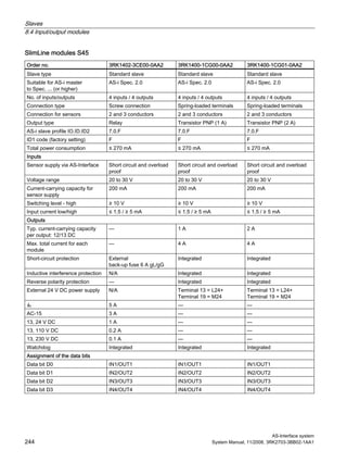
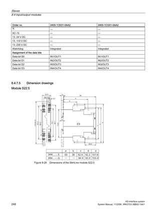
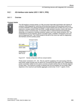
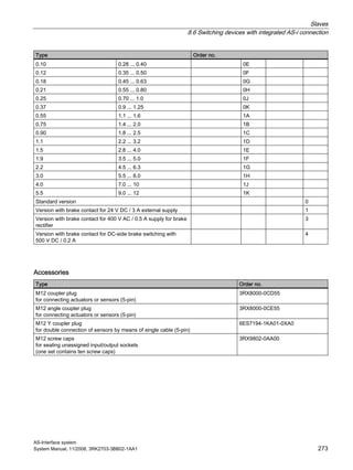
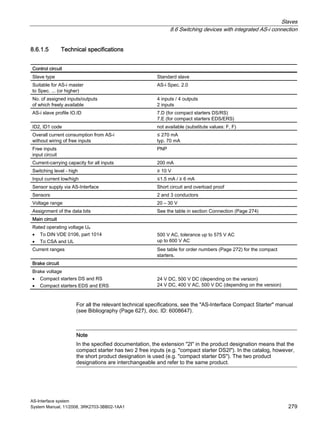
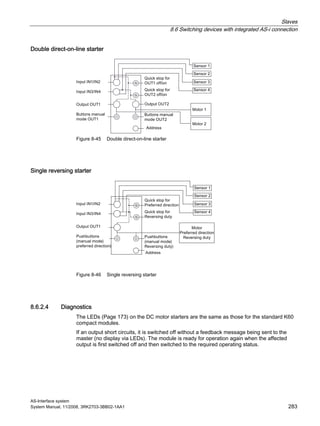
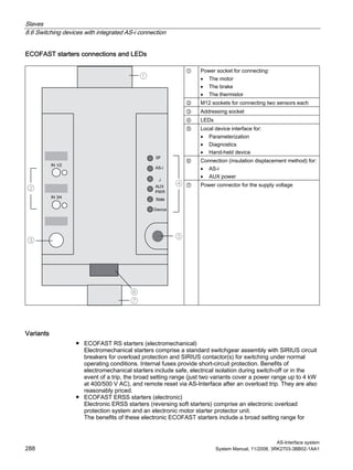
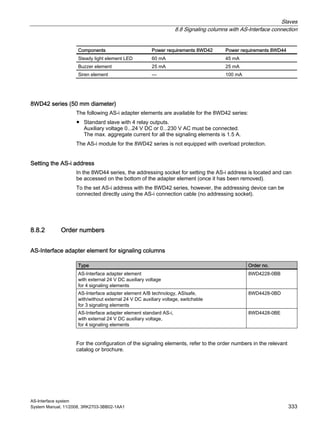
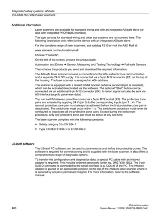
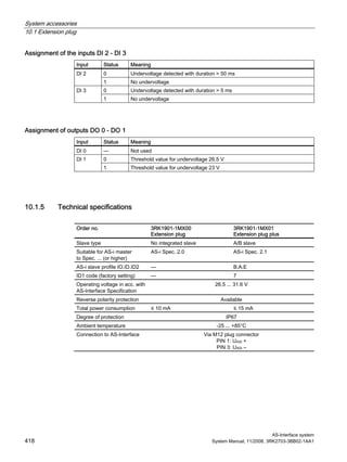
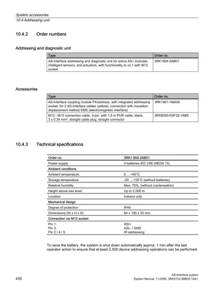
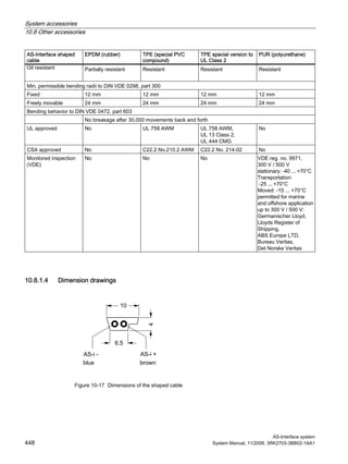
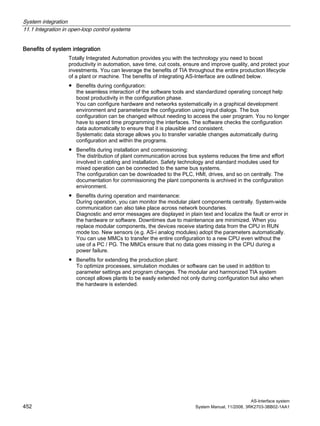
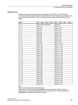
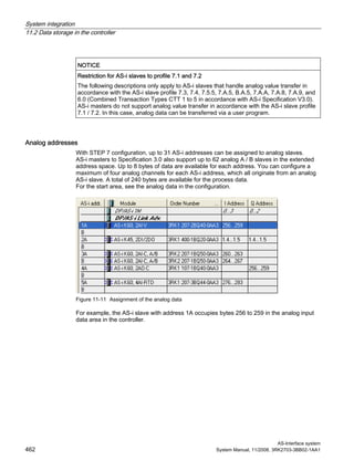
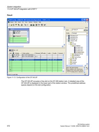
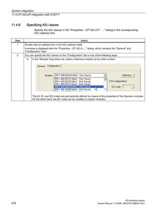
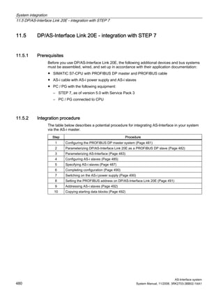
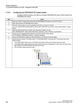
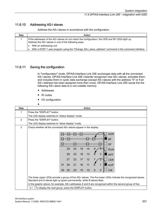
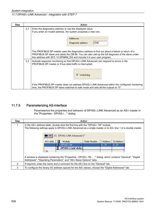
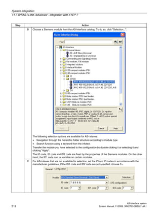
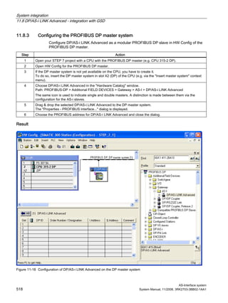
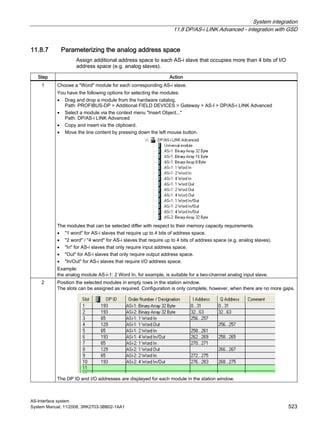
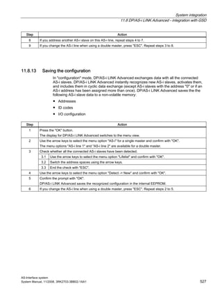
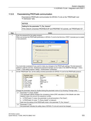
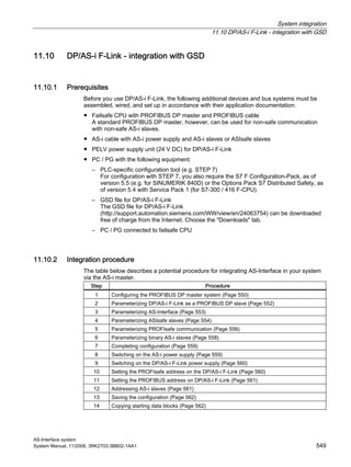
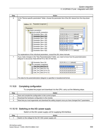
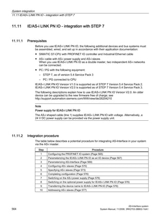
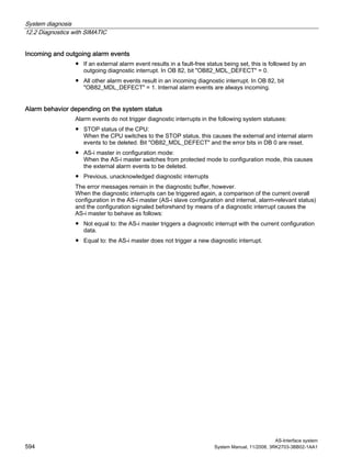
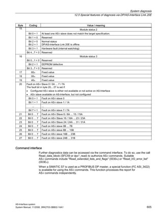
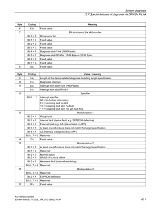
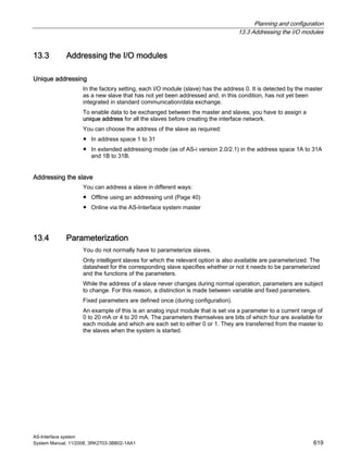
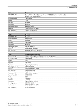
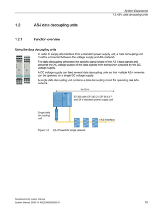
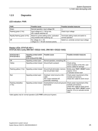
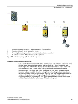
Assignment of outputs DO 0 - DO 3
Output Process image Status Signal
0 OFFDO 0 Motor CW
1 ON
0 OFFDO 1 Motor CCW
1 ON
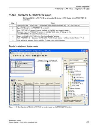
0 OFFDO 2 Brake
1 ON
0 ➜ 1 ACTIVE (trip reset)
0 OFF (creep feed)
DO 3 Trip reset / creep feed 1)
1 ON (creep feed)
1) Double assignment DO.3 with trip reset and creep feed.
Trip reset: Edge controlled with rising edge from [0] ➜ [1]
Creep feed: Level controlled [0] and [1] when D 0.0 or D 0.1 are triggered at the same time.
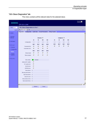
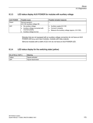
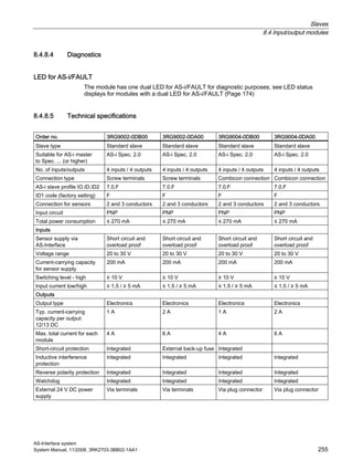
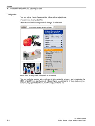
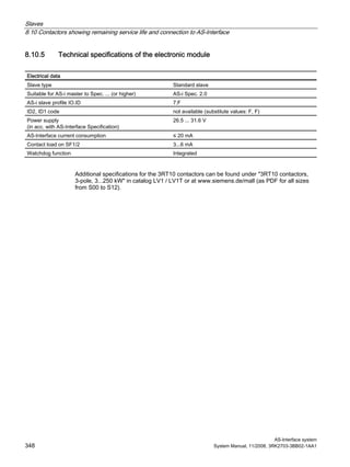
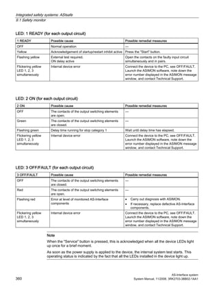
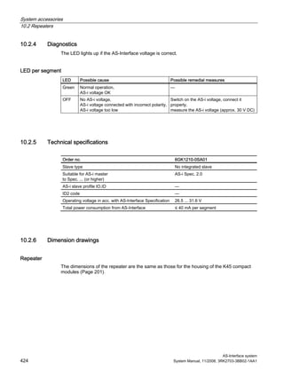
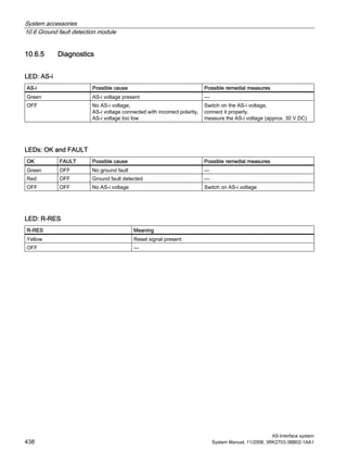
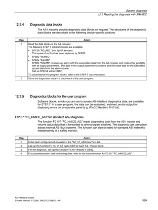
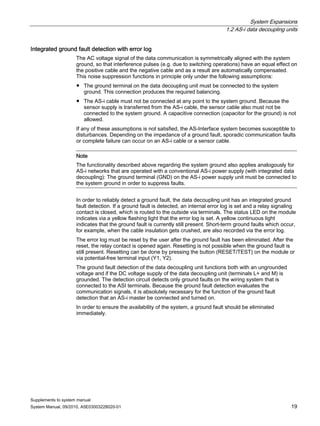
8.6.3.4 Diagnostics
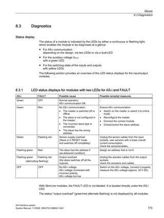
The ECOFAST starters are equipped with LEDs to indicate error statuses,
which enables comprehensive diagnostic activities to be carried out directly on the device.
AS-i Possible cause Possible remedial measures
Green Normal operation,
AS-i communication OK
—
Red No AS-i communication:
• The master is switched off or offline.
• The slave is not configured in the master.
• The incorrect slave type is connected.
• The slave has the wrong address.
Ensure AS-i communication:
• Switch on the master or switch it to online mode.
• Reconfigure the master.
• Connect the correct module.
• Check/correct the slave address.
Yellow/red flashing The AS-i slave has the address 0
(on delivery)
Assign an address that is not 0.
OFF No AS-i voltage,
AS-i voltage connected with incorrect polarity,
AS-i voltage too low
Switch on the AS-i voltage, connect it properly,
measure the AS-i voltage (approx. 30 V DC)](https://image.slidesharecdn.com/uabv6w96sd2atwahrqps-signature-8cf552cbae5741209e73d76315d6227712e4af3c534b4de5ef70d54611ba47f4-poli-150402172610-conversion-gate01/85/As-interface-system-manual-2008-11_x-2010-09_en-us-292-320.jpg)


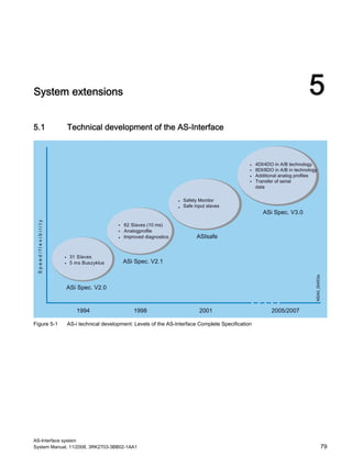
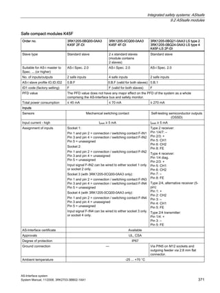
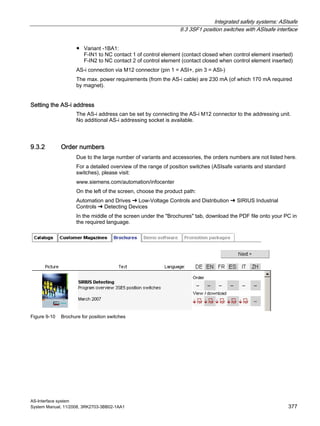
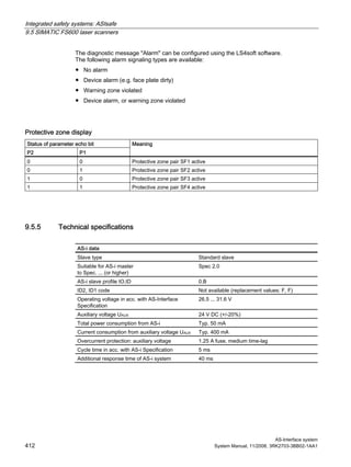
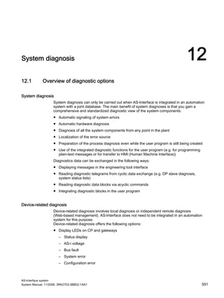
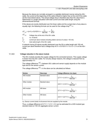
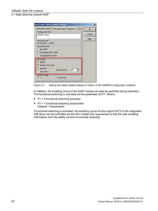
![Integrated safety systems: ASIsafe
9.1 Safety monitor
AS-Interface system
System Manual, 11/2008, 3RK2703-3BB02-1AA1 353
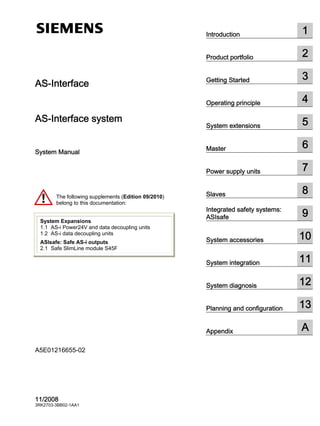
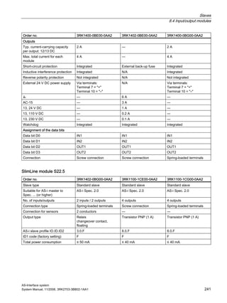
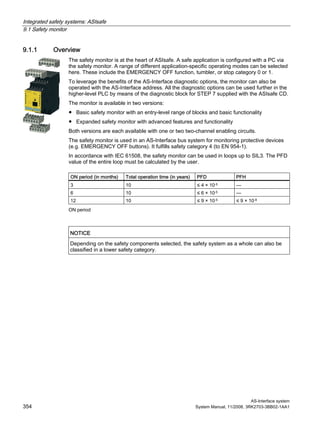
9.1 Safety monitor
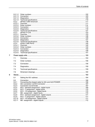
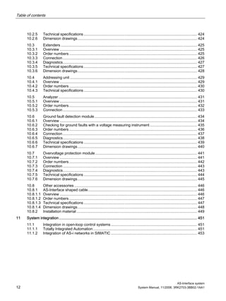
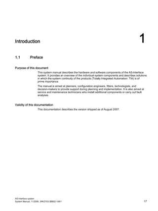
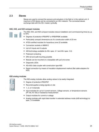
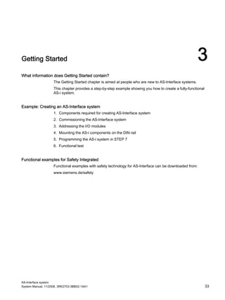
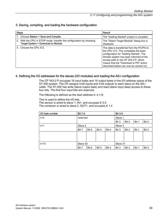
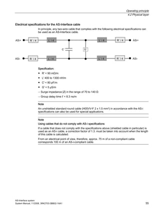
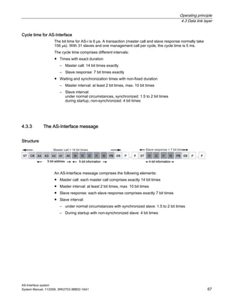
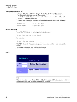
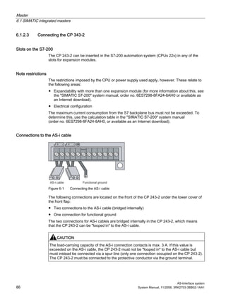
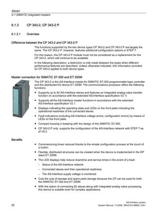
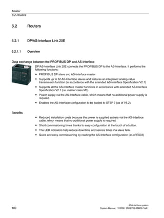
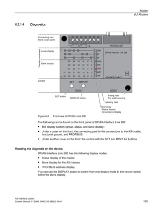
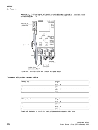
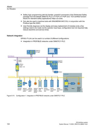
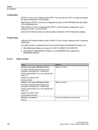
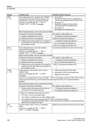
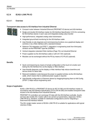
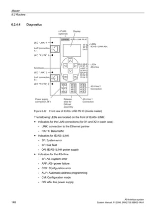
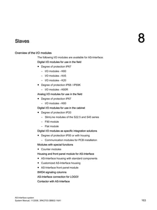
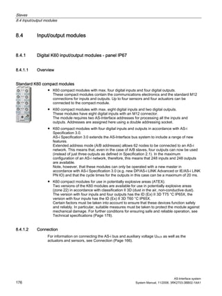
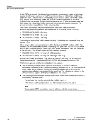
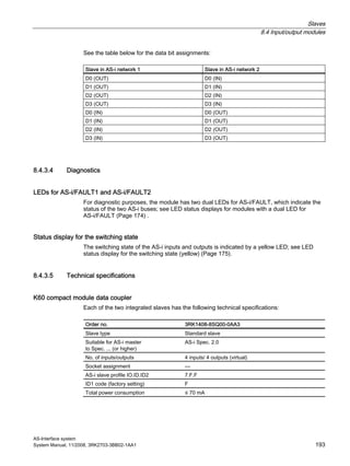
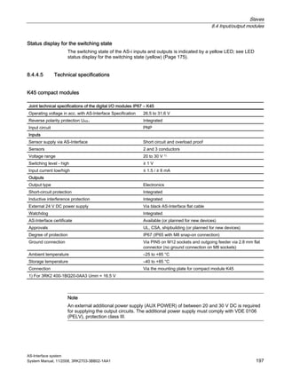
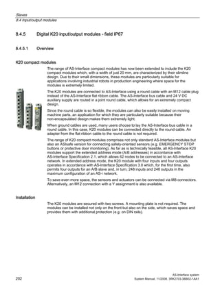
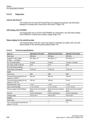
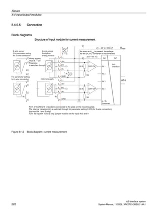
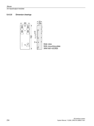
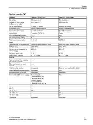
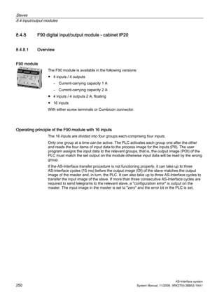
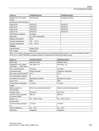
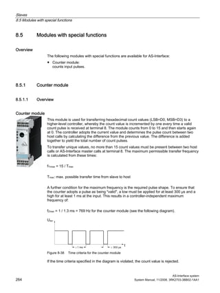
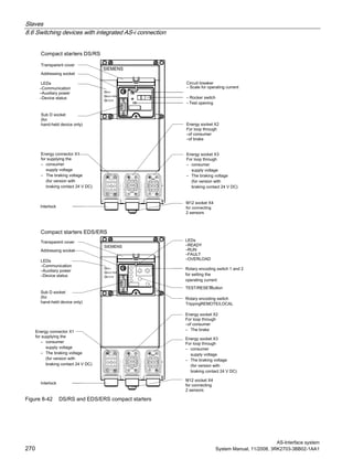
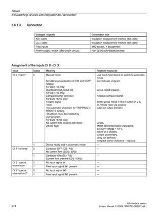
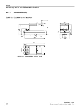
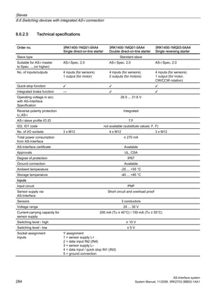
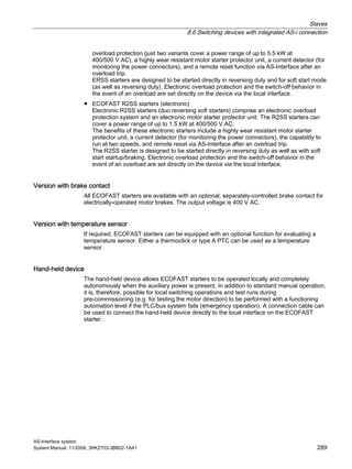
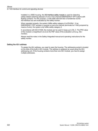
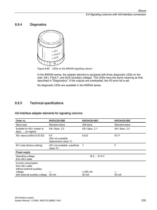
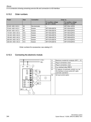
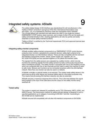
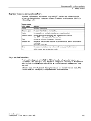
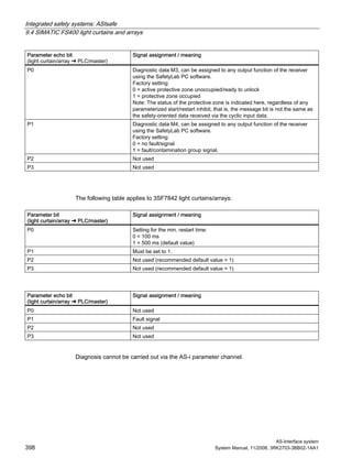
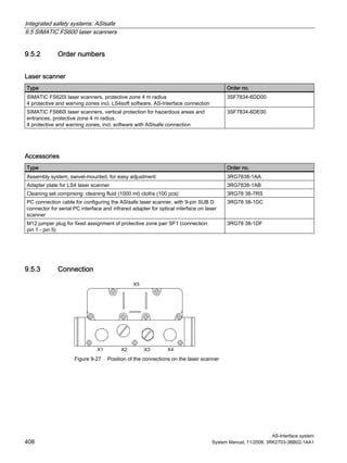
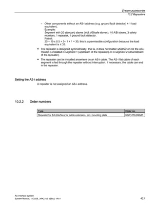
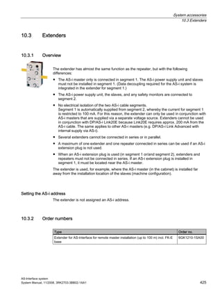
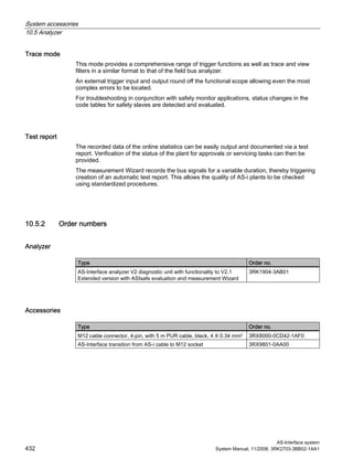
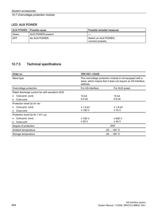
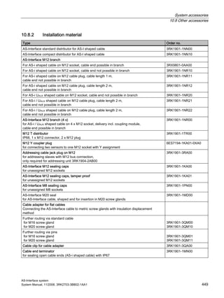
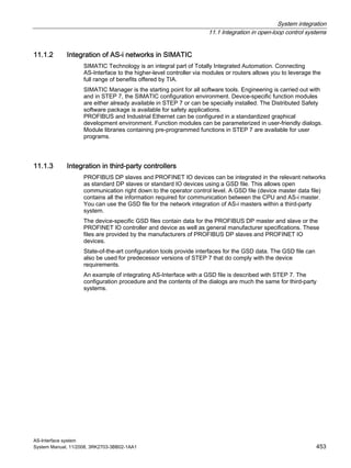
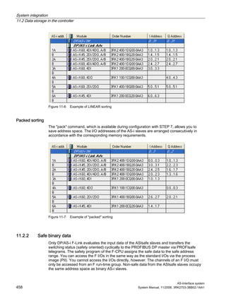
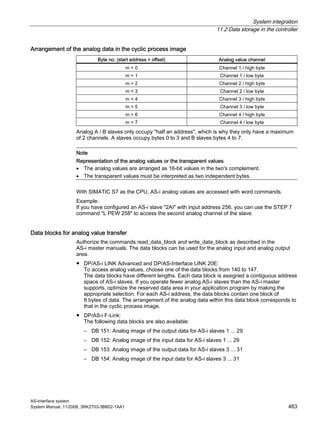
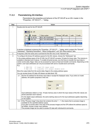
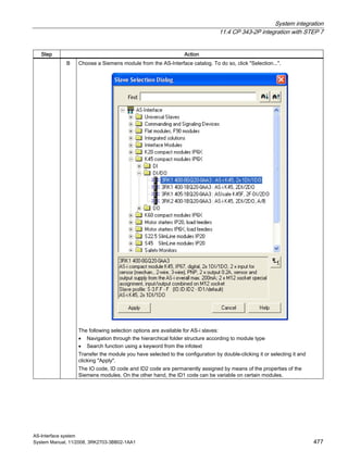
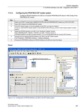
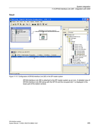
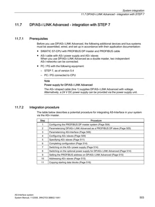
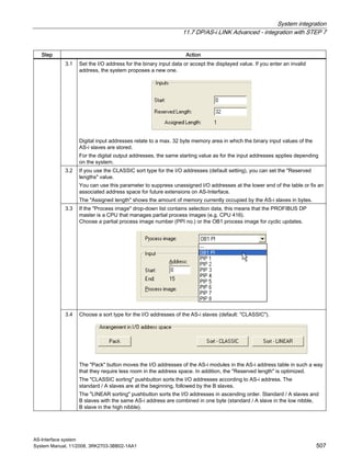
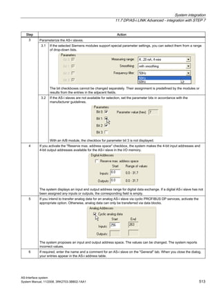
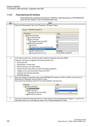
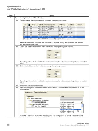
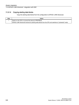
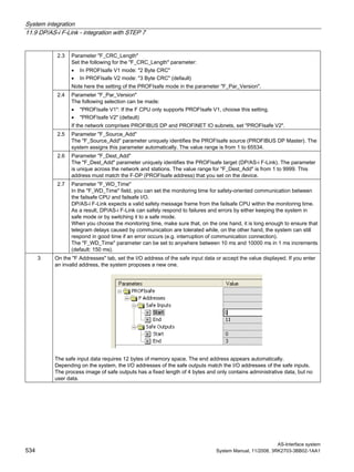
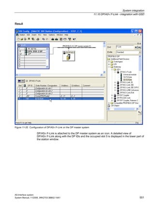
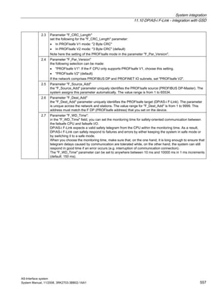
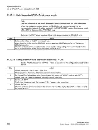
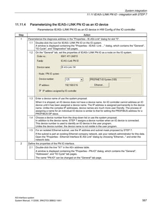
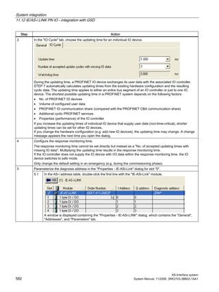
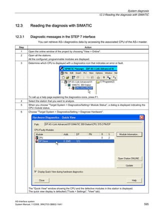
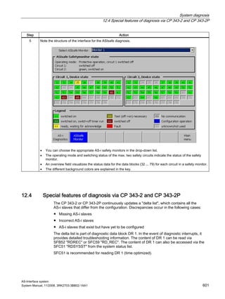
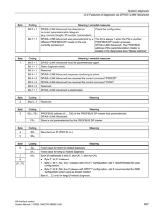
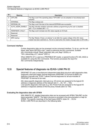
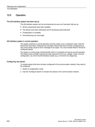
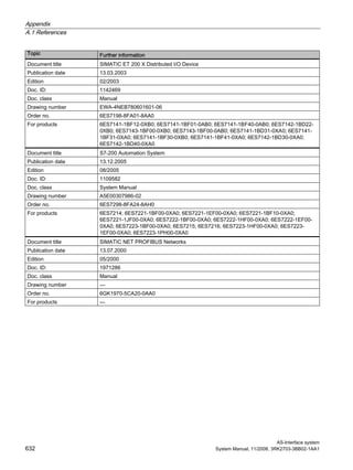
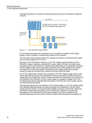
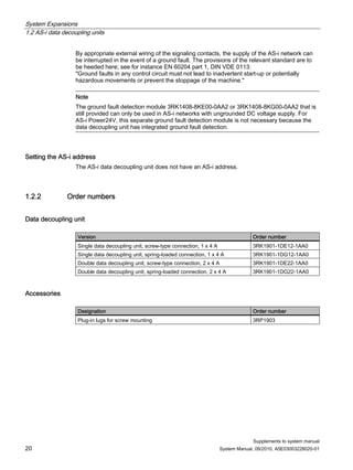
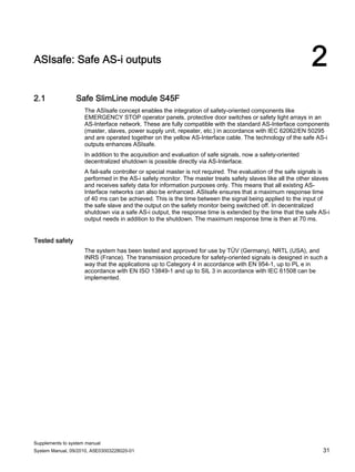
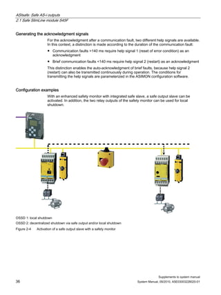
Functional principle
The safety monitor monitors data communication on the AS-Interface cable. For safe slaves,
dynamic code sequences (8x4 bit data sequence), which are stored in every slave, are
transferred.
These are "learnt" by the safety monitor during commissioning. During operation, the safety
monitor compares in each cycle the target and actual sequence and, if any discrepancies are
identified (e.g. due to device failure, communication faults, etc.), initiates a safe shutdown
within 40 ms. The restart time is 100 ms. A range of safe field and cabinet modules as well
as intelligent safety sensors and control devices with an AS-Interface chip are available as
slaves.
Bus communication and the data protocol have been deemed safe by the BIA and the
technology has been certified by TÜV.
The system can be used up to category 4 to EN 954-1 or up to SIL 3 to IEC 61508 [10] and
can be used for stop category 0 and 1 to EN 60204-1.
Master query
Standard PLC and
standard master
Safe slave
AS-i
power
supply
unit
Safety monitor
Slave reply
0 1 0 1
0 1 1 0
0 1 1 1
1 0 0 1
1 0 1 0
1 0 1 1
1 1 0 1
1 1 1 0
0 1 0 1
0 1 1 0
0 1 1 1
1 0 0 1
1 0 1 0
1 0 1 1
1 1 0 1
1 1 1 0
Comparator
SETPOINT
table
ACTUAL
table
Analog
interface
Opto-
coupler
Pre-
processing
D0
D1
D2
D3
0 1 0 1
0 1 1 0
0 1 1 1
1 0 0 1
1 0 1 0
1 0 1 1
1 1 0 1
1 1 1 0
“ON”
0 0 0 0
Sensors
Channel 1
sequence
generator
Channel 2
sequence
generator
D3 D2 D1 D0
Channel 1 Channel 2
Pulse
Standard AS-i
slave connection
Occupied
Figure 9-1 ASIsafe functional principle](https://image.slidesharecdn.com/uabv6w96sd2atwahrqps-signature-8cf552cbae5741209e73d76315d6227712e4af3c534b4de5ef70d54611ba47f4-poli-150402172610-conversion-gate01/85/As-interface-system-manual-2008-11_x-2010-09_en-us-353-320.jpg)


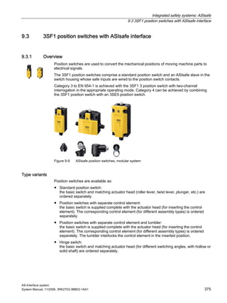

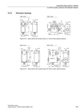


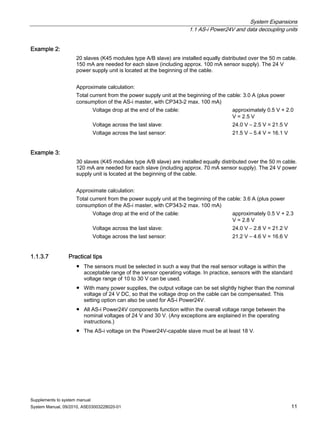
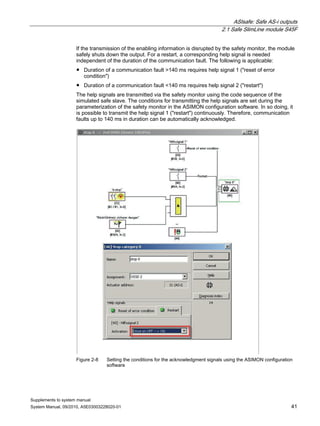
![System integration
11.11 IE/AS-i LINK PN IO - integration with STEP 7
AS-Interface system
System Manual, 11/2008, 3RK2703-3BB02-1AA1 569
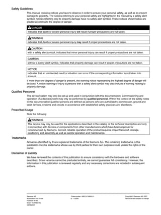
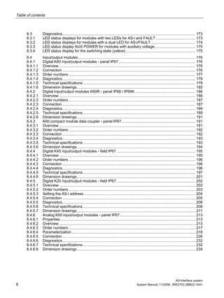
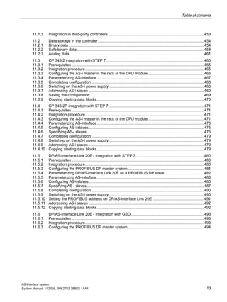
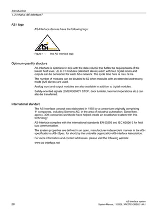
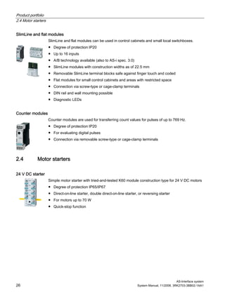
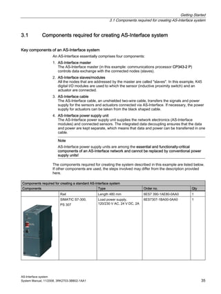
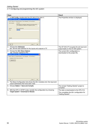
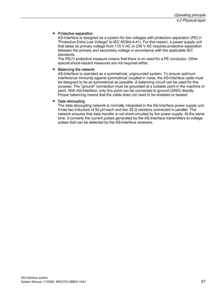
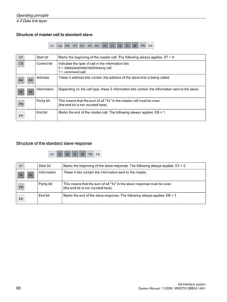
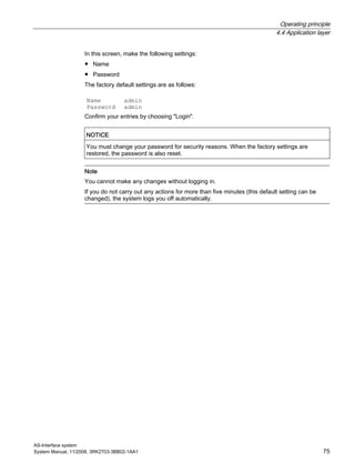
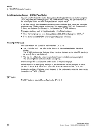
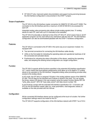
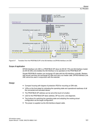
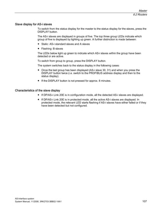
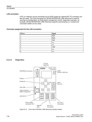
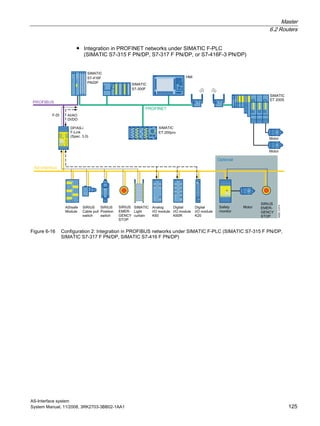
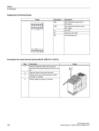
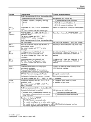
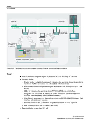
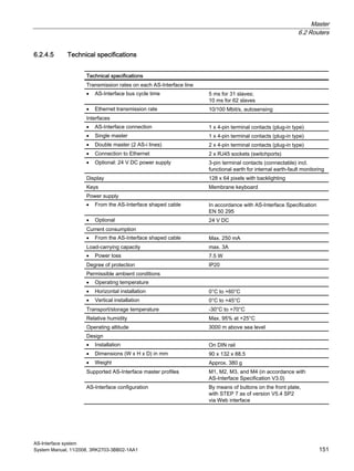
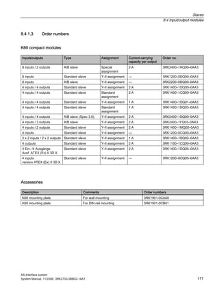
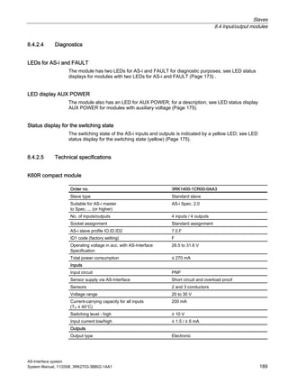
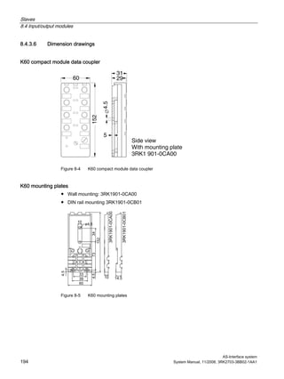
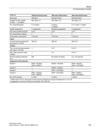
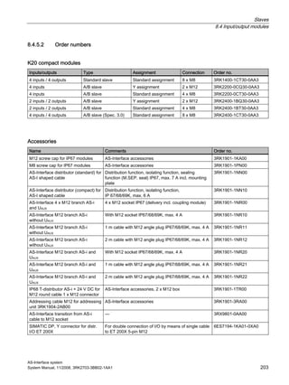
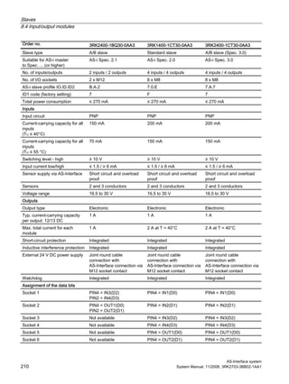
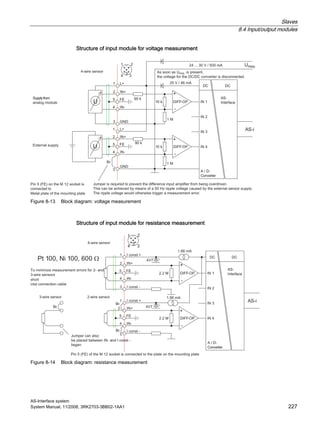
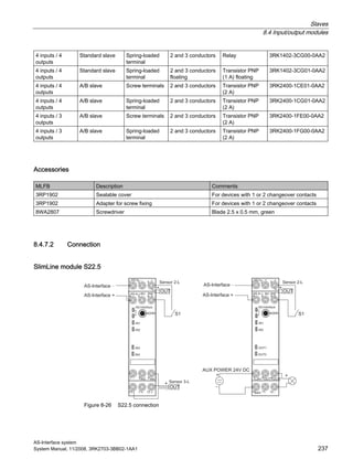
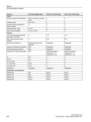
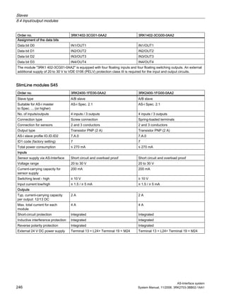
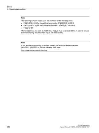
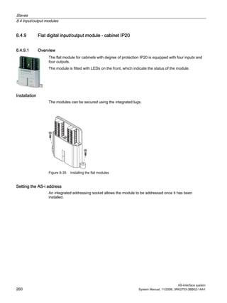
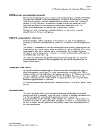
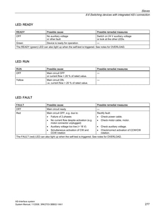
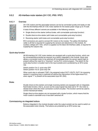
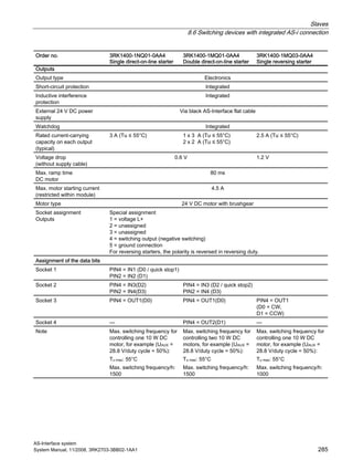
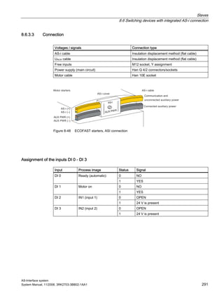
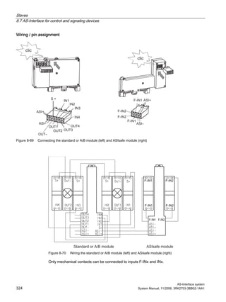
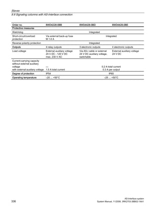
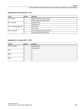
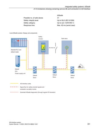
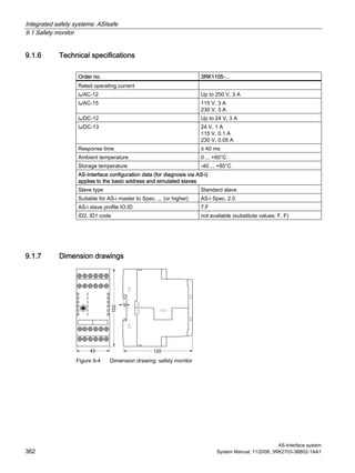
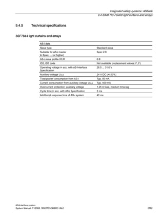
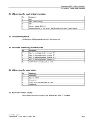
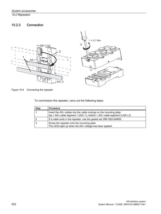
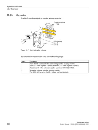
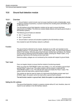
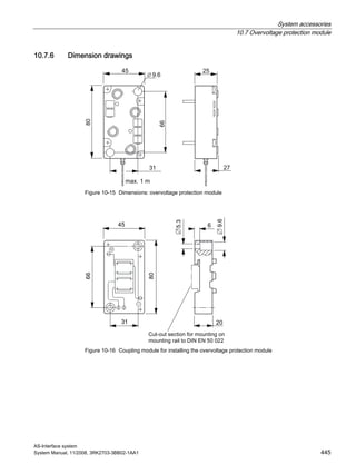
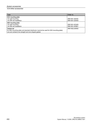
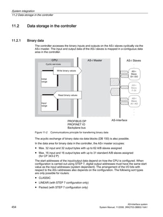
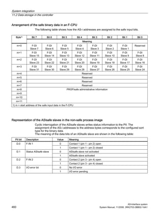
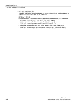
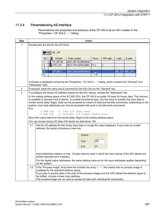
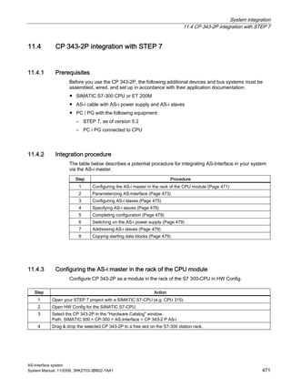
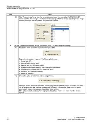
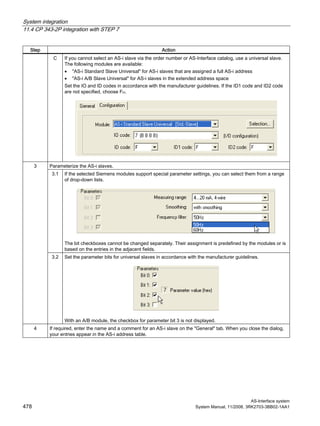
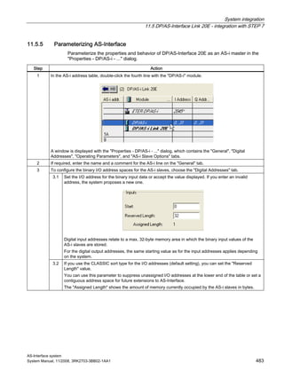
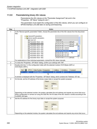
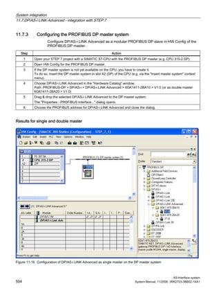
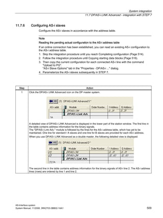
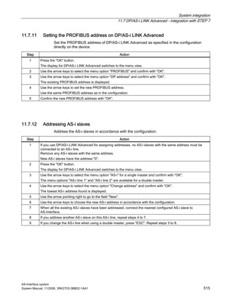
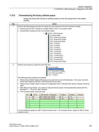
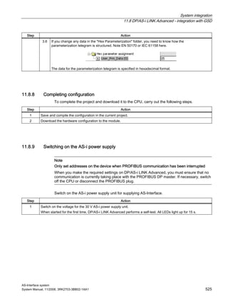
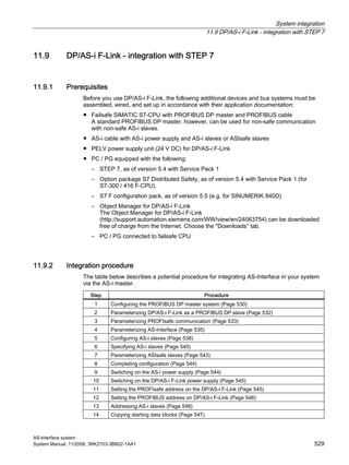
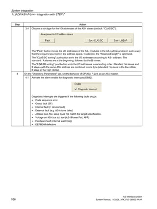
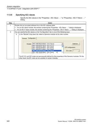
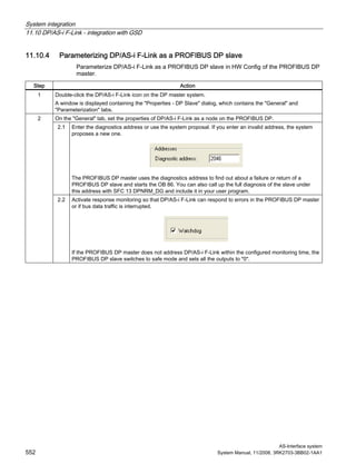
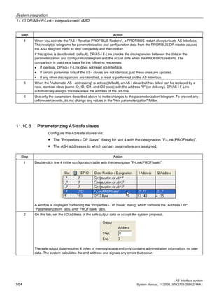
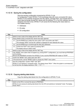
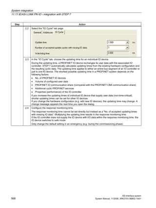
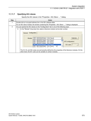
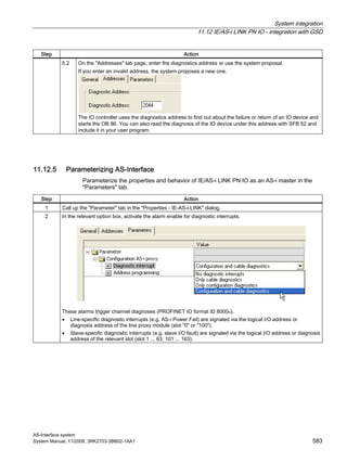
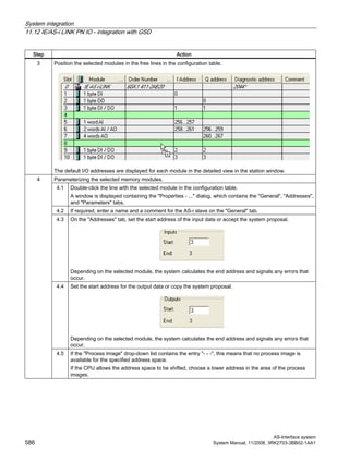
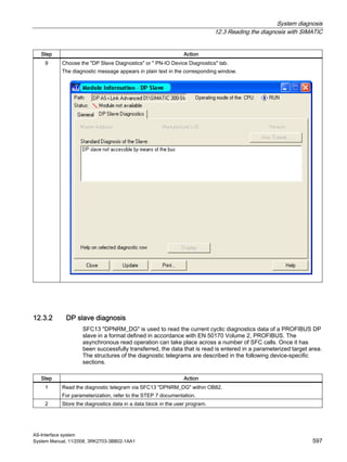
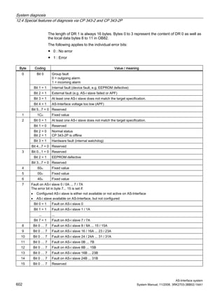
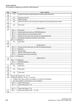
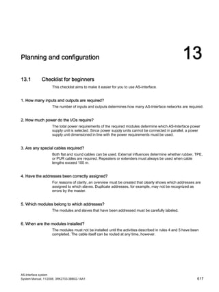
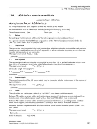
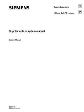
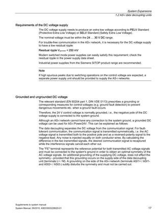
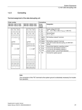
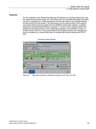
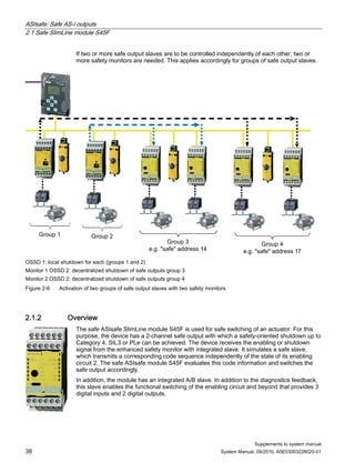
11.11.5 Parameterizing AS-Interface
Parameterize the properties and behavior of IE/AS-i LINK PN IO as an AS-i master in the
"Properties - IE/AS-i ..." dialog.
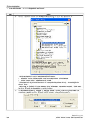
Step Action
1 Double-click the line "[1]" in the AS-i address table.
A window is displayed containing the "Properties - IE-ASi-Link-1M" (for single master) or "Properties -
IE-ASi-Link-2M" (for double master), which contains the "General", "Addresses", and "Pack" tab pages.
The following settings relate to IE-AS-i LINK PN IO as a single master or to AS i line 1 of a double master.
2 If required, enter the name and a comment for the AS-i line on the "General" tab.
The name for line 1 is identical to the device name of the IE-AS-i LINK (can be set by double-clicking the
IE-AS-i LINK PN IO icon on the IO system; see description above).
3 Set the diagnostics address of the line proxy on the "Addresses" tab page.
This diagnostics address is used to indicate an incoming/outgoing line-specific diagnostic alarm (e.g. AS-i
power failure, ground fault, redundant slave) via the OB82 diagnostics block. The system function block SFB54
"RALRM" can be used to call up additional diagnostic information. This procedure is described in the
IE/AS-i LINK PN IO Manual under section 9.2.2 "Diagnostic alarms".
4 On the "Parameters" tab page, set the IE-AS-i LINK PN IO as an AS-i master.
In particular, the diagnostic alarms must be enabled so that the OB82 can be called up if an error occurs.
When you choose the "Automatic address programming" option (default), an AS-i slave that has failed can be
replaced by a new, identical slave with the address "0" (as-delivered condition) and the IE-AS-i LINK PN IO
automatically assigns the address of the slave that has failed to the new slave.
If this option is deactivated, you have to assign the address manually to the new slave when the slave is
replaced.
5 When a double master is used, double-click the line "[2]" in the AS-i address table and repeat steps 1 to 4 for
AS-i line 2.](https://image.slidesharecdn.com/uabv6w96sd2atwahrqps-signature-8cf552cbae5741209e73d76315d6227712e4af3c534b4de5ef70d54611ba47f4-poli-150402172610-conversion-gate01/85/As-interface-system-manual-2008-11_x-2010-09_en-us-569-320.jpg)
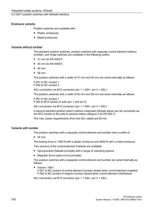
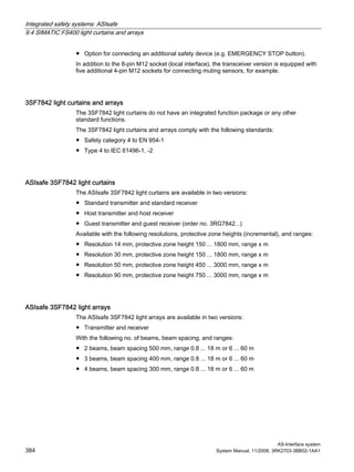
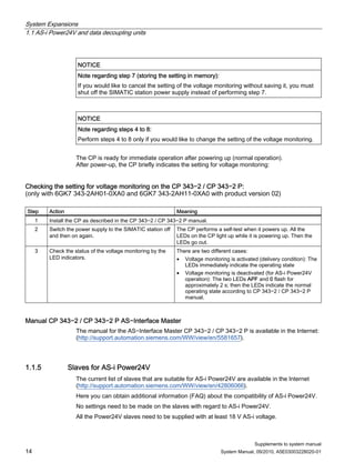
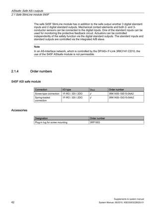
![System integration
11.11 IE/AS-i LINK PN IO - integration with STEP 7
AS-Interface system
570 System Manual, 11/2008, 3RK2703-3BB02-1AA1
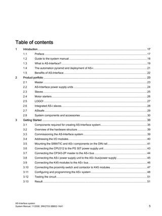
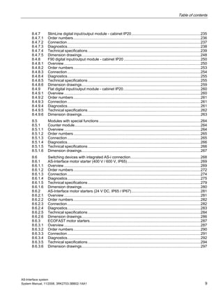
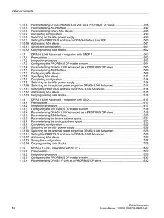
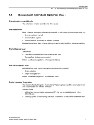
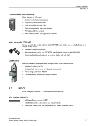
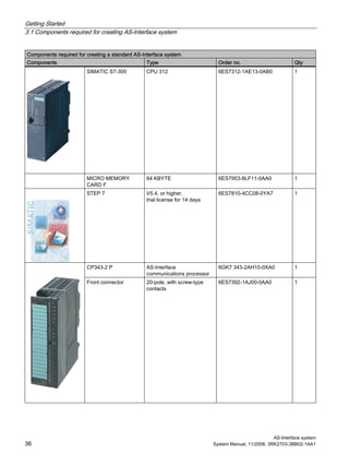
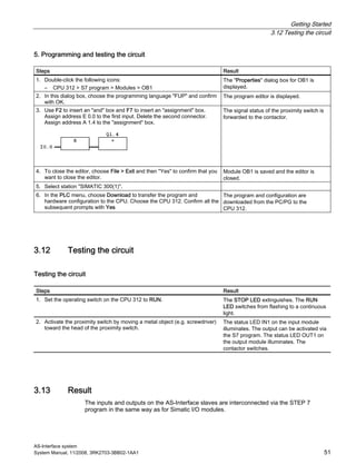
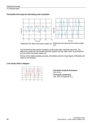
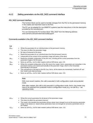
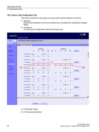
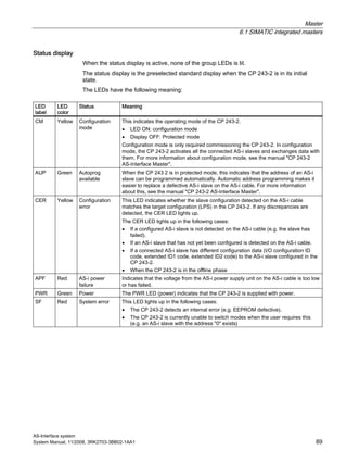
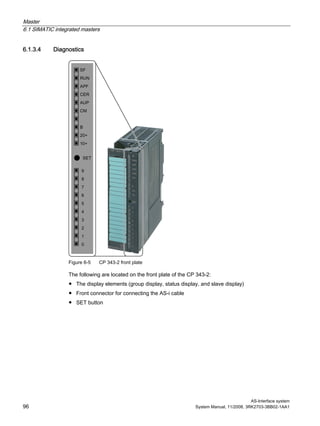
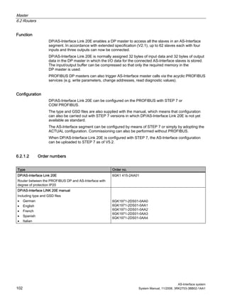
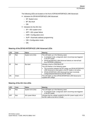
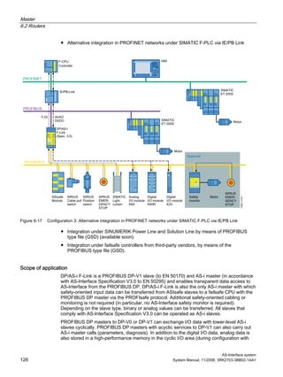
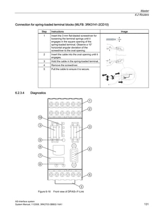
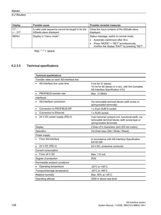
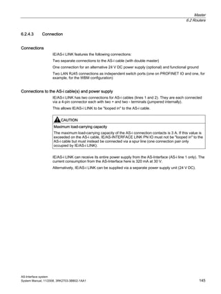
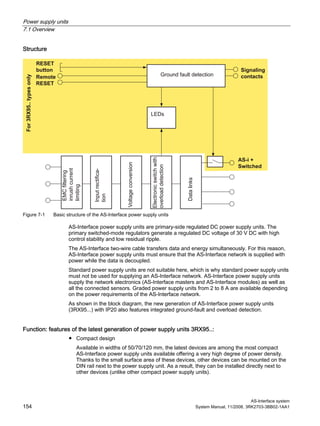
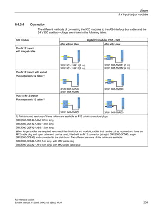
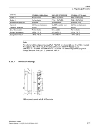
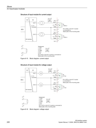
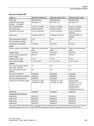
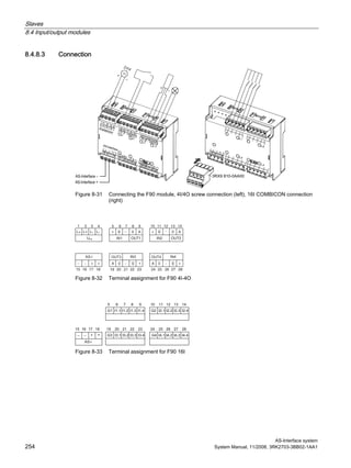
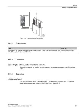
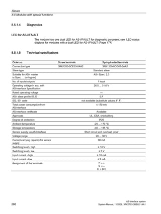
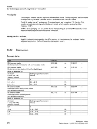
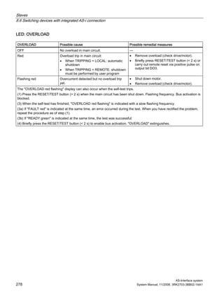
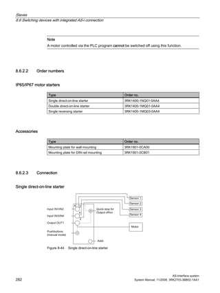
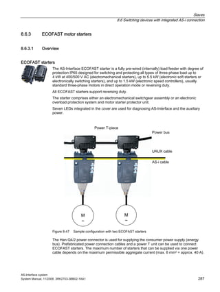
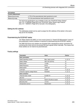
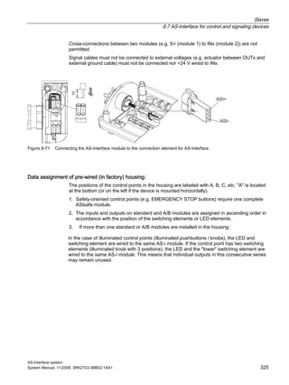
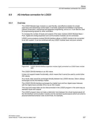
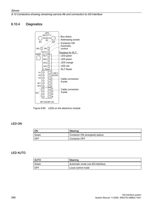
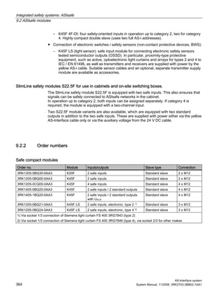
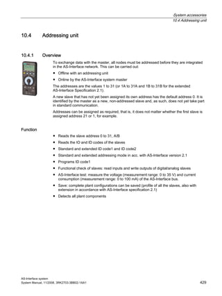
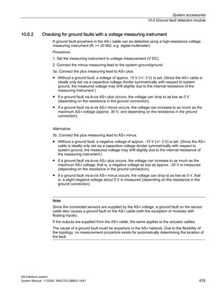
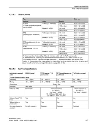
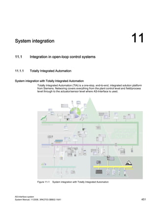
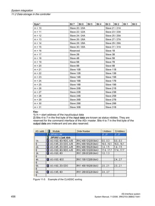
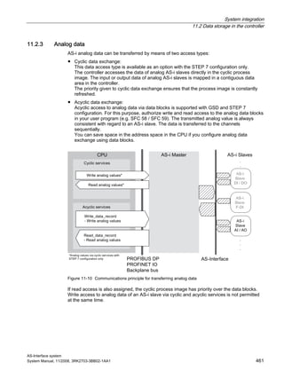
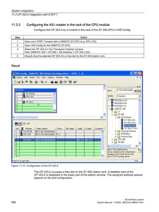
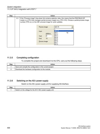
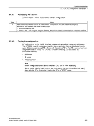
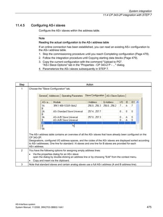
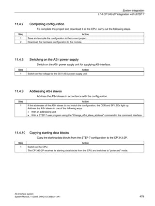
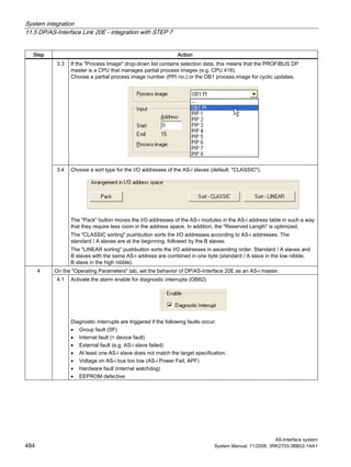
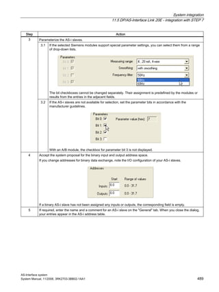
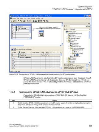
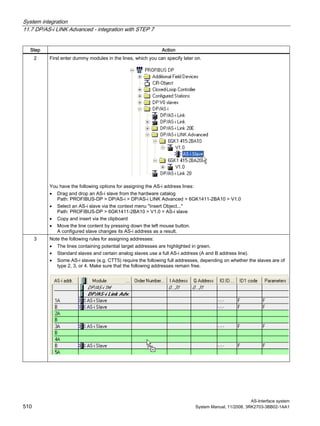
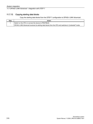
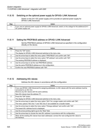
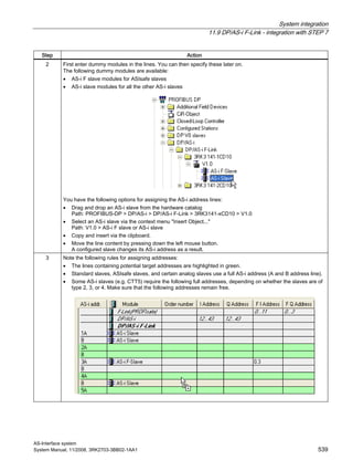
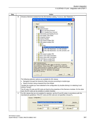
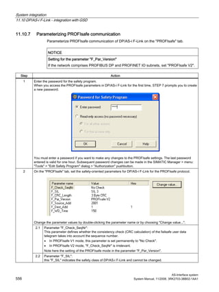
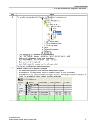
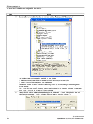
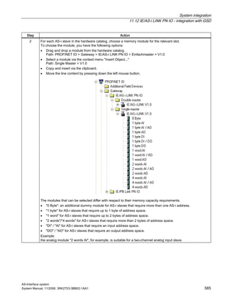
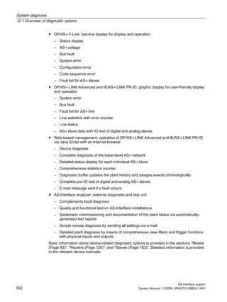
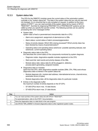
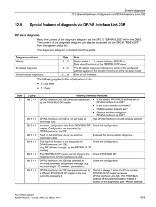
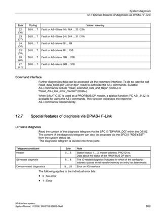
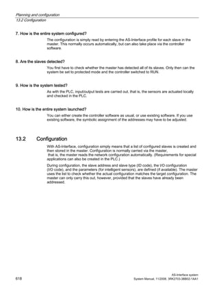
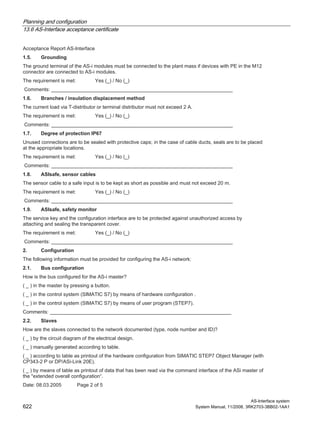
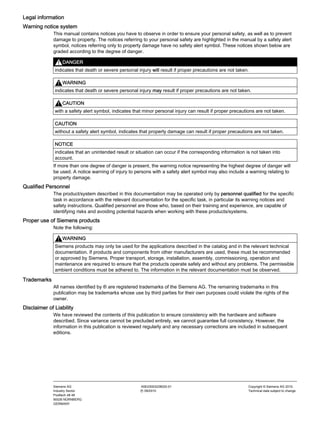
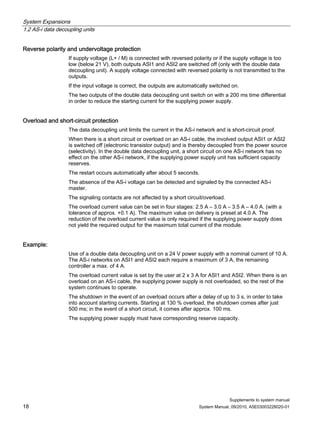
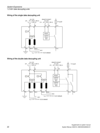
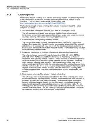
11.11.6 Configuring AS-i slaves
Configure the AS-i slaves within the address table.
Note
Reading the actual configuration to the AS-i address table
If an online connection has been established, you can read an existing AS-i configuration to
the AS-i address table.
1. Skip the integration procedure until you reach Completing configuration (Page 576).
2. Follow the integration procedure until Addressing AS-i slaves (Page 577).
3. Then copy the current configuration for each connected AS-i line with the command
"Download to PG".
"AS-i Slave Optionss" tab in the "Properties - IE/AS-i ..." dialog.
4. Parameterize the AS-i slaves subsequently in STEP 7.
Step Action
1 Click the icon for IE/AS-i LINK PN IO on the IO system.
A detailed view of IE-AS i LINK PN IO is displayed in the lower part of the station window.
An AS-i slave can be configured for each AS-i address (1A, B, 2A, B, and so on).
When you use IE/AS-i LINK PN IO as a double master, the following detailed view is displayed: The number of
the AS-i line ("[1]:..." or "[2]:...") is also displayed in square parentheses next to each AS-i address:
All the AS-i address lines contain dummy modules (AS-i proxy slave) as standard.](https://image.slidesharecdn.com/uabv6w96sd2atwahrqps-signature-8cf552cbae5741209e73d76315d6227712e4af3c534b4de5ef70d54611ba47f4-poli-150402172610-conversion-gate01/85/As-interface-system-manual-2008-11_x-2010-09_en-us-570-320.jpg)


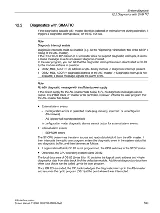


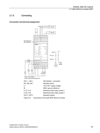

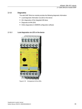

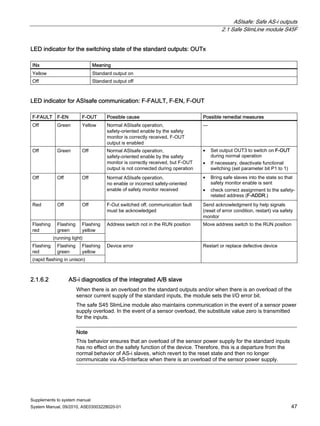

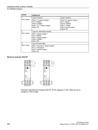
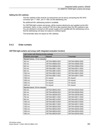
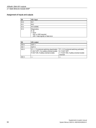
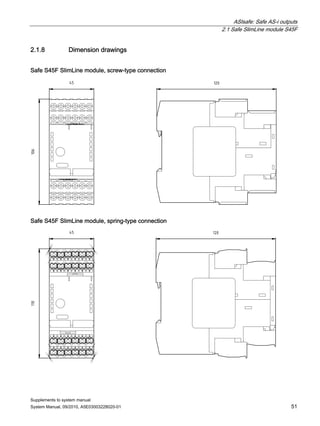
![ASIsafe: Safe AS-i outputs
2.1 Safe SlimLine module S45F
Supplements to system manual
System Manual, 09/2010, A5E03003228020-01 49
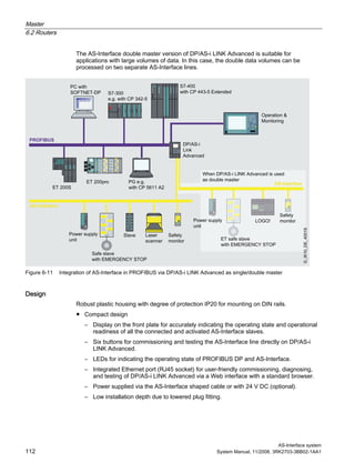
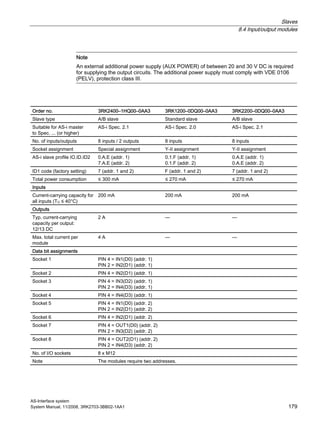
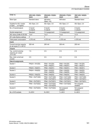
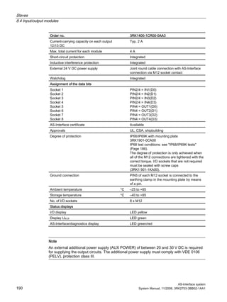
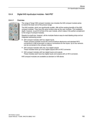
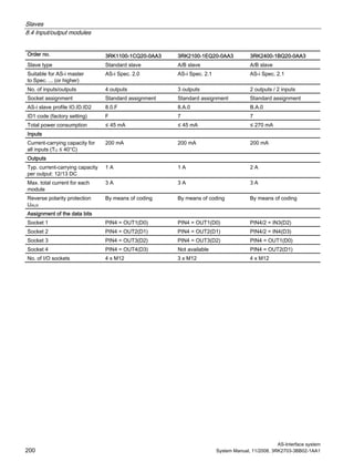
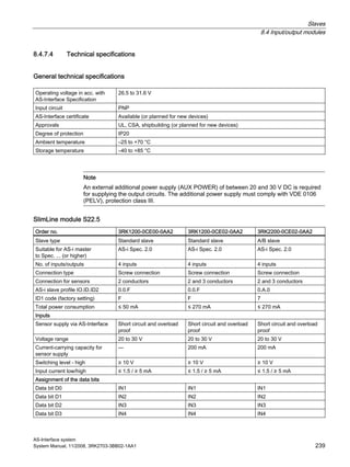
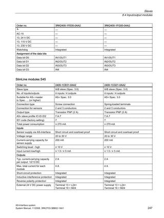
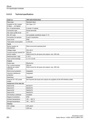
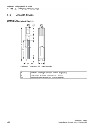
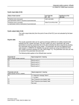
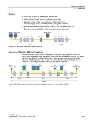
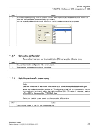
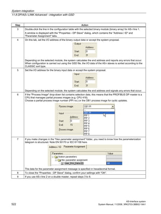
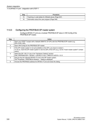
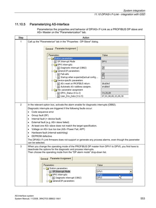
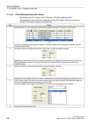
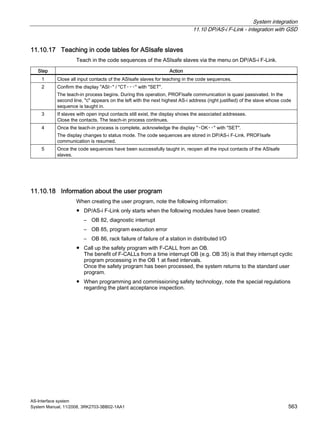
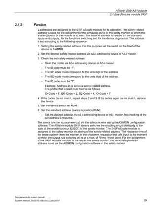
2.1.7 Technical data
Order number 3RK1405-1SE15-0AA2 3RK1405-1SG15-0AA2
Type of connection Screw-type connection Spring-loaded connection
Slave type Standard slave
Suitable for AS-i Master
acc. to spec. ... (or higher)
AS-i Spec. 2.1
AS-i slave profile IO.ID.ID2 S-7.A.E (ID1 is variable, default setting: 7hex)
PFH value 2.14 x 10⁻⁸ [1/h]
No. of inputs/outputs 1 safe output / 3 inputs digital / 2 outputs digital
Electrical data
Total power consumption ≤ 200 mA
Reverse polarity protection Integrated
Total system response time (from the
moment of the shutdown request to
the moment at which the output has
switched off)
< 70 ms
On-delay time (Power On) < 3 s
Digital inputs
For signal "0" Iin ≤ 1.5 mA
For signal "1" Uin, Iin ≥ 10 V, ≥ 5 mA
Digital outputs (short-circuit-proof, with induction protection)
Operating voltage UAUX (PELV) 24 V ± 15 %
Current-carrying capacity per output
Iout
≤ 0.7 A, short-circuit-proof and overload-proof
Voltage drop Δ Utype 0.8 V
Safe output
Max. contact load 24 V DC, 3 A
Protection external with 4 A MT, max.
Mechanical data
Degree of protection IP20
Rated temperature Ta 25 °C
Ambient temperature Ta -25 ... +70 °C
Storage temperature Ts -40 ... +85 °C
Approvals UL, CSA applied for
For information on additional properties, please refer to the current data sheet which is
available in the Internet:
Order No.:
3RK1405-1SE15-0AA2 (http://support.automation.siemens.com/WW/view/en/3RK1405-1SE15-0AA2/td)
3RK1405-1SG15-0AA2 (http://support.automation.siemens.com/WW/view/en/3RK1405-1SG15-0AA2/td)](https://image.slidesharecdn.com/uabv6w96sd2atwahrqps-signature-8cf552cbae5741209e73d76315d6227712e4af3c534b4de5ef70d54611ba47f4-poli-150402172610-conversion-gate01/85/As-interface-system-manual-2008-11_x-2010-09_en-us-683-320.jpg)


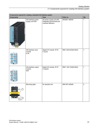
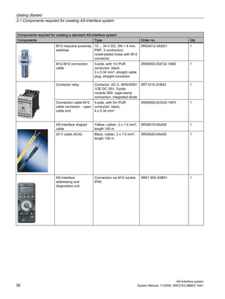
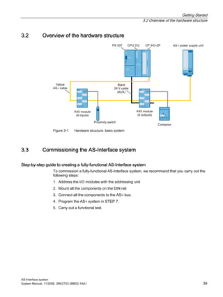
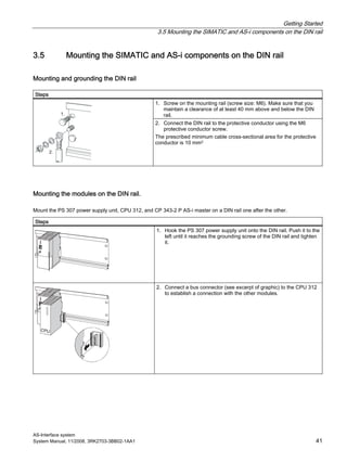
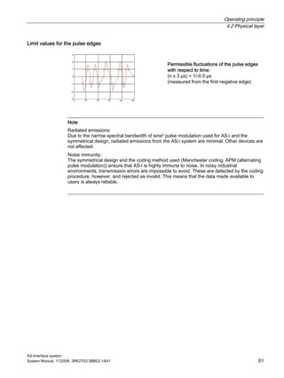
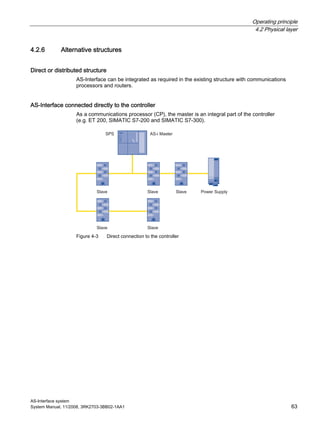
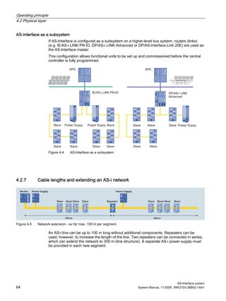
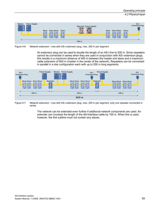
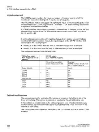
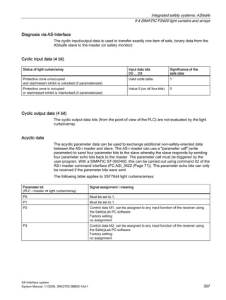
This document provides an overview of the AS-Interface system, including its components, configuration, and operation. It describes the product portfolio, hardware setup, commissioning process, and physical/data link layers. The document also covers masters, power supplies, slaves, modules, diagnostics, and technical specifications. It aims to explain everything needed to understand and implement an AS-Interface network.


