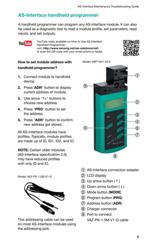
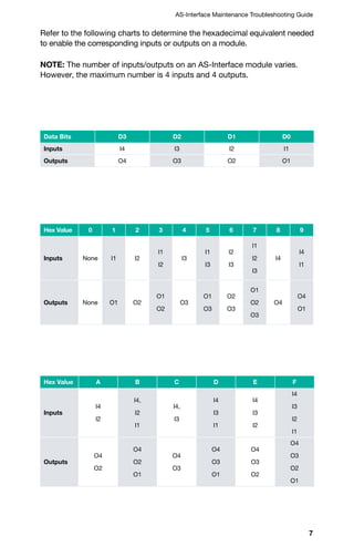
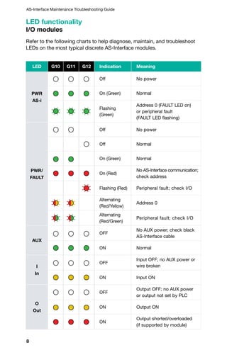
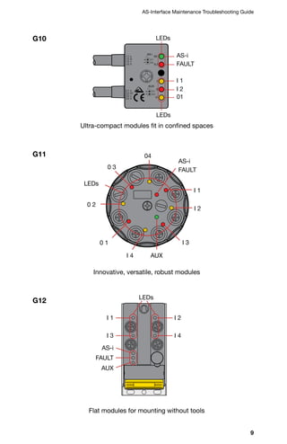
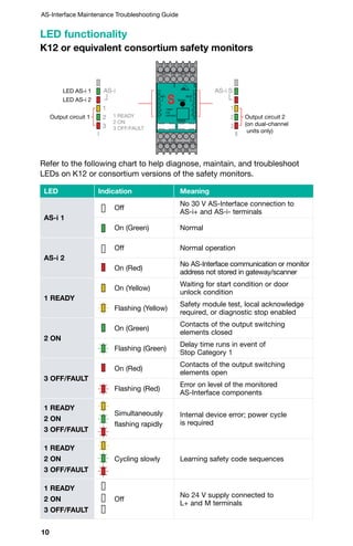
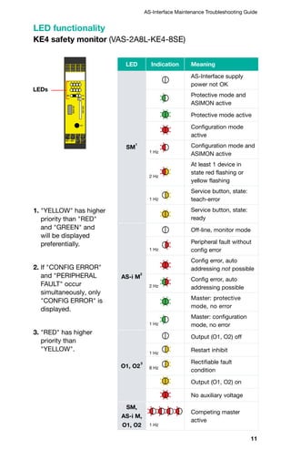
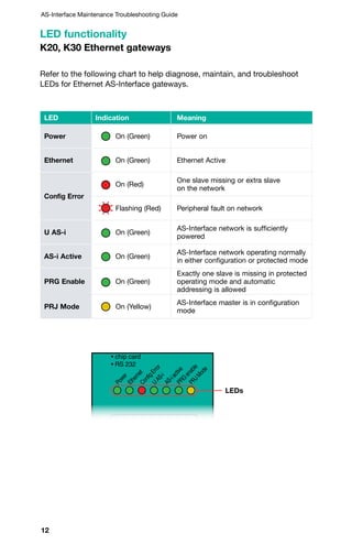
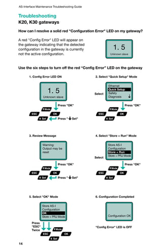
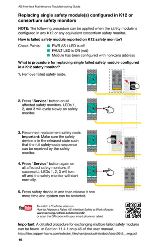
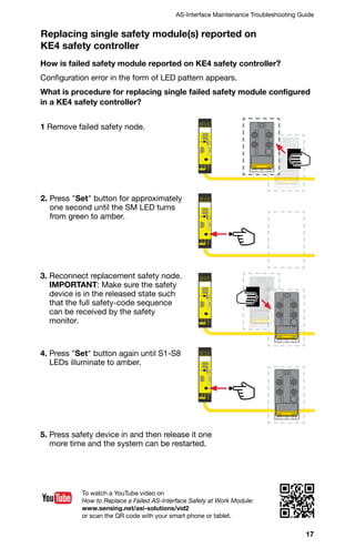
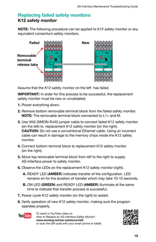
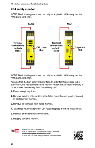
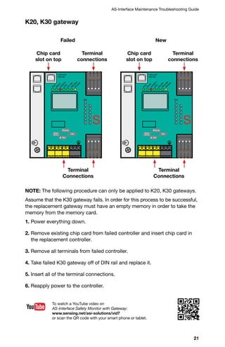
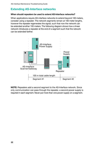
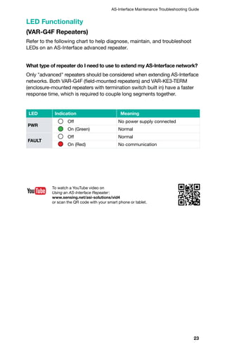
SlideShare a Scribd company logo
1 of 36
Download to read offline
AS-Interface
Maintenance
Troubleshooting
Guide
Edition 4
2
Visit www.pepperl-fuchs.us for datasheets, manuals, software
tools, newsletters, and product cross reference.
www.youtube.com/PepperlFuchsUSA
Visit our YouTube channel for informative videos.
www.twitter.com/PepperlFuchsUSA
Follow us on Twitter.
G10 ultra-compact module–the perfect solution for space-limited applications.
3
AS-Interface Maintenance Troubleshooting Guide
Contents
AS-Interface handheld programmer	 5 - 7
	 How to set module address with handheld programmer	 5
	 How to read module profile with handheld programmer	 6
	 How to read inputs and set outputs on AS-Interface module(s)	 6
LED functionality	 8 - 12
	 I/O modules	 8
	 K12 or equivalent consortium safety monitors	 10
	 KE4 safety monitor	 11
	 K20, K30 Ethernet gateways	 12
Troubleshooting	 13 - 14
	 K20, K30 gateways	 13 - 14
	 Replacing failed modules	 15 - 18
Replacing failed standard module(s)	 15
	 Replacing single safety module(s) configured in K12
	 or consortium safety monitors	 16
	 Replacing single safety module(s) reported on KE4 safety controller	 17
	 Replacing single safety module(s) reported on K30 gateway	 18
Replacing failed safety monitors	 19 - 21
	 K12 safety monitor	 19
	 KE4 safety monitor	 20
	 K20, K30 gateway	 21
Extending AS-Interface networks	 22 - 24
Built-In advanced diagnostics K20, K30 gateways	 25 - 26
Power supplies	 27 - 28
Helpful wiring hints	 29 - 34
Common problems and solutions	 35
4
AS-Interface Maintenance Troubleshooting Guide
AS-Interface – Economical, Easy, and High Performing
AS-Interface minimizes installation effort, has a comprehensive
diagnostic function, and enables flexible system enhancements.
AS-Interface is an open installation system that is recognized
and accepted around the world. Pepperl+Fuchs and many
manufacturers offer a wide range of compatible products.
5
AS-Interface Maintenance Troubleshooting Guide
A handheld programmer can program any AS-Interface module. It can also
be used as a diagnostic tool to read a module profile, set parameters, read
inputs, and set outputs.
How to set module address with
handheld programmer?
1. Connect module to handheld
device.
2. PressADR button to display
current address of module.
3. Use arrow hi buttons to
choose new address.
4. Press PRG button to set
the address.
5. Press ADR button to confirm
new address got stored.
AS-Interface handheld programmer
1 AS-Interface connection adapter
2 LCD display
3 Up arrow button ( h )
4 Down arrow button ( i )
5 Mode button (MODE)
6 Program button (PRG)
7 Address button (ADR)
8 Charger connector
9 Port to connect
VAZ-PK-1.5M-V1-G cable
2
3
4
6
7
8
5
9
1
YouTube video available on How to Use AS-Interface
Handheld Programmer:
visit: http://www.sensing.net/asi-solutions/vid1
or scan the QR code with your smart phone or tablet.
Model: VBP-HH1-V3.0
Model: VAZ-PK-1.5M-V1-G
All AS-Interface modules have
profiles. Typically, module profiles
are made up of ID, ID1, ID2, and IO.
NOTE: Certain older modules
(AS-Interface specification 2.0)
may have reduced profiles
with only ID and IO.
This addressing cable can be used
on most AS-Interface modules using
the addressing jack.
6
AS-Interface Maintenance Troubleshooting Guide
1. Connect module to handheld device.
2. Press ADR button.
3. Press MODE button each time to see the corresponding values that
make up the module profile.
			ID 	 ID1 	 ID2 	 IO
During commissioning of an installation, you can check inputs or set
outputs on an AS-Interface module.
1. Connect module to handheld device.
2. Press ADR button.
3. Change mode to DATA by pressing the MODE button 4x or 7x
depending on module type. (Menu will repeat if you go too far.)
4. Use arrow h i buttons to select output value.
5. Press and hold PRG button to turn outputs on.
6. Press and hold ADR button to read inputs.
How to read module profile with handheld programmer?
How to read inputs and set outputs on AS-Interface module(s)?
7
AS-Interface Maintenance Troubleshooting Guide
Refer to the following charts to determine the hexadecimal equivalent needed
to enable the corresponding inputs or outputs on a module.
NOTE: The number of inputs/outputs on an AS-Interface module varies.
However, the maximum number is 4 inputs and 4 outputs.
Data Bits D3 D2 D1 D0
Inputs I4 I3 I2 I1
Outputs O4 O3 O2 O1
Hex Value 0 1 2 3 4 5 6 7 8 9
Inputs None I1 I2
I1
I2
I3
I1
I3
I2
I3
I1
I2
I3
I4
I4
I1
Outputs None O1 O2
O1
O2
O3
O1
O3
O2
O3
O1
O2
O3
O4
O4
O1
Hex Value A B C D E F
Inputs
I4
I2
I4,
I2
I1
I4,
I3
I4
I3
I1
I4
I3
I2
I4
I3
I2
I1
Outputs
O4
O2
O4
O2
O1
O4
O3
O4
O3
O1
O4
O3
O2
O4
O3
O2
O1
8
AS-Interface Maintenance Troubleshooting Guide
LED G10 G11 G12 Indication Meaning
PWR
AS-i
Off No power
On (Green) Normal
Flashing
(Green)
Address 0 (FAULT LED on)
or peripheral fault
(FAULT LED flashing)
PWR/
FAULT
Off No power
Off Normal
On (Green) Normal
On (Red)
No AS-Interface communication;
check address
Flashing (Red) Peripheral fault; check I/O
Alternating
(Red/Yellow)
Address 0
Alternating
(Red/Green)
Peripheral fault; check I/O
AUX
OFF
No AUX power; check black
AS-Interface cable
ON Normal
I
In
OFF
Input OFF; no AUX power or
wire broken
ON Input ON
O
Out
OFF
Output OFF; no AUX power
or output not set by PLC
ON Output ON
ON
Output shorted/overloaded
(if supported by module)
Refer to the following charts to help diagnose, maintain, and troubleshoot
LEDs on the most typical discrete AS-Interface modules.
LED functionality
I/O modules
9
AS-Interface Maintenance Troubleshooting Guide
AS-i
LEDs
FAULT
I 2
I 1
I 3
0 3
0 2
0 1
AUXI 4
04
Ultra-compact modules fit in confined spaces
Innovative, versatile, robust modules
Flat modules for mounting without tools
G10
G11
G12
2.1:
2.2: O1
AS-i
3.1
3.2
AUX
4.1
4.2
1.1:
1.2: I2
+
1.3: –
1.4: I1
AS-I
FLT
I1
O1
I2
+
–
+
–
2.3:
+
–
2.4: I1
AS-i
LEDs
LEDs
FAULT
I 1
I 2
01
AS-i
LEDs
FAULT
AUX
I 1 I 2
I 4I 3
10
AS-Interface Maintenance Troubleshooting Guide
Refer to the following chart to help diagnose, maintain, and troubleshoot
LEDs on K12 or consortium versions of the safety monitors.
LED functionality
K12 or equivalent consortium safety monitors
LED Indication Meaning
AS-i 1
Off
No 30 V AS-Interface connection to
AS-i+ and AS-i- terminals
On (Green) Normal
AS-i 2
Off Normal operation
On (Red)
No AS-Interface communication or monitor
address not stored in gateway/scanner
1 READY
On (Yellow)
Waiting for start condition or door
unlock condition
Flashing (Yellow)
Safety module test, local acknowledge
required, or diagnostic stop enabled
2 ON
On (Green)
Contacts of the output switching
elements closed
Flashing (Green)
Delay time runs in event of
Stop Category 1
3 OFF/FAULT
On (Red)
Contacts of the output switching
elements open
Flashing (Red)
Error on level of the monitored
AS-Interface components
1 READY
2 ON
3 OFF/FAULT
Simultaneously
flashing rapidly
Internal device error; power cycle
is required
1 READY
2 ON
3 OFF/FAULT
Cycling slowly Learning safety code sequences
1 READY
2 ON
3 OFF/FAULT
Off
No 24 V supply connected to
L+ and M terminals
AS-i AS-i S
1
2
3
I II
1
2
3
1 READY
2 ON
3 OFF/FAULT
LED AS-i 1
Output circuit 1 Output circuit 2
(on dual-channel
units only)
LED AS-i 2
AS-i AS-i S
1
2
3
I II
1
2
3
1 READY
2 ON
3 OFF/FAULT
LED AS-i 1
Output circuit 1 Output circuit 2
(on dual-channel
units only)
LED AS-i 2
AS-i
Service
1
2
1
2
3 3
CONFIG
1 READY
2 ON
3 OFF/FAULT
1.13 1.23 1.Y1
1.Y2
2.13 2.23 2.Y1
2.Y2
L+ M 1.32 2.32
1.14 1.24 FE 2.14 2.24
AS-iS
+ AS-iS -+ AS-i -
11
AS-Interface Maintenance Troubleshooting Guide
1. YELLOW has higher
priority than RED
and GREEN and
will be displayed
preferentially.
2. If CONFIG ERROR
and PERIPHERAL
FAULT occur
simultaneously, only
CONFIG ERROR is
displayed.
3. RED has higher
priority than
YELLOW.
LED functionality
KE4 safety monitor (VAS-2A8L-KE4-8SE)
LEDs
LED Indication Meaning
SM
1
AS-Interface supply
power not OK
Protective mode and
ASIMON active
Protective mode active
Configuration mode
active
Configuration mode and
ASIMON active
At least 1 device in
state red flashing or
yellow flashing
Service button, state:
teach-error
Service button, state:
ready
AS-i M
2
Off-line, monitor mode
Peripheral fault without
config error
Config error, auto
addressing not possible
Config error, auto
addressing possible
Master: protective
mode, no error
Master: configuration
mode, no error
O1, O2
3
Output (O1, O2) off
Restart inhibit
Rectifiable fault
condition
Output (O1, O2) on
No auxiliary voltage
SM,
AS-i M,
O1, O2
Competing master
active
1 Hz
1 Hz
1 Hz
1 Hz
1 Hz
8 Hz
1 Hz
2 Hz
2 Hz
12
AS-Interface Maintenance Troubleshooting Guide
Mode
Power
EthernetConfigError
U
AS-i
AS-iactivePRG
enable
PRJMode
Aux
1.Y1
2.Y1
1.Y2
2.Y2
K1
K4
K3
K2
• chip card
• RS 232
Refer to the following chart to help diagnose, maintain, and troubleshoot
LEDs for Ethernet AS-Interface gateways.
LED Indication Meaning
Power On (Green) Power on
Ethernet On (Green) Ethernet Active
Config Error
On (Red)
One slave missing or extra slave
on the network
Flashing (Red) Peripheral fault on network
U AS-i On (Green)
AS-Interface network is sufficiently
powered
AS-i Active On (Green)
AS-Interface network operating normally
in either configuration or protected mode
PRG Enable On (Green)
Exactly one slave is missing in protected
operating mode and automatic
addressing is allowed
PRJ Mode On (Yellow)
AS-Interface master is in configuration
mode
LED functionality
K20, K30 Ethernet gateways
LEDs
13
AS-Interface Maintenance Troubleshooting Guide
What are the two most common error codes on the gateway 2-digit,
7-segment display?
40 – Offline phase: Gateway displays OFF-LINE by host
Check Points
	 n No power to AS-Interface network, causing it to be offline
	 n Network has been taken offline manually using gateway display
or toggling F0 bit in the PLC output image.
41 – Detection phase: Gateway remains in this state until at least one
node is found.
Check Points
n Place nodes on network, making sure there are no duplicate
addresses.
n Check to ensure that exactly one power supply is used for each
AS-Interface segment.
HINT: This can be easily verified by powering down each of the
AS-Interface power supplies, one at a time.
	 	 •  The PWR LEDs on all of the nodes within each segment
should turn off.
	 	 •  The U-AS-i LED on the segment connected to the
AS-Interface gateway/scanner should turn off.
n Make sure the AS-Interface power supply is not being used to
power auxiliary devices.
HINT: Disconnect the auxiliary power supply.
	 	 •  Walk around to every AS-Interface node and make sure that
the AUX LED is off
Troubleshooting
K20, K30 gateways
14
AS-Interface Maintenance Troubleshooting Guide
Use the six steps to turn off the red “Config Error” LED on the gateway
1. Config Error LED ON
3. Review Message
5. Select OK Mode
2. Select Quick Setup Mode
4. Select Store + Run Mode
6. Configuration Completed
Config Error LED is OFF
Press OK
Select
Select
Press OK
Press
ESC
Twice
Press OK
Press OK
Press  Set
Press  Set
OKESC
Mode
Set
OKESC
Mode
Set
OKESC
Mode
Set
OKESC
Mode
Set
OKESC
Mode
Set
Ethernet
Quick Setup
Safety
Diagnosis
Store AS-I
Configuration
Store + Run
Store + PRJ Mode
Configuration OK
Store AS-I
Configuration
OK
Store + PRJ Mode
Warning:
Output may be
reset
1. 5
Unknown slave
How can I resolve a solid red Configuration Error LED on my gateway?
Troubleshooting
K20, K30 gateways
1. 5
Unknown slave
A red Config Error LED will appear on
the gateway indicating that the detected
configuration in the gateway is currently
not the active configuration.
15
AS-Interface Maintenance Troubleshooting Guide
Replacing failed module(s)
Replacing failed standard modules
IMPORTANT: Making sure module profile(s) are identical is critical when
replacing failed modules. The new module profile must be identical to the
failed module. This includes: ID, ID1, ID2, and IO values. It also must be set
to address 0 before connection.
How to replace a single failed node?
	 1. Remove failed module.
	 2. Connect new module.
How to replace multiple failed nodes?
	 1. Remove all failed modules.
	 2. Connect the handheld programmer and manually assign addresses
to all but one replacement module.
	 3. The last replacement module can receive its address automatically.
16
AS-Interface Maintenance Troubleshooting Guide
NOTE: The following procedure can be applied when the safety module is
configured in any K12 or any equivalent consortium safety monitor.
How is failed safety module reported on K12 safety monitor?
Check Points:	 n PWR AS-I LED is off
	 	 n FAULT LED is ON (red)
	 	 n Module has been configured with non-zero address
What is procedure for replacing single failed safety module configured
in a K12 safety monitor?
Replacing single safety module(s) configured in K12 or
consortium safety monitors
2. Press Service button on all
affected safety monitors. LEDs 1,
2, and 3 will cycle slowly on safety
monitor.
1. Remove failed safety node.
4. Press Service button again on
all affected safety monitors. If
successful, LEDs 1, 2, 3 will turn
off and the safety monitor will start
normally.
5. Press safety device in and then release it one
more time and system can be restarted.
3. Reconnect replacement safety node.
Important: Make sure the safety
device is in the released state such
that the full safety-code sequence
can be received by the safety
monitor.
AS-i
Service
1
2
1
2
3 3
CONFIG
1 READY
2 ON
3 OFF/FAULT
1.13 1.23 1.Y1
1.Y2
2.13 2.23 2.Y1
2.Y2
L+ M 1.32 2.32
1.14 1.24 FE 2.14 2.24
AS-iS
+ AS-iS -+ AS-i -
AS-i
Service
1
2
1
2
3 3
CONFIG
1 READY
2 ON
3 OFF/FAULT
1.13 1.23 1.Y1
1.Y2
2.13 2.23 2.Y1
2.Y2
L+ M 1.32 2.32
1.14 1.24 FE 2.14 2.24
AS-iS
+ AS-iS -+ AS-i -
AS-i
Service
1
2
1
2
3 3
CONFIG
1 READY
2 ON
3 OFF/FAULT
1.13 1.23 1.Y1
1.Y2
2.13 2.23 2.Y1
2.Y2
L+ M 1.32 2.32
1.14 1.24 FE 2.14 2.24
AS-iS
+ AS-iS -+ AS-i -
AS-i
Service
1
2
1
2
3 3
CONFIG
1 READY
2 ON
3 OFF/FAULT
1.13 1.23 1.Y1
1.Y2
2.13 2.23 2.Y1
2.Y2
L+ M 1.32 2.32
1.14 1.24 FE 2.14 2.24
AS-iS
+ AS-iS -+ AS-i -
Important: A detailed procedure for exchanging multiple failed safety modules
can be found in Section 11.4.1 on p 45 of the user manual.
http://files.pepperl-fuchs.com/selector_files/navi/productInfo/doct/tdoct3645__eng.pdf
To watch a YouTube video on
How to Replace a Failed AS-Interface Safety at Work Module:
www.sensing.net/asi-solutions/vid2
or scan the QR code with your smart phone or tablet.
17
AS-Interface Maintenance Troubleshooting Guide
Replacing single safety module(s) reported on
KE4 safety controller
How is failed safety module reported on KE4 safety controller?
Configuration error in the form of LED pattern appears.
What is procedure for replacing single failed safety module configured
in a KE4 safety controller?
2. Press Set button for approximately
one second until the SM LED turns
from green to amber.
1 Remove failed safety node.
4. Press Set button again until S1-S8
LEDs illuminate to amber.
5. Press safety device in and then release it one
more time and the system can be restarted.
3. Reconnect replacement safety node.
IMPORTANT: Make sure the safety
device is in the released state such
that the full safety-code sequence
can be received by the safety
monitor.
To watch a YouTube video on
How to Replace a Failed AS-Interface Safety at Work Module:
www.sensing.net/asi-solutions/vid2
or scan the QR code with your smart phone or tablet.
18
AS-Interface Maintenance Troubleshooting Guide
How is failed safety module reported on K30 gateway?
Graphic display on gateway reports a x.x missing slave error even though
the module is on the network.
What is procedure for replacing single failed safety module configured
in a K30 gateway?
Replacing single safety module(s) reported on K30 gateway
1. Remove failed safety node.
2. Reconnect replacement safety node.
3. Display reports: safety error-emergency shutdown
NOTE: This is displayed due to new and old safety module coding
sequences differing.
4. Press OK.
5. Drill down to AS-I Safety. Select OK.
6. Teach Safety. Select OK.
7. Select Single Slave.
8. Select the network on which the replacement module will reside.
9. Select the address for the failed safety node that needs to be retaught.
10. Press the safety device in and then release it one more time to restart
the system.
To watch a YouTube video on
How to Replace a Failed AS-Interface Safety at Work Module:
www.sensing.net/asi-solutions/vid2
or scan the QR code with your smart phone or tablet.
19
AS-Interface Maintenance Troubleshooting Guide
Replacing failed safety monitors
K12 safety monitor
Failed New
NOTE: The following procedure can be applied to K12 safety monitor or any
equivalent consortium safety monitors.
Assume that the K12 safety monitor on the left has failed.
IMPORTANT: In order for this process to be successful, the replacement
safety monitor must be new or unvalidated.
1. Power everything down.
2. Remove bottom removable terminal block from the failed safety monitor.
NOTE: The removable terminal block connected to L1+ and M.
3. Use VAS-SIMON-RJ45 jumper cable to connect failed K12 safety monitor
(on the left) to replacement K12 safety monitor (on the right).
CAUTION: Do not use a conventional Ethernet cable. Using an incorrect
cable can result in damage to the memory chips inside the K12 safety
monitor.
4. Connect bottom terminal block to replacement K12 safety monitor
(on the right).
5. Move top removable terminal block from left to the right to supply
AS-Interface power to safety monitor.
6. Observe the LEDs on the replacement K12 safety monitor (right).
	 A. READY LED (AMBER) indicates transfer of the configuration. LED
remains on for the duration of transfer which may take 10-15 seconds.
	 B. ON LED (GREEN) and READY LED (AMBER) illuminate at the same
time to indicate that transfer process is successful.
7. Power cycle K12 safety monitor (on the right) to restart.
8. Verify operation of new K12 safety monitor, making sure the program
operates properly.
To watch a YouTube video on
How to Replace an AS-Interface Safety Monitor:
www.sensing.net/asi-solutions/vid3
or scan the QR code with your smart phone or tablet.
AS-i
Service
1
2
1
2
3 3
CONFIG
1 READY
2 ON
3 OFF/FAULT
1.13 1.23 1.Y1
1.Y2
2.13 2.23 2.Y1
2.Y2
L+ M 1.32 2.32
1.14 1.24 FE 2.14 2.24
AS-iS
+ AS-iS -+ AS-i -
AS-i
Service
1
2
1
2
3 3
CONFIG
1 READY
2 ON
3 OFF/FAULT
1.13 1.23 1.Y1
1.Y2
2.13 2.23 2.Y1
2.Y2
L+ M 1.32 2.32
1.14 1.24 FE 2.14 2.24
AS-iS
+ AS-iS -+ AS-i -
Removable
terminal
release tabs
20
AS-Interface Maintenance Troubleshooting Guide
Failed New
KE4 safety monitor
NOTE: The following procedure can only be applied to KE4 safety monitor
(VAS-2A8L-KE4-8SE).
NOTE: The following procedure can only be applied to KE4 safety monitor
(VAS-2A8L-KE4-8SE).
Assume that the KE4 safety monitor fails. In order for this process to be
successful, the replacement safety monitor must have an empty memory in
order to take the memory from the memory card.
1. Power everything down.
2. Remove existing chip card from the failed controller and insert chip card
in replacement monitor.
3. Remove all terminals from failed monitor.
4. Take failed KE4 monitor off of DIN rail and replace it with its replacement.
5. Insert all of the terminal connections.
6. Reapply power to monitor.
To watch a YouTube video on
How to Replace an AS-Interface Safety Controller:
www.sensing.net/asi-solutions/vid6
or scan the QR code with your smart phone or tablet.
Chip card
Slot
Chip card
Slot
Terminal
connections
on both
sides
Terminal
connections
on both
sides
21
AS-Interface Maintenance Troubleshooting Guide
Failed New
OKESC
Mode
Set
Power
EthernetConfigError
U
AS-i
AS-iactivePRG
enable
PRJMode
Aux
Service
• chip card
• RS 232
OKESC
Mode
Set
Power
EthernetConfigError
U
AS-i
AS-iactivePRG
enable
PRJMode
Aux
Service
• chip card
• RS 232
Chip card
slot on top
Chip card
slot on top
Terminal
Connections
Terminal
Connections
Terminal
connections
Terminal
connections
K20, K30 gateway
NOTE: The following procedure can only be applied to K20, K30 gateways.
Assume that the K30 gateway fails. In order for this process to be successful,
the replacement gateway must have an empty memory in order to take the
memory from the memory card.
1. Power everything down.
2. Remove existing chip card from failed controller and insert chip card in
the replacement controller.
3. Remove all terminals from failed controller.
4. Take failed K30 gateway off of DIN rail and replace it.
5. Insert all of the terminal connections.
6. Reapply power to the controller.
To watch a YouTube video on
AS-Interface Safety Monitor with Gateway:
www.sensing.net/asi-solutions/vid7
or scan the QR code with your smart phone or tablet.
22
AS-Interface Maintenance Troubleshooting Guide
When should repeaters be used to extend AS-Interface networks?
When applications require AS-interface networks to extend beyond 100 meters,
consider using a repeater. The network segments remain at 100 meter lengths,
however the repeater regenerates the signal, such that now the network can
be extended another 100 meters. The following diagram shows how a linear
network introduces a repeater at the end of a segment such that the network
can be extended farther.
NOTE: Repeaters add a second segment to the AS-Interface network. Since
only communication can pass through the repeater, a second power supply is
required in each segment. Never put more than one power supply on a segment.
Extending AS-Interface networks
AS-Interface
Power Supply
AS-Interface
Scanner/Gateway
100 m total cable length
Segment #1 Segment #2
Repeater
Power
Supply
23
AS-Interface Maintenance Troubleshooting Guide
LED Functionality
(VAR-G4F Repeaters)
Refer to the following chart to help diagnose, maintain, and troubleshoot
LEDs on an AS-Interface advanced repeater.
What type of repeater do I need to use to extend my AS-Interface network?
Only advanced repeaters should be considered when extending AS-Interface
networks. Both VAR-G4F (field-mounted repeaters) and VAR-KE3-TERM
(enclosure-mounted repeaters with termination switch built in) have a faster
response time, which is required to couple long segments together.
LED Indication Meaning
PWR
Off No power supply connected
On (Green) Normal
FAULT
Off Normal
On (Red) No communication
To watch a YouTube video on
Using an AS-Interface Repeater:
www.sensing.net/asi-solutions/vid4
or scan the QR code with your smart phone or tablet.
24
AS-Interface Maintenance Troubleshooting Guide
Existing AS-Interface networks may test the 100 meter segment limits. Network
segments beyond 100 meters can be affected by reflections. In these cases,
terminators may need to be introduced on the network segment to reduce
these reflections. However, using terminators can result in signal amplitudes
getting reduced. Thus, terminators should only be considered once it has
been confirmed that reflections are resulting within a network segment.
Recommended terminators are VAZ-G10-TERM. Terminators get added at
the opposite end of the segment as far away as possible from the power
supply. Only one terminator can be used per segment.
NOTE: Terminators will not correct problems caused by noise or bad
AS-Interface cable.
VAZ-G10-TERM resistors have a G10 design.
They include two different termination trays
in one housing. In most cases, Z1 offers
the right impedance for most topologies.
However, if reflections persist, termination
resistor Z2 can be tried for further signal
quality improvement.
Two LEDs per terminator monitor the status
of each supply voltage. These LEDs are
useful diagnostics that ensure expected
voltage levels are retained on the AS-Interface
network where the terminator is placed.
How can I use a repeater and terminator to extend an AS-Interface
network segment to 200 m?
The following section helps diagnose LEDs on the terminator
How can a terminator improve signal quality?
To watch a YouTube video on
AS-Interface Segments and Networks:
www.sensing.net/asi-solutions/vid5
or scan the QR code with your smart phone or tablet.
AS-Interface
Power Supply
AS-Interface
Scanner/Gateway
200 m total cable length
Repeater
Power
Supply
Terminator
Z1 = Typical
Z2 = Backup
25
AS-Interface Maintenance Troubleshooting Guide
Gateways have advanced diagnostic
features that help with troubleshooting
network problems.
All advanced diagnostics are found by
selecting DIAGNOSIS on the display.
DIAGNOSIS  ERROR COUNTERS  AS-i Circuit 1 or 2
Telegram repetitions for each AS-Interface slave can be monitored. These
counters increment every time there is a corrupted data telegram. This makes
it possible to judge the quality of the AS-Interface network, even if only a few
corrupted telegrams occurred and the AS-Interface slave did not cause any
configuration errors.
When six consecutive retries get
recorded on any node, it appears
in the LCS (list of corrupted slaves)
with an X next to the node address.
This node causes a configuration
error on the network.
Built-in advanced diagnostics
K20, K30 gateways
Error counters
ERROR COUNTERS
RESET
1A - 0
2A - 0
LCS LIST OF
CORRUPTED SLAVES
RESET
APF - I 1A-x
Press OK
Press OK
Press  Set
Press  Set
OKESC
Mode
Set
OKESC
Mode
Set
NOTE: Single retries cannot be
detected using the gateway. (Minimal
count increments are by two.)
IMPORTANT: Error counters
displayed for a node do not
guarantee that the existing problem
is with that particular node. An
AS-Interface network is connected
to all nodes, therefore a wiring
problem on a single node can
affect the entire network.
OKESC
Mode
Set
Power
EthernetConfigError
U
AS-i
AS-iactivePRG
enable
PRJMode
Aux
Service
• chip card
• RS 232
26
AS-Interface Maintenance Troubleshooting Guide
Check points: Typically, only one AS-Interface node is the cause of the problem.
	 • Check miswired components in remote panels.
	 • Connect nodes one at a time.  
HINT: When the node just added starts generating retries anywhere on
the network, the issue is probably in the wiring to that node.
Gateways have duplicate address detection. To use this feature, the power
supply must be connected directly to the dedicated terminal
(labeled +PWR-) on the gateway.
The fault detector provides the ability to determine the following:
1. Duplicate Address (DUP ASI ADR) - If two slaves in one AS-i-Circuit have
the same address.
2. Earth Fault (EFLT) - An earth or ground fault has occurred. Check to make
sure that AS-i + or - is not touching machine ground anywhere.
3. Over Voltage (OVRV): A power spike occurred on AS-Interface such that
the AS-Interface voltage was too high.
4. Noise (NOIS): Noise was detected. Route AS-Interface cable away from
potential noise sources.
ADDITIONAL DIAGNOSTICS TO CONSIDER ADDING
• List of corrupted AS-Interface slaves (LCS)
• Offline phase for configuration
• Ground fault monitor
• Current monitoring of power supply
By selecting DIAGNOSIS  FAULT DETECTOR  AS-I Circuit 1 or 2
How can I stop the number of retry counters from accumulating?
Fault detector
FAULT DETECTOR
RESET
HISTORIC:
27
AS-Interface Maintenance Troubleshooting Guide
Power supplies used for AS-Interface are specifically designed for this network.
No standard DC power supply can be used unless it first goes through a
power conditioner. Exactly one AS-Interface power supply is required for
each segment.
The following three diagrams show typical configurations of
AS-Interface networks with AS-Interface power supplies.
Power supplies
LED AS-i OK
AS-Interface - (blue)
AS-Interface + (brown)
Ground
PE
AC Input
115/230V switch
230V
2-2+1-
115V
230V
N
AS-i Power
L
GND1+
Terminal Signal /Description
+ ASI 1– Connection to AS-i circuit 1
+ ASI 2– Connection to AS-i circuit 2
ASI + PWR– Supply voltage for AS-i circuits (max. 8 A)
FG Function ground
AS-i OK
Test/Reset
Ground
Fault (GF)
GND+ +- -
N L
230 V
AS-i Network 1
AS-i Network 1
AS-i Network 2
OKESC
Mode
Set
Power
EthernetConfigError
U
AS-i
AS-iactivePRG
enable
PRJMode
Aux
Service
• chip card
• RS 232
Dual network gateway with (DMD) built-in decoupling coils connected to
standard power supply.
28
AS-Interface Maintenance Troubleshooting Guide
set
mode
RS-232
prj mode
prg enable
PWR
SYS AS-i OK
AS-i act
AS-i Network 1
AS-i Network 2
AS-i OK
Test/Reset
Ground
Fault (GF)
GND+ +- -
N L
230 V
AS-i OK
Test/Reset
Ground
Fault (GF)
GND+ +- -
N L
230 V
Dual network A-B ControlLogix scanner card connected to two power supplies
with ground fault detection.
Dual network gateway with duplicate address detection connected to two
standard AS-Interface power supplies.
AS-i OK
Test/Reset
Ground
Fault (GF)
GND+ +- -
N L
230 V
AS-i OK
Test/Reset
Ground
Fault (GF)
GND+ +- -
N L
230 V
POW
ERMNS
CONFIG
ERR
U
AS-i
AS-iACTIV
E
PRG
ENABLE
PRJMODE
RS 232
+ASI- +PWR- +ASI2- +PWR-
ASI2
OKESC
Mode
Set
ASI1
AS-i Network 1
AS-i Network 2
29
AS-Interface Maintenance Troubleshooting Guide
Helpful wiring hints
DO DON'T
Separate AS-Interface cable and noisy
cable by at least 0.2 m.
Don’t run AS-Interface cable parallel to
potential noise sources.
4 ✘0.2 m
DO DON'T
Separate the black and yellow flat
cables. Outputs connected to drives or
motors can cause black AUX cable to
be noisy.
Don’t fasten yellow AS-Interface and
black auxiliary cable on top of each
other.
✘4
DO DON'T
Place the AS-Interface power supply at
one end of the network and terminator/
tuner at the other end.
Don’t locate terminator/tuner next to
the AS-Interface power supply.
✘4
30
AS-Interface Maintenance Troubleshooting Guide
Helpful wiring hints
DO DON'T
Use correct wiring practices when using
shielded cable including cable length
reduction to 80 m max and land shield
on GND terminal on power supply.
Don’t use noncompliant or
out-of-specification AS-Interface
cable i.e., twisted, shielded, or wrong
impedance.
-AS-i
+AS-i
Ground
-AS-i
+AS-i
Ground
✘4
DO DON'T
Power only AS-Interface certified
devices with the AS-Interface cable.
AS-Interface devices have special
filtering components that safely pull
power from the network.
Don’t power standard devices
with AS-Interface cable.
4 ✘
DO DON'T
Keep the AS-Interface components on
one side of the panel and high-frequency
drive components on the other. Separate
them with a metal divider, if possible,
and make sure cables do not exit at
the same location.
Don’t place AS-Interface and noisy
components next to each other
in a panel.
4 ✘
31
AS-Interface Maintenance Troubleshooting Guide
Helpful wiring hints
DO DON'T
Allow the AS-Interface signal to float
properly. AS-Interface derives much
of its noise immunity from this floating
signal. Tying one lead to ground will
interfere with the AS-Interface
communication.
Don’t ground AS-Interface
anywhere on the network under
any circumstances.
4 ✘
-AS-i
+AS-i
Ground
-AS-i
+AS-i
Ground
DO DON'T
Use the AS-Interface analyzer to
ensure that the network is error free.
Capturing the network health during
project buyoff can relieve machine
builders of future liability if changes
are made.
Don’t neglect to check the number of
retries on the AS-Interface network.
4 ✘
ERROR COUNTERS
RESET
1A - 0
2A - 0
ERROR COUNTERS
RESET
1A - 48
2A - 6
DO DON'T
For redundancy, use two standard 30 V
power supplies connected to a power
conditioner.
Don’t use more than one AS-Interface
power supply on a network.
PE
N
L
-AS-i
+AS-i
Ground
PE
N
L
-AS-i
+AS-i
Ground
PO
W
ER
MNS
CO
NF
IG
ER
R
U
AS
-i
AS
-iAC
TIVEPR
G
EN
AB
LE
PR
JMODE
RS 232
+ASI- +ASI- NC NC+PWR-
ASI
OKESC
Mode
Set
AS-i2 AS-i2
-+-+
FE0 V+30 VNC
AS-i1AS-i1
PWR 1
PWR 2
U26 V
U28 V
PO
W
ER
MNS
CO
NF
IG
ER
R
U
AS
-i
AS
-iAC
TIVEPR
G
EN
AB
LE
PR
JMODE
RS 232
+ASI- +ASI- NC NC+PWR-
ASI
OKESC
Mode
Set
4 ✘
32
AS-Interface Maintenance Troubleshooting Guide
DO DON'T
Use repeaters in a star topology around
the AS-Interface scanner/gateway,
or use a terminator and tuner to
maximize the network length.
Don’t use more than two repeaters
in a row.
Helpful wiring hints
Power Supply
AS-Interface
Scanner/Gateway
100 m 100 m 100 m 100 m
Repeater
Power
Supply
Repeater
Power
Supply
Repeater
Power
Supply
Power Supply
AS-Interface
Scanner/Gateway
100 m 100 m 200 m
Repeater
Power
Supply
Repeater
Power
Supply
Terminator
4
✘
33
AS-Interface Maintenance Troubleshooting Guide
Helpful wiring hints
DO DON'T
Use the dual-channel power conditioner,
VAN-KE2-2PE, or use two separate
power supplies, one for each network.
Don’t use one power supply to power
two networks.
4 ✘
PE
N
L
-AS-i
+AS-i
Ground
PE
N
L
-AS-i
+AS-i
Ground
AS-Interface Network 2
AS-Interface Network 1
PO
W
ER
MNS
CONFIG
ER
R
U
AS
-i
AS
-iAC
TIVEPR
G
EN
AB
LE
PR
JMODE
RS 232
+ASI- +PWR- +ASI2- +PWR-
ASI2
OKESC
Mode
Set
ASI1
PE
N
L
-AS-i
+AS-i
Ground
AS-Interface Network 2
AS-Interface Network 1
PO
W
ER
MNS
CONFIG
ER
R
U
AS
-i
AS
-iAC
TIVEPR
G
EN
AB
LE
PR
JMODE
RS 232
+ASI- +PWR- +ASI2- +PWR-
ASI2
OKESC
Mode
Set
ASI1
DO DON'T
Use these terminals to provide power
to sensors and other input type
devices only.
Don’t use the input power terminals
(IN+, IN-) for anything other than what
they were designed for; powering
sensors.
4
✘
IN1
I I I I
I I I I+
+
+ + +
1 2 3 4
2 3 41
IN2 IN3 IN4
AS-i AS-i
IN1
I I I I
I I I I+
+
+ + +
1 2 3 4
2 3 41
IN2 IN3 IN4
AS-i AS-i
DO DON'T
Allow the AS-Interface module to
completely power inputs connected to
the module if designed to do so. If the
resistance to ground is 10 MΩ, inputs
should be powered externally.
Don’t ground input signals that are
powered by the AS-Interface network
through the I/O modules.
4 ✘
34
AS-Interface Maintenance Troubleshooting Guide
DO DON'T
Place AS-Interface safety modules as
close as possible to safe inputs or use
Safety at Work components with direct
communication to AS-Interface. The
safety sequence runs over safe input
lines and any disruption of this sequence
can cause nuisance shutdowns.
Don’t run inputs connected to safety
modules with long cables or run inputs
close to potential noise sources.
✘
4
DO DON'T
Do run the AS-Interface conductors
together, preferably in the same jacket.
This eliminates current loops and allows
proper noise rejection to occur on the
network.
Don’t run the AS-i + and AS-i - wires
apart in the same enclosure.
PE
N
L
-AS-i
+AS-i
Ground
PE
N
L
-AS-i
+AS-i
Ground
✘
4
Helpful wiring hints
35
AS-Interface Maintenance Troubleshooting Guide
What kind of network performance and update time(s) can I expect
from an AS-Interface network?
n Update time per module is 150 µs.
n The formula for scan time is 150 µs x (number of addresses + 2).
	 – Single addresses require one scan.
	 – Dual addresses (A  B) require two scans.
	 – Dual addresses (A  B) 3.0
4-in/4-out require two scans for inputs and four scans for outputs.
	 – Analog modules (2.1) require seven scans per point.
	 – Analog modules (3.0) require three or four scans per point.
My network is unstable. What are possible causes, and how do I fix them?
1.	AS-Interface cable length could be too long or noncompliant cable was used.
2.	AS-Interface cable length is measured as the sum of the trunk cable
and all drops. The AS-Interface specification, though conservative,
is 100 m maximum. Exceeding this length could result in unnecessary
retries by the AS-Interface scanner/gateway.
3.	Reduce the segment length by adding a repeater and power supply.
Make sure that new segments are under the 100 m limit.
NOTE: When over length network problems occur, the nodes closest to
the AS-Interface master/scanner are often those that are most affected.
The node is addressed correctly and connected to the network. The PWR
LED is red and the AS-Interface scanner can’t see the node. What do I do?
Check for duplicate addresses. Use gateways or safety monitors with
duplicate address detection. If these gateways are wired properly (see pg.19),
problems can be found easily. If this feature is not available, read the LDS
(List of Detected Slaves) and check the nodes on the network. These
addresses must match exactly. Disconnect duplicate and see if node appears.
If so, a node with the same address exists somewhere else on the network.
I connected a new AS-Interface module to the network and stored the
configuration. It won’t communicate. What could be the problem?
Check in the AS-Interface Reference and Buyer’s Guide for the minimum
master specification you must have to use this module properly.
n If a node has 4 in/4 out and extended addressing, it can only be used
on M4 (3.0) masters.
n Nodes with extended addressing that are used on 2.0 (M0, M1, M2)
masters must leave parameter bit P3 on and data bit D3 off. These bits,
used to toggle between A/B addresses in spec. 2.1, are defined only as
data bits in earlier specs. Changing these bits will cause the nodes to
go offline.
Common Problems and Solutions
www.pepperl-fuchs.com
Subject to modifications · © Pepperl+Fuchs
Printed in USA · Part No. 912040
TDOCT-B008AUSA 03/16

More Related Content

What's hot

Through hole design guidelines
Through hole design guidelinesThrough hole design guidelines
Through hole design guidelinesLams Han
 
PERKINS 1100 SERIES 1104D INDUSTRIAL ENGINE (Model NJ)Service Repair Manual
PERKINS 1100 SERIES 1104D INDUSTRIAL ENGINE (Model NJ)Service Repair ManualPERKINS 1100 SERIES 1104D INDUSTRIAL ENGINE (Model NJ)Service Repair Manual
PERKINS 1100 SERIES 1104D INDUSTRIAL ENGINE (Model NJ)Service Repair Manualjknmms ekdms
 
Jcb 3155 fastrac service repair manual sn:00642001 00643010
Jcb 3155 fastrac service repair manual sn:00642001 00643010Jcb 3155 fastrac service repair manual sn:00642001 00643010
Jcb 3155 fastrac service repair manual sn:00642001 00643010kjskemmd
 
Eberspacher D5LC Air Heater Manual
Eberspacher D5LC Air Heater ManualEberspacher D5LC Air Heater Manual
Eberspacher D5LC Air Heater ManualButler Technik
 
Caterpillar cat 928 hz wheel loader (prefix dhc) service repair manual (dhc00...
Caterpillar cat 928 hz wheel loader (prefix dhc) service repair manual (dhc00...Caterpillar cat 928 hz wheel loader (prefix dhc) service repair manual (dhc00...
Caterpillar cat 928 hz wheel loader (prefix dhc) service repair manual (dhc00...fjjskkemsmee
 
Ic 2300 h-sm
Ic 2300 h-smIc 2300 h-sm
Ic 2300 h-smPak Ujik
 
Tb boom lift service manual
Tb boom lift service manualTb boom lift service manual
Tb boom lift service manualPunya Benja
 
2002 ISUZU TROOPER RODEO AMIGO VEHICROSS AXIOM Service Repair Manual
2002 ISUZU TROOPER RODEO AMIGO VEHICROSS AXIOM Service Repair Manual2002 ISUZU TROOPER RODEO AMIGO VEHICROSS AXIOM Service Repair Manual
2002 ISUZU TROOPER RODEO AMIGO VEHICROSS AXIOM Service Repair Manualuekmmmd
 
Kubota b7100 d tractor service repair manual
Kubota b7100 d tractor service repair manualKubota b7100 d tractor service repair manual
Kubota b7100 d tractor service repair manualjsemd suekd
 

What's hot (10)

Through hole design guidelines
Through hole design guidelinesThrough hole design guidelines
Through hole design guidelines
 
PERKINS 1100 SERIES 1104D INDUSTRIAL ENGINE (Model NJ)Service Repair Manual
PERKINS 1100 SERIES 1104D INDUSTRIAL ENGINE (Model NJ)Service Repair ManualPERKINS 1100 SERIES 1104D INDUSTRIAL ENGINE (Model NJ)Service Repair Manual
PERKINS 1100 SERIES 1104D INDUSTRIAL ENGINE (Model NJ)Service Repair Manual
 
Jcb 3155 fastrac service repair manual sn:00642001 00643010
Jcb 3155 fastrac service repair manual sn:00642001 00643010Jcb 3155 fastrac service repair manual sn:00642001 00643010
Jcb 3155 fastrac service repair manual sn:00642001 00643010
 
Eberspacher D5LC Air Heater Manual
Eberspacher D5LC Air Heater ManualEberspacher D5LC Air Heater Manual
Eberspacher D5LC Air Heater Manual
 
Caterpillar cat 928 hz wheel loader (prefix dhc) service repair manual (dhc00...
Caterpillar cat 928 hz wheel loader (prefix dhc) service repair manual (dhc00...Caterpillar cat 928 hz wheel loader (prefix dhc) service repair manual (dhc00...
Caterpillar cat 928 hz wheel loader (prefix dhc) service repair manual (dhc00...
 
Ic 2300 h-sm
Ic 2300 h-smIc 2300 h-sm
Ic 2300 h-sm
 
Tb boom lift service manual
Tb boom lift service manualTb boom lift service manual
Tb boom lift service manual
 
2002 ISUZU TROOPER RODEO AMIGO VEHICROSS AXIOM Service Repair Manual
2002 ISUZU TROOPER RODEO AMIGO VEHICROSS AXIOM Service Repair Manual2002 ISUZU TROOPER RODEO AMIGO VEHICROSS AXIOM Service Repair Manual
2002 ISUZU TROOPER RODEO AMIGO VEHICROSS AXIOM Service Repair Manual
 
Fuel d13
Fuel d13Fuel d13
Fuel d13
 
Kubota b7100 d tractor service repair manual
Kubota b7100 d tractor service repair manualKubota b7100 d tractor service repair manual
Kubota b7100 d tractor service repair manual
 

Similar to AS-I Maintenance & Troubleshooting Guide

Aircraft Anti collision system using ZIGBEE Communication
Aircraft Anti collision system using ZIGBEE CommunicationAircraft Anti collision system using ZIGBEE Communication
Aircraft Anti collision system using ZIGBEE CommunicationPavanKalyan314
 
LED HD VIDEO PROCESSOR USER’S MANUAL
LED HD VIDEO PROCESSOR USER’S MANUALLED HD VIDEO PROCESSOR USER’S MANUAL
LED HD VIDEO PROCESSOR USER’S MANUALMax Dan
 
Forklift impacts, IM3 RFID operator card access control
Forklift impacts, IM3 RFID operator card access controlForklift impacts, IM3 RFID operator card access control
Forklift impacts, IM3 RFID operator card access controlTed Jurca
 
Office automation system using arduino
Office automation system using arduinoOffice automation system using arduino
Office automation system using arduinoAshfaqul Haque John
 
Manual HUB SERIAL EQUINOX
Manual HUB SERIAL EQUINOXManual HUB SERIAL EQUINOX
Manual HUB SERIAL EQUINOXPablo Vera
 
Led display user manual-1-1
Led display user manual-1-1Led display user manual-1-1
Led display user manual-1-1ssuserd30ca8
 
United Security AD2001 User Manual
United Security AD2001 User ManualUnited Security AD2001 User Manual
United Security AD2001 User ManualJMAC Supply
 
Intel galileo gen 2
Intel galileo gen 2Intel galileo gen 2
Intel galileo gen 2srknec
 
Forklift Impact Management
Forklift Impact ManagementForklift Impact Management
Forklift Impact ManagementZeljkoJurca
 
Advanced motion controls mc1xdz01
Advanced motion controls mc1xdz01Advanced motion controls mc1xdz01
Advanced motion controls mc1xdz01Electromate
 
ARINC-429-DATA-MANAGEMENT-ENGINE
ARINC-429-DATA-MANAGEMENT-ENGINEARINC-429-DATA-MANAGEMENT-ENGINE
ARINC-429-DATA-MANAGEMENT-ENGINEMassimo Talia
 
Digital Weighing Transmitter with RS232/485 and analogue output
Digital Weighing Transmitter with RS232/485 and analogue outputDigital Weighing Transmitter with RS232/485 and analogue output
Digital Weighing Transmitter with RS232/485 and analogue outputGeneral Measure
 
Stepper motor controller using c
Stepper motor controller using cStepper motor controller using c
Stepper motor controller using cHarnam Singh
 
JVL Servo/Step Motor Indexers SMI30 and SMI31
JVL Servo/Step Motor Indexers SMI30 and SMI31JVL Servo/Step Motor Indexers SMI30 and SMI31
JVL Servo/Step Motor Indexers SMI30 and SMI31Electromate
 
Advanced motion controls mc1xdzpe01
Advanced motion controls mc1xdzpe01Advanced motion controls mc1xdzpe01
Advanced motion controls mc1xdzpe01Electromate
 
IRJET- Automated Elevator-An Attentive Elevator to Elevate using Speech Recog...
IRJET- Automated Elevator-An Attentive Elevator to Elevate using Speech Recog...IRJET- Automated Elevator-An Attentive Elevator to Elevate using Speech Recog...
IRJET- Automated Elevator-An Attentive Elevator to Elevate using Speech Recog...IRJET Journal
 

Similar to AS-I Maintenance & Troubleshooting Guide (20)

Aircraft Anti collision system using ZIGBEE Communication
Aircraft Anti collision system using ZIGBEE CommunicationAircraft Anti collision system using ZIGBEE Communication
Aircraft Anti collision system using ZIGBEE Communication
 
Ad kautoscan.com zed bull-user_manual
Ad kautoscan.com zed bull-user_manualAd kautoscan.com zed bull-user_manual
Ad kautoscan.com zed bull-user_manual
 
LED HD VIDEO PROCESSOR USER’S MANUAL
LED HD VIDEO PROCESSOR USER’S MANUALLED HD VIDEO PROCESSOR USER’S MANUAL
LED HD VIDEO PROCESSOR USER’S MANUAL
 
Forklift impacts, IM3 RFID operator card access control
Forklift impacts, IM3 RFID operator card access controlForklift impacts, IM3 RFID operator card access control
Forklift impacts, IM3 RFID operator card access control
 
Office automation system using arduino
Office automation system using arduinoOffice automation system using arduino
Office automation system using arduino
 
Manual HUB SERIAL EQUINOX
Manual HUB SERIAL EQUINOXManual HUB SERIAL EQUINOX
Manual HUB SERIAL EQUINOX
 
Led display user manual-1-1
Led display user manual-1-1Led display user manual-1-1
Led display user manual-1-1
 
United Security AD2001 User Manual
United Security AD2001 User ManualUnited Security AD2001 User Manual
United Security AD2001 User Manual
 
Intel galileo gen 2
Intel galileo gen 2Intel galileo gen 2
Intel galileo gen 2
 
Forklift Impact Management
Forklift Impact ManagementForklift Impact Management
Forklift Impact Management
 
Advanced motion controls mc1xdz01
Advanced motion controls mc1xdz01Advanced motion controls mc1xdz01
Advanced motion controls mc1xdz01
 
ARINC-429-DATA-MANAGEMENT-ENGINE
ARINC-429-DATA-MANAGEMENT-ENGINEARINC-429-DATA-MANAGEMENT-ENGINE
ARINC-429-DATA-MANAGEMENT-ENGINE
 
Ae55 brochure
Ae55 brochureAe55 brochure
Ae55 brochure
 
Digital Weighing Transmitter with RS232/485 and analogue output
Digital Weighing Transmitter with RS232/485 and analogue outputDigital Weighing Transmitter with RS232/485 and analogue output
Digital Weighing Transmitter with RS232/485 and analogue output
 
Stepper motor controller using c
Stepper motor controller using cStepper motor controller using c
Stepper motor controller using c
 
JVL Servo/Step Motor Indexers SMI30 and SMI31
JVL Servo/Step Motor Indexers SMI30 and SMI31JVL Servo/Step Motor Indexers SMI30 and SMI31
JVL Servo/Step Motor Indexers SMI30 and SMI31
 
Advanced motion controls mc1xdzpe01
Advanced motion controls mc1xdzpe01Advanced motion controls mc1xdzpe01
Advanced motion controls mc1xdzpe01
 
BLH Nobel G5 Tech Manual
BLH Nobel G5 Tech ManualBLH Nobel G5 Tech Manual
BLH Nobel G5 Tech Manual
 
IRJET- Automated Elevator-An Attentive Elevator to Elevate using Speech Recog...
IRJET- Automated Elevator-An Attentive Elevator to Elevate using Speech Recog...IRJET- Automated Elevator-An Attentive Elevator to Elevate using Speech Recog...
IRJET- Automated Elevator-An Attentive Elevator to Elevate using Speech Recog...
 
P89v51rd2
P89v51rd2P89v51rd2
P89v51rd2
 

AS-I Maintenance & Troubleshooting Guide

  • 2. 2 Visit www.pepperl-fuchs.us for datasheets, manuals, software tools, newsletters, and product cross reference. www.youtube.com/PepperlFuchsUSA Visit our YouTube channel for informative videos. www.twitter.com/PepperlFuchsUSA Follow us on Twitter. G10 ultra-compact module–the perfect solution for space-limited applications.
  • 3. 3 AS-Interface Maintenance Troubleshooting Guide Contents AS-Interface handheld programmer 5 - 7 How to set module address with handheld programmer 5 How to read module profile with handheld programmer 6 How to read inputs and set outputs on AS-Interface module(s) 6 LED functionality 8 - 12 I/O modules 8 K12 or equivalent consortium safety monitors 10 KE4 safety monitor 11 K20, K30 Ethernet gateways 12 Troubleshooting 13 - 14 K20, K30 gateways 13 - 14 Replacing failed modules 15 - 18 Replacing failed standard module(s) 15 Replacing single safety module(s) configured in K12 or consortium safety monitors 16 Replacing single safety module(s) reported on KE4 safety controller 17 Replacing single safety module(s) reported on K30 gateway 18 Replacing failed safety monitors 19 - 21 K12 safety monitor 19 KE4 safety monitor 20 K20, K30 gateway 21 Extending AS-Interface networks 22 - 24 Built-In advanced diagnostics K20, K30 gateways 25 - 26 Power supplies 27 - 28 Helpful wiring hints 29 - 34 Common problems and solutions 35
  • 4. 4 AS-Interface Maintenance Troubleshooting Guide AS-Interface – Economical, Easy, and High Performing AS-Interface minimizes installation effort, has a comprehensive diagnostic function, and enables flexible system enhancements. AS-Interface is an open installation system that is recognized and accepted around the world. Pepperl+Fuchs and many manufacturers offer a wide range of compatible products.
  • 5. 5 AS-Interface Maintenance Troubleshooting Guide A handheld programmer can program any AS-Interface module. It can also be used as a diagnostic tool to read a module profile, set parameters, read inputs, and set outputs. How to set module address with handheld programmer? 1. Connect module to handheld device. 2. PressADR button to display current address of module. 3. Use arrow hi buttons to choose new address. 4. Press PRG button to set the address. 5. Press ADR button to confirm new address got stored. AS-Interface handheld programmer 1 AS-Interface connection adapter 2 LCD display 3 Up arrow button ( h ) 4 Down arrow button ( i ) 5 Mode button (MODE) 6 Program button (PRG) 7 Address button (ADR) 8 Charger connector 9 Port to connect VAZ-PK-1.5M-V1-G cable 2 3 4 6 7 8 5 9 1 YouTube video available on How to Use AS-Interface Handheld Programmer: visit: http://www.sensing.net/asi-solutions/vid1 or scan the QR code with your smart phone or tablet. Model: VBP-HH1-V3.0 Model: VAZ-PK-1.5M-V1-G All AS-Interface modules have profiles. Typically, module profiles are made up of ID, ID1, ID2, and IO. NOTE: Certain older modules (AS-Interface specification 2.0) may have reduced profiles with only ID and IO. This addressing cable can be used on most AS-Interface modules using the addressing jack.
  • 6. 6 AS-Interface Maintenance Troubleshooting Guide 1. Connect module to handheld device. 2. Press ADR button. 3. Press MODE button each time to see the corresponding values that make up the module profile. ID ID1 ID2 IO During commissioning of an installation, you can check inputs or set outputs on an AS-Interface module. 1. Connect module to handheld device. 2. Press ADR button. 3. Change mode to DATA by pressing the MODE button 4x or 7x depending on module type. (Menu will repeat if you go too far.) 4. Use arrow h i buttons to select output value. 5. Press and hold PRG button to turn outputs on. 6. Press and hold ADR button to read inputs. How to read module profile with handheld programmer? How to read inputs and set outputs on AS-Interface module(s)?
  • 7. 7 AS-Interface Maintenance Troubleshooting Guide Refer to the following charts to determine the hexadecimal equivalent needed to enable the corresponding inputs or outputs on a module. NOTE: The number of inputs/outputs on an AS-Interface module varies. However, the maximum number is 4 inputs and 4 outputs. Data Bits D3 D2 D1 D0 Inputs I4 I3 I2 I1 Outputs O4 O3 O2 O1 Hex Value 0 1 2 3 4 5 6 7 8 9 Inputs None I1 I2 I1 I2 I3 I1 I3 I2 I3 I1 I2 I3 I4 I4 I1 Outputs None O1 O2 O1 O2 O3 O1 O3 O2 O3 O1 O2 O3 O4 O4 O1 Hex Value A B C D E F Inputs I4 I2 I4, I2 I1 I4, I3 I4 I3 I1 I4 I3 I2 I4 I3 I2 I1 Outputs O4 O2 O4 O2 O1 O4 O3 O4 O3 O1 O4 O3 O2 O4 O3 O2 O1
  • 8. 8 AS-Interface Maintenance Troubleshooting Guide LED G10 G11 G12 Indication Meaning PWR AS-i Off No power On (Green) Normal Flashing (Green) Address 0 (FAULT LED on) or peripheral fault (FAULT LED flashing) PWR/ FAULT Off No power Off Normal On (Green) Normal On (Red) No AS-Interface communication; check address Flashing (Red) Peripheral fault; check I/O Alternating (Red/Yellow) Address 0 Alternating (Red/Green) Peripheral fault; check I/O AUX OFF No AUX power; check black AS-Interface cable ON Normal I In OFF Input OFF; no AUX power or wire broken ON Input ON O Out OFF Output OFF; no AUX power or output not set by PLC ON Output ON ON Output shorted/overloaded (if supported by module) Refer to the following charts to help diagnose, maintain, and troubleshoot LEDs on the most typical discrete AS-Interface modules. LED functionality I/O modules
  • 9. 9 AS-Interface Maintenance Troubleshooting Guide AS-i LEDs FAULT I 2 I 1 I 3 0 3 0 2 0 1 AUXI 4 04 Ultra-compact modules fit in confined spaces Innovative, versatile, robust modules Flat modules for mounting without tools G10 G11 G12 2.1: 2.2: O1 AS-i 3.1 3.2 AUX 4.1 4.2 1.1: 1.2: I2 + 1.3: – 1.4: I1 AS-I FLT I1 O1 I2 + – + – 2.3: + – 2.4: I1 AS-i LEDs LEDs FAULT I 1 I 2 01 AS-i LEDs FAULT AUX I 1 I 2 I 4I 3
  • 10. 10 AS-Interface Maintenance Troubleshooting Guide Refer to the following chart to help diagnose, maintain, and troubleshoot LEDs on K12 or consortium versions of the safety monitors. LED functionality K12 or equivalent consortium safety monitors LED Indication Meaning AS-i 1 Off No 30 V AS-Interface connection to AS-i+ and AS-i- terminals On (Green) Normal AS-i 2 Off Normal operation On (Red) No AS-Interface communication or monitor address not stored in gateway/scanner 1 READY On (Yellow) Waiting for start condition or door unlock condition Flashing (Yellow) Safety module test, local acknowledge required, or diagnostic stop enabled 2 ON On (Green) Contacts of the output switching elements closed Flashing (Green) Delay time runs in event of Stop Category 1 3 OFF/FAULT On (Red) Contacts of the output switching elements open Flashing (Red) Error on level of the monitored AS-Interface components 1 READY 2 ON 3 OFF/FAULT Simultaneously flashing rapidly Internal device error; power cycle is required 1 READY 2 ON 3 OFF/FAULT Cycling slowly Learning safety code sequences 1 READY 2 ON 3 OFF/FAULT Off No 24 V supply connected to L+ and M terminals AS-i AS-i S 1 2 3 I II 1 2 3 1 READY 2 ON 3 OFF/FAULT LED AS-i 1 Output circuit 1 Output circuit 2 (on dual-channel units only) LED AS-i 2 AS-i AS-i S 1 2 3 I II 1 2 3 1 READY 2 ON 3 OFF/FAULT LED AS-i 1 Output circuit 1 Output circuit 2 (on dual-channel units only) LED AS-i 2 AS-i Service 1 2 1 2 3 3 CONFIG 1 READY 2 ON 3 OFF/FAULT 1.13 1.23 1.Y1 1.Y2 2.13 2.23 2.Y1 2.Y2 L+ M 1.32 2.32 1.14 1.24 FE 2.14 2.24 AS-iS + AS-iS -+ AS-i -
  • 11. 11 AS-Interface Maintenance Troubleshooting Guide 1. YELLOW has higher priority than RED and GREEN and will be displayed preferentially. 2. If CONFIG ERROR and PERIPHERAL FAULT occur simultaneously, only CONFIG ERROR is displayed. 3. RED has higher priority than YELLOW. LED functionality KE4 safety monitor (VAS-2A8L-KE4-8SE) LEDs LED Indication Meaning SM 1 AS-Interface supply power not OK Protective mode and ASIMON active Protective mode active Configuration mode active Configuration mode and ASIMON active At least 1 device in state red flashing or yellow flashing Service button, state: teach-error Service button, state: ready AS-i M 2 Off-line, monitor mode Peripheral fault without config error Config error, auto addressing not possible Config error, auto addressing possible Master: protective mode, no error Master: configuration mode, no error O1, O2 3 Output (O1, O2) off Restart inhibit Rectifiable fault condition Output (O1, O2) on No auxiliary voltage SM, AS-i M, O1, O2 Competing master active 1 Hz 1 Hz 1 Hz 1 Hz 1 Hz 8 Hz 1 Hz 2 Hz 2 Hz
  • 12. 12 AS-Interface Maintenance Troubleshooting Guide Mode Power EthernetConfigError U AS-i AS-iactivePRG enable PRJMode Aux 1.Y1 2.Y1 1.Y2 2.Y2 K1 K4 K3 K2 • chip card • RS 232 Refer to the following chart to help diagnose, maintain, and troubleshoot LEDs for Ethernet AS-Interface gateways. LED Indication Meaning Power On (Green) Power on Ethernet On (Green) Ethernet Active Config Error On (Red) One slave missing or extra slave on the network Flashing (Red) Peripheral fault on network U AS-i On (Green) AS-Interface network is sufficiently powered AS-i Active On (Green) AS-Interface network operating normally in either configuration or protected mode PRG Enable On (Green) Exactly one slave is missing in protected operating mode and automatic addressing is allowed PRJ Mode On (Yellow) AS-Interface master is in configuration mode LED functionality K20, K30 Ethernet gateways LEDs
  • 13. 13 AS-Interface Maintenance Troubleshooting Guide What are the two most common error codes on the gateway 2-digit, 7-segment display? 40 – Offline phase: Gateway displays OFF-LINE by host Check Points n No power to AS-Interface network, causing it to be offline n Network has been taken offline manually using gateway display or toggling F0 bit in the PLC output image. 41 – Detection phase: Gateway remains in this state until at least one node is found. Check Points n Place nodes on network, making sure there are no duplicate addresses. n Check to ensure that exactly one power supply is used for each AS-Interface segment. HINT: This can be easily verified by powering down each of the AS-Interface power supplies, one at a time. • The PWR LEDs on all of the nodes within each segment should turn off. • The U-AS-i LED on the segment connected to the AS-Interface gateway/scanner should turn off. n Make sure the AS-Interface power supply is not being used to power auxiliary devices. HINT: Disconnect the auxiliary power supply. • Walk around to every AS-Interface node and make sure that the AUX LED is off Troubleshooting K20, K30 gateways
  • 14. 14 AS-Interface Maintenance Troubleshooting Guide Use the six steps to turn off the red “Config Error” LED on the gateway 1. Config Error LED ON 3. Review Message 5. Select OK Mode 2. Select Quick Setup Mode 4. Select Store + Run Mode 6. Configuration Completed Config Error LED is OFF Press OK Select Select Press OK Press ESC Twice Press OK Press OK Press Set Press Set OKESC Mode Set OKESC Mode Set OKESC Mode Set OKESC Mode Set OKESC Mode Set Ethernet Quick Setup Safety Diagnosis Store AS-I Configuration Store + Run Store + PRJ Mode Configuration OK Store AS-I Configuration OK Store + PRJ Mode Warning: Output may be reset 1. 5 Unknown slave How can I resolve a solid red Configuration Error LED on my gateway? Troubleshooting K20, K30 gateways 1. 5 Unknown slave A red Config Error LED will appear on the gateway indicating that the detected configuration in the gateway is currently not the active configuration.
  • 15. 15 AS-Interface Maintenance Troubleshooting Guide Replacing failed module(s) Replacing failed standard modules IMPORTANT: Making sure module profile(s) are identical is critical when replacing failed modules. The new module profile must be identical to the failed module. This includes: ID, ID1, ID2, and IO values. It also must be set to address 0 before connection. How to replace a single failed node? 1. Remove failed module. 2. Connect new module. How to replace multiple failed nodes? 1. Remove all failed modules. 2. Connect the handheld programmer and manually assign addresses to all but one replacement module. 3. The last replacement module can receive its address automatically.
  • 16. 16 AS-Interface Maintenance Troubleshooting Guide NOTE: The following procedure can be applied when the safety module is configured in any K12 or any equivalent consortium safety monitor. How is failed safety module reported on K12 safety monitor? Check Points: n PWR AS-I LED is off n FAULT LED is ON (red) n Module has been configured with non-zero address What is procedure for replacing single failed safety module configured in a K12 safety monitor? Replacing single safety module(s) configured in K12 or consortium safety monitors 2. Press Service button on all affected safety monitors. LEDs 1, 2, and 3 will cycle slowly on safety monitor. 1. Remove failed safety node. 4. Press Service button again on all affected safety monitors. If successful, LEDs 1, 2, 3 will turn off and the safety monitor will start normally. 5. Press safety device in and then release it one more time and system can be restarted. 3. Reconnect replacement safety node. Important: Make sure the safety device is in the released state such that the full safety-code sequence can be received by the safety monitor. AS-i Service 1 2 1 2 3 3 CONFIG 1 READY 2 ON 3 OFF/FAULT 1.13 1.23 1.Y1 1.Y2 2.13 2.23 2.Y1 2.Y2 L+ M 1.32 2.32 1.14 1.24 FE 2.14 2.24 AS-iS + AS-iS -+ AS-i - AS-i Service 1 2 1 2 3 3 CONFIG 1 READY 2 ON 3 OFF/FAULT 1.13 1.23 1.Y1 1.Y2 2.13 2.23 2.Y1 2.Y2 L+ M 1.32 2.32 1.14 1.24 FE 2.14 2.24 AS-iS + AS-iS -+ AS-i - AS-i Service 1 2 1 2 3 3 CONFIG 1 READY 2 ON 3 OFF/FAULT 1.13 1.23 1.Y1 1.Y2 2.13 2.23 2.Y1 2.Y2 L+ M 1.32 2.32 1.14 1.24 FE 2.14 2.24 AS-iS + AS-iS -+ AS-i - AS-i Service 1 2 1 2 3 3 CONFIG 1 READY 2 ON 3 OFF/FAULT 1.13 1.23 1.Y1 1.Y2 2.13 2.23 2.Y1 2.Y2 L+ M 1.32 2.32 1.14 1.24 FE 2.14 2.24 AS-iS + AS-iS -+ AS-i - Important: A detailed procedure for exchanging multiple failed safety modules can be found in Section 11.4.1 on p 45 of the user manual. http://files.pepperl-fuchs.com/selector_files/navi/productInfo/doct/tdoct3645__eng.pdf To watch a YouTube video on How to Replace a Failed AS-Interface Safety at Work Module: www.sensing.net/asi-solutions/vid2 or scan the QR code with your smart phone or tablet.
  • 17. 17 AS-Interface Maintenance Troubleshooting Guide Replacing single safety module(s) reported on KE4 safety controller How is failed safety module reported on KE4 safety controller? Configuration error in the form of LED pattern appears. What is procedure for replacing single failed safety module configured in a KE4 safety controller? 2. Press Set button for approximately one second until the SM LED turns from green to amber. 1 Remove failed safety node. 4. Press Set button again until S1-S8 LEDs illuminate to amber. 5. Press safety device in and then release it one more time and the system can be restarted. 3. Reconnect replacement safety node. IMPORTANT: Make sure the safety device is in the released state such that the full safety-code sequence can be received by the safety monitor. To watch a YouTube video on How to Replace a Failed AS-Interface Safety at Work Module: www.sensing.net/asi-solutions/vid2 or scan the QR code with your smart phone or tablet.
  • 18. 18 AS-Interface Maintenance Troubleshooting Guide How is failed safety module reported on K30 gateway? Graphic display on gateway reports a x.x missing slave error even though the module is on the network. What is procedure for replacing single failed safety module configured in a K30 gateway? Replacing single safety module(s) reported on K30 gateway 1. Remove failed safety node. 2. Reconnect replacement safety node. 3. Display reports: safety error-emergency shutdown NOTE: This is displayed due to new and old safety module coding sequences differing. 4. Press OK. 5. Drill down to AS-I Safety. Select OK. 6. Teach Safety. Select OK. 7. Select Single Slave. 8. Select the network on which the replacement module will reside. 9. Select the address for the failed safety node that needs to be retaught. 10. Press the safety device in and then release it one more time to restart the system. To watch a YouTube video on How to Replace a Failed AS-Interface Safety at Work Module: www.sensing.net/asi-solutions/vid2 or scan the QR code with your smart phone or tablet.
  • 19. 19 AS-Interface Maintenance Troubleshooting Guide Replacing failed safety monitors K12 safety monitor Failed New NOTE: The following procedure can be applied to K12 safety monitor or any equivalent consortium safety monitors. Assume that the K12 safety monitor on the left has failed. IMPORTANT: In order for this process to be successful, the replacement safety monitor must be new or unvalidated. 1. Power everything down. 2. Remove bottom removable terminal block from the failed safety monitor. NOTE: The removable terminal block connected to L1+ and M. 3. Use VAS-SIMON-RJ45 jumper cable to connect failed K12 safety monitor (on the left) to replacement K12 safety monitor (on the right). CAUTION: Do not use a conventional Ethernet cable. Using an incorrect cable can result in damage to the memory chips inside the K12 safety monitor. 4. Connect bottom terminal block to replacement K12 safety monitor (on the right). 5. Move top removable terminal block from left to the right to supply AS-Interface power to safety monitor. 6. Observe the LEDs on the replacement K12 safety monitor (right). A. READY LED (AMBER) indicates transfer of the configuration. LED remains on for the duration of transfer which may take 10-15 seconds. B. ON LED (GREEN) and READY LED (AMBER) illuminate at the same time to indicate that transfer process is successful. 7. Power cycle K12 safety monitor (on the right) to restart. 8. Verify operation of new K12 safety monitor, making sure the program operates properly. To watch a YouTube video on How to Replace an AS-Interface Safety Monitor: www.sensing.net/asi-solutions/vid3 or scan the QR code with your smart phone or tablet. AS-i Service 1 2 1 2 3 3 CONFIG 1 READY 2 ON 3 OFF/FAULT 1.13 1.23 1.Y1 1.Y2 2.13 2.23 2.Y1 2.Y2 L+ M 1.32 2.32 1.14 1.24 FE 2.14 2.24 AS-iS + AS-iS -+ AS-i - AS-i Service 1 2 1 2 3 3 CONFIG 1 READY 2 ON 3 OFF/FAULT 1.13 1.23 1.Y1 1.Y2 2.13 2.23 2.Y1 2.Y2 L+ M 1.32 2.32 1.14 1.24 FE 2.14 2.24 AS-iS + AS-iS -+ AS-i - Removable terminal release tabs
  • 20. 20 AS-Interface Maintenance Troubleshooting Guide Failed New KE4 safety monitor NOTE: The following procedure can only be applied to KE4 safety monitor (VAS-2A8L-KE4-8SE). NOTE: The following procedure can only be applied to KE4 safety monitor (VAS-2A8L-KE4-8SE). Assume that the KE4 safety monitor fails. In order for this process to be successful, the replacement safety monitor must have an empty memory in order to take the memory from the memory card. 1. Power everything down. 2. Remove existing chip card from the failed controller and insert chip card in replacement monitor. 3. Remove all terminals from failed monitor. 4. Take failed KE4 monitor off of DIN rail and replace it with its replacement. 5. Insert all of the terminal connections. 6. Reapply power to monitor. To watch a YouTube video on How to Replace an AS-Interface Safety Controller: www.sensing.net/asi-solutions/vid6 or scan the QR code with your smart phone or tablet. Chip card Slot Chip card Slot Terminal connections on both sides Terminal connections on both sides
  • 21. 21 AS-Interface Maintenance Troubleshooting Guide Failed New OKESC Mode Set Power EthernetConfigError U AS-i AS-iactivePRG enable PRJMode Aux Service • chip card • RS 232 OKESC Mode Set Power EthernetConfigError U AS-i AS-iactivePRG enable PRJMode Aux Service • chip card • RS 232 Chip card slot on top Chip card slot on top Terminal Connections Terminal Connections Terminal connections Terminal connections K20, K30 gateway NOTE: The following procedure can only be applied to K20, K30 gateways. Assume that the K30 gateway fails. In order for this process to be successful, the replacement gateway must have an empty memory in order to take the memory from the memory card. 1. Power everything down. 2. Remove existing chip card from failed controller and insert chip card in the replacement controller. 3. Remove all terminals from failed controller. 4. Take failed K30 gateway off of DIN rail and replace it. 5. Insert all of the terminal connections. 6. Reapply power to the controller. To watch a YouTube video on AS-Interface Safety Monitor with Gateway: www.sensing.net/asi-solutions/vid7 or scan the QR code with your smart phone or tablet.
  • 22. 22 AS-Interface Maintenance Troubleshooting Guide When should repeaters be used to extend AS-Interface networks? When applications require AS-interface networks to extend beyond 100 meters, consider using a repeater. The network segments remain at 100 meter lengths, however the repeater regenerates the signal, such that now the network can be extended another 100 meters. The following diagram shows how a linear network introduces a repeater at the end of a segment such that the network can be extended farther. NOTE: Repeaters add a second segment to the AS-Interface network. Since only communication can pass through the repeater, a second power supply is required in each segment. Never put more than one power supply on a segment. Extending AS-Interface networks AS-Interface Power Supply AS-Interface Scanner/Gateway 100 m total cable length Segment #1 Segment #2 Repeater Power Supply
  • 23. 23 AS-Interface Maintenance Troubleshooting Guide LED Functionality (VAR-G4F Repeaters) Refer to the following chart to help diagnose, maintain, and troubleshoot LEDs on an AS-Interface advanced repeater. What type of repeater do I need to use to extend my AS-Interface network? Only advanced repeaters should be considered when extending AS-Interface networks. Both VAR-G4F (field-mounted repeaters) and VAR-KE3-TERM (enclosure-mounted repeaters with termination switch built in) have a faster response time, which is required to couple long segments together. LED Indication Meaning PWR Off No power supply connected On (Green) Normal FAULT Off Normal On (Red) No communication To watch a YouTube video on Using an AS-Interface Repeater: www.sensing.net/asi-solutions/vid4 or scan the QR code with your smart phone or tablet.
  • 24. 24 AS-Interface Maintenance Troubleshooting Guide Existing AS-Interface networks may test the 100 meter segment limits. Network segments beyond 100 meters can be affected by reflections. In these cases, terminators may need to be introduced on the network segment to reduce these reflections. However, using terminators can result in signal amplitudes getting reduced. Thus, terminators should only be considered once it has been confirmed that reflections are resulting within a network segment. Recommended terminators are VAZ-G10-TERM. Terminators get added at the opposite end of the segment as far away as possible from the power supply. Only one terminator can be used per segment. NOTE: Terminators will not correct problems caused by noise or bad AS-Interface cable. VAZ-G10-TERM resistors have a G10 design. They include two different termination trays in one housing. In most cases, Z1 offers the right impedance for most topologies. However, if reflections persist, termination resistor Z2 can be tried for further signal quality improvement. Two LEDs per terminator monitor the status of each supply voltage. These LEDs are useful diagnostics that ensure expected voltage levels are retained on the AS-Interface network where the terminator is placed. How can I use a repeater and terminator to extend an AS-Interface network segment to 200 m? The following section helps diagnose LEDs on the terminator How can a terminator improve signal quality? To watch a YouTube video on AS-Interface Segments and Networks: www.sensing.net/asi-solutions/vid5 or scan the QR code with your smart phone or tablet. AS-Interface Power Supply AS-Interface Scanner/Gateway 200 m total cable length Repeater Power Supply Terminator Z1 = Typical Z2 = Backup
  • 25. 25 AS-Interface Maintenance Troubleshooting Guide Gateways have advanced diagnostic features that help with troubleshooting network problems. All advanced diagnostics are found by selecting DIAGNOSIS on the display. DIAGNOSIS ERROR COUNTERS AS-i Circuit 1 or 2 Telegram repetitions for each AS-Interface slave can be monitored. These counters increment every time there is a corrupted data telegram. This makes it possible to judge the quality of the AS-Interface network, even if only a few corrupted telegrams occurred and the AS-Interface slave did not cause any configuration errors. When six consecutive retries get recorded on any node, it appears in the LCS (list of corrupted slaves) with an X next to the node address. This node causes a configuration error on the network. Built-in advanced diagnostics K20, K30 gateways Error counters ERROR COUNTERS RESET 1A - 0 2A - 0 LCS LIST OF CORRUPTED SLAVES RESET APF - I 1A-x Press OK Press OK Press Set Press Set OKESC Mode Set OKESC Mode Set NOTE: Single retries cannot be detected using the gateway. (Minimal count increments are by two.) IMPORTANT: Error counters displayed for a node do not guarantee that the existing problem is with that particular node. An AS-Interface network is connected to all nodes, therefore a wiring problem on a single node can affect the entire network. OKESC Mode Set Power EthernetConfigError U AS-i AS-iactivePRG enable PRJMode Aux Service • chip card • RS 232
  • 26. 26 AS-Interface Maintenance Troubleshooting Guide Check points: Typically, only one AS-Interface node is the cause of the problem. • Check miswired components in remote panels. • Connect nodes one at a time. HINT: When the node just added starts generating retries anywhere on the network, the issue is probably in the wiring to that node. Gateways have duplicate address detection. To use this feature, the power supply must be connected directly to the dedicated terminal (labeled +PWR-) on the gateway. The fault detector provides the ability to determine the following: 1. Duplicate Address (DUP ASI ADR) - If two slaves in one AS-i-Circuit have the same address. 2. Earth Fault (EFLT) - An earth or ground fault has occurred. Check to make sure that AS-i + or - is not touching machine ground anywhere. 3. Over Voltage (OVRV): A power spike occurred on AS-Interface such that the AS-Interface voltage was too high. 4. Noise (NOIS): Noise was detected. Route AS-Interface cable away from potential noise sources. ADDITIONAL DIAGNOSTICS TO CONSIDER ADDING • List of corrupted AS-Interface slaves (LCS) • Offline phase for configuration • Ground fault monitor • Current monitoring of power supply By selecting DIAGNOSIS FAULT DETECTOR AS-I Circuit 1 or 2 How can I stop the number of retry counters from accumulating? Fault detector FAULT DETECTOR RESET HISTORIC:
  • 27. 27 AS-Interface Maintenance Troubleshooting Guide Power supplies used for AS-Interface are specifically designed for this network. No standard DC power supply can be used unless it first goes through a power conditioner. Exactly one AS-Interface power supply is required for each segment. The following three diagrams show typical configurations of AS-Interface networks with AS-Interface power supplies. Power supplies LED AS-i OK AS-Interface - (blue) AS-Interface + (brown) Ground PE AC Input 115/230V switch 230V 2-2+1- 115V 230V N AS-i Power L GND1+ Terminal Signal /Description + ASI 1– Connection to AS-i circuit 1 + ASI 2– Connection to AS-i circuit 2 ASI + PWR– Supply voltage for AS-i circuits (max. 8 A) FG Function ground AS-i OK Test/Reset Ground Fault (GF) GND+ +- - N L 230 V AS-i Network 1 AS-i Network 1 AS-i Network 2 OKESC Mode Set Power EthernetConfigError U AS-i AS-iactivePRG enable PRJMode Aux Service • chip card • RS 232 Dual network gateway with (DMD) built-in decoupling coils connected to standard power supply.
  • 28. 28 AS-Interface Maintenance Troubleshooting Guide set mode RS-232 prj mode prg enable PWR SYS AS-i OK AS-i act AS-i Network 1 AS-i Network 2 AS-i OK Test/Reset Ground Fault (GF) GND+ +- - N L 230 V AS-i OK Test/Reset Ground Fault (GF) GND+ +- - N L 230 V Dual network A-B ControlLogix scanner card connected to two power supplies with ground fault detection. Dual network gateway with duplicate address detection connected to two standard AS-Interface power supplies. AS-i OK Test/Reset Ground Fault (GF) GND+ +- - N L 230 V AS-i OK Test/Reset Ground Fault (GF) GND+ +- - N L 230 V POW ERMNS CONFIG ERR U AS-i AS-iACTIV E PRG ENABLE PRJMODE RS 232 +ASI- +PWR- +ASI2- +PWR- ASI2 OKESC Mode Set ASI1 AS-i Network 1 AS-i Network 2
  • 29. 29 AS-Interface Maintenance Troubleshooting Guide Helpful wiring hints DO DON'T Separate AS-Interface cable and noisy cable by at least 0.2 m. Don’t run AS-Interface cable parallel to potential noise sources. 4 ✘0.2 m DO DON'T Separate the black and yellow flat cables. Outputs connected to drives or motors can cause black AUX cable to be noisy. Don’t fasten yellow AS-Interface and black auxiliary cable on top of each other. ✘4 DO DON'T Place the AS-Interface power supply at one end of the network and terminator/ tuner at the other end. Don’t locate terminator/tuner next to the AS-Interface power supply. ✘4
  • 30. 30 AS-Interface Maintenance Troubleshooting Guide Helpful wiring hints DO DON'T Use correct wiring practices when using shielded cable including cable length reduction to 80 m max and land shield on GND terminal on power supply. Don’t use noncompliant or out-of-specification AS-Interface cable i.e., twisted, shielded, or wrong impedance. -AS-i +AS-i Ground -AS-i +AS-i Ground ✘4 DO DON'T Power only AS-Interface certified devices with the AS-Interface cable. AS-Interface devices have special filtering components that safely pull power from the network. Don’t power standard devices with AS-Interface cable. 4 ✘ DO DON'T Keep the AS-Interface components on one side of the panel and high-frequency drive components on the other. Separate them with a metal divider, if possible, and make sure cables do not exit at the same location. Don’t place AS-Interface and noisy components next to each other in a panel. 4 ✘
  • 31. 31 AS-Interface Maintenance Troubleshooting Guide Helpful wiring hints DO DON'T Allow the AS-Interface signal to float properly. AS-Interface derives much of its noise immunity from this floating signal. Tying one lead to ground will interfere with the AS-Interface communication. Don’t ground AS-Interface anywhere on the network under any circumstances. 4 ✘ -AS-i +AS-i Ground -AS-i +AS-i Ground DO DON'T Use the AS-Interface analyzer to ensure that the network is error free. Capturing the network health during project buyoff can relieve machine builders of future liability if changes are made. Don’t neglect to check the number of retries on the AS-Interface network. 4 ✘ ERROR COUNTERS RESET 1A - 0 2A - 0 ERROR COUNTERS RESET 1A - 48 2A - 6 DO DON'T For redundancy, use two standard 30 V power supplies connected to a power conditioner. Don’t use more than one AS-Interface power supply on a network. PE N L -AS-i +AS-i Ground PE N L -AS-i +AS-i Ground PO W ER MNS CO NF IG ER R U AS -i AS -iAC TIVEPR G EN AB LE PR JMODE RS 232 +ASI- +ASI- NC NC+PWR- ASI OKESC Mode Set AS-i2 AS-i2 -+-+ FE0 V+30 VNC AS-i1AS-i1 PWR 1 PWR 2 U26 V U28 V PO W ER MNS CO NF IG ER R U AS -i AS -iAC TIVEPR G EN AB LE PR JMODE RS 232 +ASI- +ASI- NC NC+PWR- ASI OKESC Mode Set 4 ✘
  • 32. 32 AS-Interface Maintenance Troubleshooting Guide DO DON'T Use repeaters in a star topology around the AS-Interface scanner/gateway, or use a terminator and tuner to maximize the network length. Don’t use more than two repeaters in a row. Helpful wiring hints Power Supply AS-Interface Scanner/Gateway 100 m 100 m 100 m 100 m Repeater Power Supply Repeater Power Supply Repeater Power Supply Power Supply AS-Interface Scanner/Gateway 100 m 100 m 200 m Repeater Power Supply Repeater Power Supply Terminator 4 ✘
  • 33. 33 AS-Interface Maintenance Troubleshooting Guide Helpful wiring hints DO DON'T Use the dual-channel power conditioner, VAN-KE2-2PE, or use two separate power supplies, one for each network. Don’t use one power supply to power two networks. 4 ✘ PE N L -AS-i +AS-i Ground PE N L -AS-i +AS-i Ground AS-Interface Network 2 AS-Interface Network 1 PO W ER MNS CONFIG ER R U AS -i AS -iAC TIVEPR G EN AB LE PR JMODE RS 232 +ASI- +PWR- +ASI2- +PWR- ASI2 OKESC Mode Set ASI1 PE N L -AS-i +AS-i Ground AS-Interface Network 2 AS-Interface Network 1 PO W ER MNS CONFIG ER R U AS -i AS -iAC TIVEPR G EN AB LE PR JMODE RS 232 +ASI- +PWR- +ASI2- +PWR- ASI2 OKESC Mode Set ASI1 DO DON'T Use these terminals to provide power to sensors and other input type devices only. Don’t use the input power terminals (IN+, IN-) for anything other than what they were designed for; powering sensors. 4 ✘ IN1 I I I I I I I I+ + + + + 1 2 3 4 2 3 41 IN2 IN3 IN4 AS-i AS-i IN1 I I I I I I I I+ + + + + 1 2 3 4 2 3 41 IN2 IN3 IN4 AS-i AS-i DO DON'T Allow the AS-Interface module to completely power inputs connected to the module if designed to do so. If the resistance to ground is 10 MΩ, inputs should be powered externally. Don’t ground input signals that are powered by the AS-Interface network through the I/O modules. 4 ✘
  • 34. 34 AS-Interface Maintenance Troubleshooting Guide DO DON'T Place AS-Interface safety modules as close as possible to safe inputs or use Safety at Work components with direct communication to AS-Interface. The safety sequence runs over safe input lines and any disruption of this sequence can cause nuisance shutdowns. Don’t run inputs connected to safety modules with long cables or run inputs close to potential noise sources. ✘ 4 DO DON'T Do run the AS-Interface conductors together, preferably in the same jacket. This eliminates current loops and allows proper noise rejection to occur on the network. Don’t run the AS-i + and AS-i - wires apart in the same enclosure. PE N L -AS-i +AS-i Ground PE N L -AS-i +AS-i Ground ✘ 4 Helpful wiring hints
  • 35. 35 AS-Interface Maintenance Troubleshooting Guide What kind of network performance and update time(s) can I expect from an AS-Interface network? n Update time per module is 150 µs. n The formula for scan time is 150 µs x (number of addresses + 2). – Single addresses require one scan. – Dual addresses (A B) require two scans. – Dual addresses (A B) 3.0 4-in/4-out require two scans for inputs and four scans for outputs. – Analog modules (2.1) require seven scans per point. – Analog modules (3.0) require three or four scans per point. My network is unstable. What are possible causes, and how do I fix them? 1. AS-Interface cable length could be too long or noncompliant cable was used. 2. AS-Interface cable length is measured as the sum of the trunk cable and all drops. The AS-Interface specification, though conservative, is 100 m maximum. Exceeding this length could result in unnecessary retries by the AS-Interface scanner/gateway. 3. Reduce the segment length by adding a repeater and power supply. Make sure that new segments are under the 100 m limit. NOTE: When over length network problems occur, the nodes closest to the AS-Interface master/scanner are often those that are most affected. The node is addressed correctly and connected to the network. The PWR LED is red and the AS-Interface scanner can’t see the node. What do I do? Check for duplicate addresses. Use gateways or safety monitors with duplicate address detection. If these gateways are wired properly (see pg.19), problems can be found easily. If this feature is not available, read the LDS (List of Detected Slaves) and check the nodes on the network. These addresses must match exactly. Disconnect duplicate and see if node appears. If so, a node with the same address exists somewhere else on the network. I connected a new AS-Interface module to the network and stored the configuration. It won’t communicate. What could be the problem? Check in the AS-Interface Reference and Buyer’s Guide for the minimum master specification you must have to use this module properly. n If a node has 4 in/4 out and extended addressing, it can only be used on M4 (3.0) masters. n Nodes with extended addressing that are used on 2.0 (M0, M1, M2) masters must leave parameter bit P3 on and data bit D3 off. These bits, used to toggle between A/B addresses in spec. 2.1, are defined only as data bits in earlier specs. Changing these bits will cause the nodes to go offline. Common Problems and Solutions
  • 36. www.pepperl-fuchs.com Subject to modifications · © Pepperl+Fuchs Printed in USA · Part No. 912040 TDOCT-B008AUSA 03/16