Download to read offline


![CM EIB
Operating Instructions, 09/2010, J31069-D1262-U003-A2-7618 25
Functions 7
7.1 Available functions
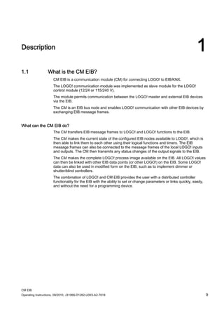
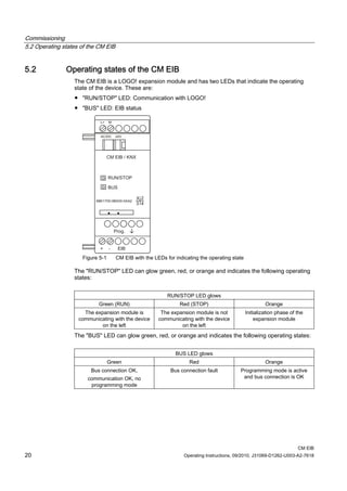
The CM EIB takes over communication between LOGO! and EIB and enables
communication via EIB inputs and outputs.
7.2 Communication with the LOGO! master
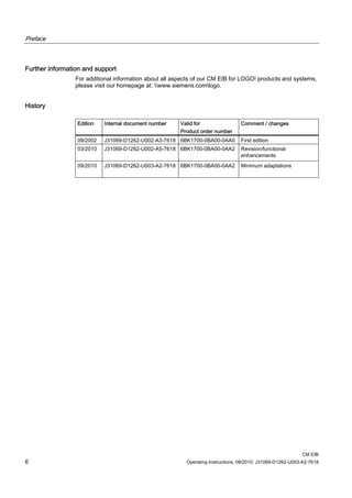
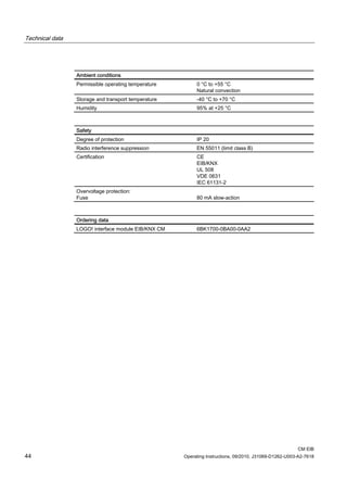
7.2.1 Process image
The process image is as follows.
Bit 7 Bit 6 Bit 5 Bit 4 Bit 3 Bit 2 Bit 1 Bit 0
Transfer_Buffer[0] I 8 I 7 I 6 I 5 I 4 I 3 I 2 I 1
Transfer_Buffer[1] I 16 I 15 I 14 I 13 I 12 I 11 I 10 I 9
Transfer_Buffer[2] I 24 I 23 I 22 I 21 I 20 I 19 I 18 I 17
Transfer_Buffer[3] Q8 Q7 Q6 Q5 Q4 Q3 Q2 Q1
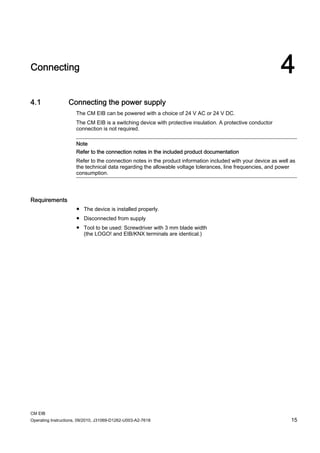
Transfer_Buffer[4] Q16 Q15 Q14 Q13 Q12 Q11 Q10 Q9
Transfer_Buffer[5]
Transfer_Buffer[6] Low Byte AI 1
Transfer_Buffer[7] High Byte AI 1
Transfer_Buffer[8] Low Byte AI 2
Transfer_Buffer[9] High Byte AI 2
Transfer_Buffer[10] Low Byte AI 3
Transfer_Buffer[11] High Byte AI 3
Transfer_Buffer[12] Low Byte AI 4
Transfer_Buffer[13] High Byte AI 4
Transfer_Buffer[14] Low Byte AI 5
Transfer_Buffer[15] High Byte AI 5
Transfer_Buffer[16] Low Byte AI 6
Transfer_Buffer[17] High Byte AI 6
Transfer_Buffer[18] Low Byte AI 7
Transfer_Buffer[19] High Byte AI 7
Transfer_Buffer[20] Low Byte AI 8
Transfer_Buffer[21] High Byte AI 8
Transfer_Buffer[22] Low Byte AQ 1
Transfer_Buffer[23] High Byte AQ 1
Transfer_Buffer[24] Low Byte AQ 2
Transfer_Buffer[25] High Byte AQ 2](https://image.slidesharecdn.com/lne0giqdsfe5ozznoyjy-signature-8cf552cbae5741209e73d76315d6227712e4af3c534b4de5ef70d54611ba47f4-poli-150402172613-conversion-gate01/85/Cm-eib-manual_201009_en-25-320.jpg)

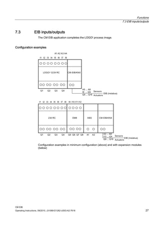
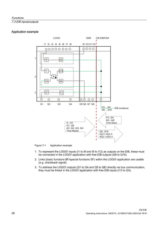
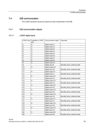
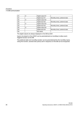
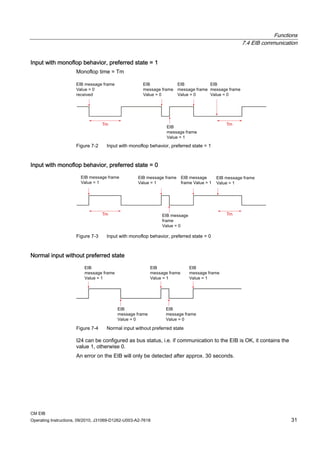


The document provides information about connecting Siemens' CM EIB communication module to both a LOGO! controller and an EIB/KNX building automation network. It describes how to install and connect the power supply and EIB bus, and outlines the commissioning process which involves programming the physical address via ETS software. The CM EIB makes the complete LOGO! process image and functions available via EIB communication objects and allows parameterization of analog/digital inputs and outputs. It can be used to implement distributed control functionality with the ability to quickly change parameters or links.