Strategies for Unlocking Knowledge Management in Microsoft 365 in the Copilot...
How does a servo motor work?
1. How does a servo motor work?
The simplicity of a servo is among the features that make them so reliable. The heart of a servo is a small
direct current (DC) motor, similar to what you might find in an inexpensive toy. These motors run on
electricity from a battery and spin at high RPM (rotations per minute) but put out very low torque (a
twisting force used to do work— you apply torque when you open a jar). An arrangement of gears takes
the high speed of the motor and slows it down while at the same time increasing the torque. (Basic law of
physics: work = force x distance.) A tiny electric motor does not have much torque, but it can spin really
fast (small force, big distance). The gear design inside the servo case converts the output to a much
slower rotation speed but with more torque (big force, little distance). The amount of actual work is the
same, just more useful. Gears in an inexpensive servo motor are generally made of plastic to keep it
lighter and less costly (see Figure 3 below). On a servo designed to provide more torque for heavier work,
the gears are made of metal (see Figure 4 below) and are harder to damage.
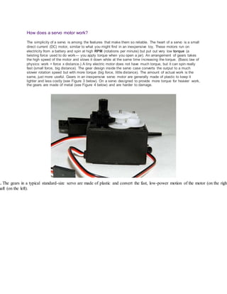
3. The gears in a typical standard-size servo are made of plastic and convert the fast, low-power motion of the motor (on the right
haft (on the left).
2. 4. In a high-power servo, the plastic gears are replaced by metal ones for strength. The motor is usually more powerful than in a l
d the overall output torque can be as much as 20 times higher than a cheaper plastic one. Better quality is more expensive, and h
ervos can cost two or three times as much as standard ones.
With a small DC motor, you apply power from a battery, and the motor spins. Unlike a simple DC motor,
however, a servo's spinning motor shaft is slowed way down with gears. A positional sensor on the final
gear is connected to a small circuit board (see Figure 5 below). The sensor tells this circuit board how far
the servo output shaft has rotated. The electronic input signal from the computer or the radio in a remote-
controlled vehicle also feeds into that circuit board. The electronics on the circuit board decode the
signals to determine how far the user wants the servo to rotate. It then compares the desired position to
the actual position and decides which direction to rotate the shaft so it gets to the desired position.
3. 5. The circuit board and DC motor in a high-power servo. Did you notice how few parts are on the circuit board? Servos have ev
fficient design over many years.
Imagine you are playing catch with a friend on a sports field. You stand at one end and want your friend
to go out for a long throw. You could keep calling out "farther, farther, farther" until she got as far away as
you wanted. But if she went out farther than you can throw, you would have to call out "closer" until she
got back to the right spot. If she were a simple motor in a robot arm and you were the microprocessor,
you would have to spend some of your time watching what she did and giving her commands to move her
back to the right spot (this is called a feedback loop). If she were a servo motor, you could just say "go
out exactly 4.5 meters" and know that she would find the right spot. That is what makes servo motors so
useful: once you tell them what you want done, they do the job without your help. This automatic seeking
behavior of servo motors makes them perfect for many robotic applications.
Types of servo motors
Servos come in many sizes and in three basic types: positional rotation, continuous rotation, and linear.
Positional rotation servo: This is the most common type of servo motor. The output shaft
rotates in about half of a circle, or 180 degrees. It has physical stops placed in the gear
mechanism to prevent turning beyond these limits to protect the rotational sensor. These
common servos are found in radio-controlled cars and water- and aircraft, toys, robots, and many
other applications.
Continuous rotation servo: This is quite similar to the common positional rotation servo motor,
except it can turn in either direction indefinitely. The control signal, rather than setting the static
position of the servo, is interpreted as the direction and speed of rotation. The range of possible
commands causes the servo to rotate clockwise or counterclockwise as desired, at varying
speed, depending on the command signal. You might use a servo of this type on a radar dish if
you mounted one on a robot. Or you could use one as a drive motor on a mobile robot.
4. Linear servo: This is also like the positional rotation servo motor described above, but with
additional gears (usually a rack and pinion mechanism) to change the output from circular to
back-and-forth. These servos are not easy to find, but you can sometimes find them at hobby
stores where they are used as actuators in larger model airplanes.
Selecting a servo motor
When starting a project that uses servos, look at your application requirements. How fast must the servo
rotate from one position to another? How hard will it have to push or pull? Do I need a positional rotation,
continuous rotation, or linear servo? How much overshoot is allowable? The less you pay for the servo,
the less mechanical power it will have to muster and the less precision it will have in its movements. You
can pay a bit more and get one that moves quickly, but it may not have a lot of power. You can also buy
one that will pull or push large loads, but it may not move quickly or precisely. Manufacturers' websites
and online hobby guides will have a lot of this information you can use to compare models. You will also
find that hobby stores have a selection of servos and can usually help you decide which one is right for
your project and budget.
Controlling a servo motor
Servos take commands from a series of pulses sent from the computer or radio. A pulse is a transition
from low voltage to high voltage which stays high for a short time, and then returns to low. In battery
devices such as servos, "low" is considered to be ground or 0 volts and "high" is the battery voltage.
Servos tend to work in a range of 4.5 to 6 volts, so they are extremely hobbyist computer-friendly.
Have you ever picked up one end of a rope that was tied to a tree or held one end of a jump rope while a
friend held the other? Imagine that, while holding your end of the rope, you moved your arm up and down.
The rope would make a big hump that would travel from your end to the other. What you have done is
applied a pulse, and it traveled down the rope as a wave. As you raise your hand up and down, if you
keep your hand in the air longer, someone watching this experiment from the side would see that the
pulse in the rope would be longer or wider. If you bring your hand down sooner, the pulse is shorter or
more narrow. This is the pulse width. If you keep your end going up and down, making a whole bunch of
these pulses one after another, you have created a pulse train (see Figure 6 below). How often did you
raise and lower your end? This is the frequency of your pulse train and is measured in pulses per
second, or Hz (abbreviation of "hertz").
Note: The microprocessor in your computer uses pulses from special clock circuitry to get the job done.
Have you heard of your computer speed referred to as something like 1.7 gigahertz (GHz)? This is a way
of saying that the pulses are coming at 1.7 billion pulses per second, or 1,700,000,000 Hz. Imagine trying
to move your rope that fast!
5. 6. An example of a pulse train you might generate to control a servo, as shown in a screen capture from an inexpensive
scilloscope, an instrument for observing voltages). Here, a pulse is generated once every 20 milliseconds, or at about 50 Hz. In t
the pulse width is about 2 milliseconds, which would have a servo rotate almost all the way to one end of its rotation. An oscillo
ibly useful for testing and debugging systems that use servos.
Your servo must be connected to a source of power (4.5 to 6 volts) and the control signal must come from
a computer or other circuitry. Each servo's requirements vary slightly, but a pulse train (as in Figure 6
above) of about 50 to 60 Hz works well for most models. The pulse width will vary from approximately 1
millisecond to 2 or 3 milliseconds (one millisecond is 1/1000 of a second). Popular hobbyist computers
such as the ArduinoTM have software commands in the language for generating these pulse trains. But
any microcontroller can be programmed to generate these waveforms. A system that passes information
based on the width of pulses uses pulse width modulation (or PWM) and is a very common way of
controlling motor speeds and LED brightness as well as servo motor position.
Resources
The following selection guide can help you determine which Futaba® servo fits your needs:
Hobbico, Inc. (2012). Futaba® servo selection. Retrieved September 13, 2012, from www.futaba-
rc.com/servos/servo-select.php
================================================================================
What are Servo Motors?
A servo motor is a linear or rotary actuator that provides fast precision position control
for closed-loop position control applications. Unlike large industrial motors, a servo
motor is not used for continuous energy conversion.
Servo motors have a high speed response due to low inertia and are designed with
small diameter and long rotor length. Then how do servo motors work?
6. Servo motors work on servo mechanism that uses position feedback to control the
speed and final position of the motor. Internally, a servo motor combines a motor,
feedback circuit, controller and other electronic circuit.
Servo motors
It uses encoder or speed sensor to provide speed feedback and position. This feedback
signal is compared with input command position (desired position of the motor
corresponding to a load), and produces the error signal (if there exist a difference
between them).
The error signal available at the output of error detector is not enough to drive the
motor. So the error detector followed by a servo amplifier raises the voltage and power
level of the error signal and then turns the shaft of the motor to desired position.
Types of Servo Motors
Basically, servo motors are classified into AC and DC servo motors depending upon the
nature of supply used for its operation. Brushed permanent magnet DC servo motors
are used for simple applications owing to their cost, efficiency and simplicity.
These are best suited for smaller applications. With the advancement of microprocessor
and power transistor, AC servo motors are used more often due to their high accuracy
control.
7. DC Servo Motors
A DC servo motor consists of a small DC motor, feedback potentiometer, gearbox,
motor drive electronic circuit and electronic feedback control loop. It is more or less
similar to the normal DC motor.
The stator of the motor consists of a cylindrical frame and the magnet is attached to the
inside of the frame.
DC Servo Motor
The rotor consists of brush and shaft. A commutator and a rotor metal supporting frame
are attached to the outside of the shaft and the armature winding is coiled in the rotor
metal supporting frame.
A brush is built with an armature coil that supplies the current to the commutator. At the
back of the shaft, a detector is built into the rotor in order to detect the rotation speed.
With this construction, it is simple to design a controller using simple circuitry because
the torque is proportional to the amount of current flow through the armature.
And also the instantaneous polarity of the control voltage decides the direction of torque
developed by the motor. Types of DC servo motors include series motors, shunt control
motor, split series motor, and permanent magnet shunt motor.
8. Working Principle of DC Servo Motor
A DC servo motor is an assembly of four major components, namely a DC motor, a
position sensing device, a gear assembly, and a control circuit. The below figure shows
the parts that consisting in RC servo motors in which small DC motor is employed for
driving the loads at precise speed and position.
Internal diagram
A DC reference voltage is set to the value corresponding to the desired output. This
voltage can be applied by using another potentiometer, control pulse width to voltage
converter, or through timers depending on the control circuitry.
The dial on the potentiometer produces a corresponding voltage which is then applied
as one of the inputs to error amplifier.
In some circuits, a control pulse is used to produce DC reference voltage corresponding
to desired position or speed of the motor and it is applied to a pulse width to voltage
converter.
In this converter, the capacitor starts charging at a constant rate when the pulse high.
Then the charge on the capacitor is fed to the buffer amplifier when the pulse is low and
this charge is further applied to the error amplifier.
9. So the length of the pulse decides the voltage applied at the error amplifier as a desired
voltage to produce the desired speed or position.
In digital control, microprocessor or microcontroller are used for generating the PWM
pluses in terms of duty cycles to produce more accurate control signals.
The feedback signal corresponding to the present position of the load is obtained by
using a position sensor. This sensor is normally a potentiometer that produces the
voltage corresponding to the absolute angle of the motor shaft through gear
mechanism. Then the feedback voltage value is applied at the input of error amplifier
(comparator).
The error amplifier is a negative feedback amplifier and it reduces the difference
between its inputs. It compares the voltage related to current position of the motor
(obtained by potentiometer) with desired voltage related to desired position of the motor
(obtained by pulse width to voltage converter), and produces the error either a positive
or negative voltage.
This error voltage is applied to the armature of the motor. If the error is more, the more
output is applied to the motor armature.
As long as error exists, the amplifier amplifies the error voltage and correspondingly
powers the armature. The motor rotates till the error becomes zero. If the error is
negative, the armature voltage reverses and hence the armature rotates in the opposite
direction.
Difference between the DC and AC Servo Motors
10. DC SERVO MOTOR AC SERVO MOTOR
It delivers high power output Delivers low output of about 0.5 W to 100 W
It has more stability problems It has less stable problems
It requires frequent maintenance due to
the presence of commutator
It requires less maintenance due to the absence of
commutator
It provides high efficiency The efficiency of AC servo motor is less and is about 5 to
20%
The life of DC servo motor depends on
the life on brush life
The life of AC servo motor depends on bearing life
It includes permanent magnet in its
construction
The synchronous type AC servo motor uses permanent
magnet while induction type doesn’t require it.
These motors are used for high power
applications
These motors are used for low power applications
==============================================================================
11. How servo motors work?
What is a servo?
A servo is a small motor that you can position at any angle very accurately. It contains
internal circuits that will automatically maintain that particular angle. However, you cannot
do full revolutions with a servo. You are restricted to a certain range, usually from 180-270
degrees. Servos are very powerful for their sizes. There exist servos that provide a torque
of 4kg-cm from a 50 gram servo!
Servos are often used in small sized humanoid robots (not Asimo). Space is a constraint,
but you need a lot of power to move without increasing the weight.
Positioning a servo
A servo has three wires. Two are for power (usually coloured black or brown for ground
and red for the positive terminal). The third wire is for signals to position the servo.
The signal wire expects input from a pulse width modulator. The period should be 20
milliseconds long and the duty cycle "encodes" the position of the motor.
If the duty cycle is 1 millisecond, the servo is positioned at 0 degrees. If the duty cycle is 2
milliseconds, the servo is positioned at the maximum possible angle (180 degrees, 270
degrees, or whatever is the maximum limit).
Positioning the servo
12. Internals of a servo
A servo contains a normal DC motor. This motor is connected to a potentiometer (or a
variable resistance) through gears. As the motor rotates, the potentiometer's resistance
changes. So the circuit can measure exactly what direction the motor's shaft is pointing.
When the shaft of the motor is at the desired position, power supply to the motor is
stopped. If not, the motor is turned in the appropriate direction.
The desired position is sent in through the signal wire. As long as the signal wire has a
position, the servo will ensure that the motor's shaft remains at the correct position.
Also, the speed with which the motor turns is proportional to the difference between its
actual position and desired position. So if the motor is near the desired position, it will turn
slow. Otherwise it will turn fast. This is called proportional control.
The internal components of a servo
Now for the electronics part. The circuit contains a chip, M51660L (or another proprietary
chip of the manufacturer). This chip compares the error in positioning the motor.
The chip contains a timer that produces pulse signals from the potentiometer. These signals
are similar to the ones you supply. These two pulse signals (the ones you are sending and
the ones generated by the potentiometer) are fed into a pulse width comparator. This
comparator produces the signals indicating which direction the motor should turn in. These
are fed into an H-bridge (a big H Bridge - L293D) to drive the motor.
All of this is contained within the chip. Only a few extra components like resistors and
capacitors are required.
13. The servo control circuit
Summary
You learned about how to control a servo motor and how its internal circuit works. You
even got to know how to start building your own controller if you ever wanted to.
- See more at: http://aishack.in/tutorials/servo-motors/#sthash.LUwYw4pr.dpuf
=================================================
TYPES OF MOTORS
SERVOCONTROL FACTSA HANDBOOKEXPLAININGTHE BASICSOFMOTION BALDOR ELECTRIC
COMPANYMN1205 TABLE OF CONTENTSTYPES OF MOTORS . . . . . . . . . . . . . . 3 OPEN LOOP/CLOSED
LOOP. . . . . 9 WHAT ISA SERVO. . . . . . . . . . . . . . 11 COMPENSATION .. . . . . . . . . . . . . . 13 TYPES OF
CONTROLS. . . . . . . . . . . 15 TYPES OFFEEDBACK DEVICES. 17 TYPES OF ACTUATORS. . . . . . . . . . 22 Page
2 Page 3 ServoControl FactsTYPES OF MOTORS The directcurrent(DC) motor isone of the first
machinesdevisedtoconvertelectrical energytomechanical power.Itsorigincanbe traced to machines
conceivedandtestedbyMichael Faraday,the experimenterwhoformulatedthe fundamental concepts
14. of electromagnetism.Theseconceptsbasicallystate thatif a conductor,or wire,carryingcurrentis
placedina magneticfield,aforce will actuponit.The magnitude of thisforce isa functionof strengthof
the magneticfield,the amountof currentpassingthroughthe conductorandthe orientationof the
magnetand conductor.The directioninwhichthisforce will actisdependentonthe directionof current
and directionof the magneticfield.Electricmotordesignisbasedonthe placementof conductors
(wires) inamagneticfield.A windinghasmanyconductors,orturns of wire,andthe contributionof
each individual turnaddstothe intensityof the interaction.The force developedfromawindingis
dependentonthe currentpassingthroughthe windingandthe magneticfieldstrength.If more current
ispassedthroughthe winding,thenmore force (torque) isobtained.Ineffect,twomagneticfields
interactingcause movement:the magneticfieldfromthe rotorandthe magneticfieldfromthe stators
attract each other.Thisbecomesthe basisof bothAC and DC motordesign.ACMOTORS Most of the
world'smotorbusinessisaddressedbyACmotors.ACmotorsare relativelyconstantspeeddevices.The
speedof an ACmotor isdeterminedbythe frequencyof the voltage applied(andthe numberof
magneticpoles).There are basicallytwotypesof ACmotors:inductionandsynchronous.INDUCTION
MOTOR. If the inductionmotorisviewedasatype of transformer,itbecomesMAGNETICFIELD
CURRENT FORCE Fig.1 - CONCEPTOFELECTROMAGNETISM ROTOR FIELD STATORFIELD INDUCED
VOLTAGE ANDCURRENT Fig.2 - INDUCTION MOTOR INDUCED V I Page 4 ServoControl Facts easyto
understand.Byapplyingavoltage ontothe primaryof the transformerwinding,acurrentflow results
and inducescurrentinthe secondarywinding.The primaryisthe statorassemblyandthe secondaryis
the rotor assembly.One magneticfieldissetupinthe statorand a secondmagneticfieldisinducedin
the rotor. The interactionof these twomagneticfieldsresultsinmotion.The speedof the magneticfield
goingaroundthe statorwill determine the speedof the rotor.The rotor will tryto follow the stator's
magneticfield,butwill"slip"whenaloadisattached.Therefore inductionmotorsalwaysrotate slower
than the stator's rotatingfield.Typical constructionof aninductionmotorconsistsof 1) a statorwith
laminationsandturnsof copperwire and2) a rotor,constructedof steel laminationswithlarge slotson
the periphery,stackedtogethertoforma "squirrel cage"rotor.Rotor slotsare filledwithconductive
material (copperoraluminum) andare short-circuiteduponthemselvesbythe conductiveendpieces.
This"one"piece castingusuallyincludesintegral fanbladestocirculate airfor coolingpurposes.The
standardinductionmotorisoperatedata "constant"speedfromstandardline frequencies.Recently,
withthe increasingdemandforadjustablespeedproducts,controlshave beendevelopedwhichadjust
operatingspeedof inductionmotors.Microprocessordrive technologyusingmethodssuchasvectoror
phase angle control (i.e.variablevoltage,variable frequency) manipulatesthe magnitude of the
magneticflux of the fieldsandthuscontrolsmotorspeed.Bythe additionof anappropriate feedback
sensor,thisbecomesaviable considerationforsome positioningapplications.Controllingthe induction
motor's speed/torque becomescomplex since motortorque isnolongerasimple functionof motor
current.Motor torque affectsthe slipfrequency,andspeedisafunctionof bothstator fieldfrequency
and slipfrequency.Inductionmotoradvantagesinclude:Low initial costdue tosimplicityinmotor
designandconstruction;availabilityof manystandardsizes;reliability;andquiet,vibration-free
operation.Forveryrapidstart-stoppositioningapplications,alargermotorwouldbe usedtokeep
temperaturesFig.3- CUTAWAY OFINDUCTION MOTOR STATORLAMINATIONSSTATORWINDINGS
SQUIRREL CAGE ROTOR FAN BLADES SHAFT HOUSINGPage 5 ServoControl Facts withindesignlimits.A
lowtorque to inertiaratiolimitsthismotortype tolessdemandingincrementing(start-stop)
applications.SYNCHRONOUSMOTOR.The synchronousmotorisbasicallythe same asthe induction
motor butwithslightlydifferentrotorconstruction.The rotorconstructionenablesthistype of motorto
15. rotate at the same speed(insynchronization) asthe statorfield.There are basicallytwotypesof
synchronousmotors:self excited( asthe inductionmotor) anddirectlyexcited (aswithpermanent
magnets).The self excitedmotor(maybe calledreluctancesynchronous) includesarotor withnotches,
or teeth,onthe periphery.The numberof notchescorrespondstothe numberof polesinthe stator.
Oftentimesthe notchesorteethare termedsalientpoles.Thesesalientpolescreate aneasypathfor
the magneticflux field,thusallowingthe rotorto"lockin"and run at the same speedasthe rotating
field.A directlyexcitedmotor(maybe calledhysteresissynchronous,orACpermanentmagnet
synchronous) includesarotorwitha cylinderof a permanentmagnetalloy.The permanentmagnet
north andsouthpoles,ineffect,are the salientteethof thisdesign,andtherefore preventslip.Inboth
the self excitedanddirectlyexcitedtypesthereisa"coupling"angle,i.e.the rotorlagsa small distance
behindthe statorfield.Thisangle will increase withload,andif the loadisincreasedbeyondthe motor's
capability,the rotorwill pull outof synchronism.The synchronousmotorisgenerallyoperatedinan
"openloop"configurationandwithinthe limiFig.4- CUTAWAY OF ACSYNCHRONOUSMOTOR STATOR
SHAFT ROTORSTATOR LAMINATIONSSTATORWINDINGSROTORWITH TEETH OR NOTCHES HOUSING
SHAFT Page 6 ServoControl Facts SHUNT WOUND MOTORS. Withthe shuntwound,the rotorand stator
(or fieldwindings) are connectedinparallel.The fieldwindingscanbe connectedtothe same power
supplyasthe rotor,or excitedseparately.Separateexcitationisusedtochange motorspeed(i.e.rotor
voltage isvariedwhile statororfieldwindingisheldconstant).The parallel connectionprovidesa
relative flatspeed-torque curve andgoodspeedregulationoverwide loadranges.However,because of
demagnetizationeffects,these motorsprovide startingtorquescomparativelylowerthanotherDC
windingtypes.SERIESWOUNDMOTORS. Inthe serieswoundmotor,the twomotorfieldsare connected
inseries.The resultistwostrongfieldswhichwillproduce veryhighstartingtorque.The fieldwinding
carriesthe full rotor current.These motorsare usuallyemployedwhere large startingtorquesare
requiredsuchascranes and hoists.Seriesmotorsshouldbe avoidedinapplicationstationsof the
couplingangle (or"pull-out"torque) itwill provide absolute constantspeedforagivenload.Also,note
that thiscategoryof motoris notself startingandemploysstartwindings(split-phase,capacitorstart),
or controlswhichslowlyrampupfrequency/voltageinordertostart rotation.A synchronousmotorcan
be usedin a speedcontrol systemeventhoughafeedbackdevice mustbe added.Vectorcontrol
approacheswill workquite adequatelywiththismotordesign.However,ingeneral,the rotorislarger
than that of an equivalentservomotorand,therefore,maynotprovide adequateresponse for
incrementingapplications.Otherdisadvantagesare:While the synchronousmotormaystarta high
inertial load,itmaynotbe able toaccelerate the loadenoughtopull itintosynchronism.If thisoccurs,
the synchronousmotoroperatesatlowfrequencyandat veryirregularspeeds,resultinginaudible
noise.Alsofora givenhorsepower,synchronousmotorsare largerandmore expensive thannon-
synchronousmotors.DCMOTORS Most of the world'sadjustable speedbusinessisaddressedby DC
motors.DC motor speedscaneasilybe varied,thereforetheyare utilizedinapplicationswhere speed
control,servocontrol,and/orpositioningneedsexist.The statorfieldisproducedbyeitherafield
winding,orbypermanentmagnets.Thisisastationaryfield(asopposedtothe ACstatorfieldwhichis
rotating).The secondfield,the rotorfield,issetupbypassingcurrentthrougha commutator andinto
the rotor assembly.The rotorfieldrotatesinanefforttoalignitself withthe statorfield,butatthe
appropriate time (due tothe commutator) the rotorfieldisswitched.Inthismethodthen,the rotor
fieldnevercatchesupto the stator field.Rotationalspeed(i.e.how fastthe rotorturns) is dependenton
the strengthof the rotor field. Inotherwords,the more voltage onthe motor,the fasterthe rotor will
turn.The followingwillbrieflyexplore the variouswoundfieldmotorsandthe permanentmagnet
16. (PMDC) motors.% RATED SPEED % RATED TORQUE 100 100 EMF SHUNT FIELD Fig.5 - TYPICALSPEED-
TORQUE CURVE FORSHUNT WOUND MOTORS Page 7 ServoControl FactsCOMPOUND WOUND
MOTOR. Compoundmotorsuse botha seriesanda shuntstator field.Manyspeedtorque curvescanbe
createdby varyingthe ratioof seriesandshuntfields.Ingeneral,smallcompoundmotorshave astrong
shuntfieldanda weakseriesfieldtohelpstartthe motor.Highstartingtorquesare exhibitedalongwith
relativelyflatspeedtorquecharacteristics.Inreversingapplications,the polarityof bothwindingsmust
be switched,thusrequiringlarge,complex circuits.where theyare likelytolose loadbecause of the
tendencyto"run away"underno-loadconditions.SERIESEMF Fig.6 TYPICAL SPEED-TORQUE CURVE
FOR SERIES WOUND MOTORS MOTORS % RATED SPEED % RATED TORQUE 100 200 STEPPERMOTOR.
Stepmotorsare electromechanical actuatorswhichconvertdigitalinputstoanalogmotion.Thisis
possible throughthe motor'scontrollerelectronics.There are varioustypesof stepmotorssuchas
solenoidactivated,variable reluctance,permanentmagnetandsynchronousinductor.Independentof
steppertype,all are deviceswhichindex infixedangularincrementswhenenergizedinaprogrammed
manner.Stepmotors'normal operationconsistsof discrete angularmotionsof uniformmagnitude
rather thancontinuousmotion.A stepmotorisparticularlywell suitedtoapplicationswhere the
controllersignalsappearaspulse trains.One pulse causesthe motortoincrementone angle of motion.
Thisis repeatedforone pulse.Moststepmotorsare usedinan openloopsystemconfiguration,which
can resultinoscillations.Toovercome this,eithercomplex circuitsorfeedbackisemployed –thus
resultinginaclosedloopsystem.Steppermotorsare,however,limitedtoaboutone horsepowerand
2000 rpm, therefore limitingtheminmanyapplications.DIGITALTRAIN OFPULSESROTATION Fig.8 -
STEPPER MOTOR % RATED SPEED % RATED TORQUE 100 100 SERIES EMF SHUNT FIELD Fig.7 TYPICAL
SPEED-TORQUE CURVE FOR COMPOUNDWOUND MOTORS Page 8 ServoControl Facts PMDC MOTOR.
The predominantmotorconfigurationutilizedindemandingincrementing(start-stop) applicationsisthe
permanentmagnetDC(PMDC) motor.This type withappropriate feedbackisquite aneffectivedevice in
closedloopservosystemapplications.Since the statorfieldisgeneratedbypermanentmagnets,no
powerisusedfor fieldgeneration.The magnetsprovideconstantfieldfluxatall speeds.Therefore,
linearspeedtorque curvesresult.Thismotortype providesrelativelyhighstarting,oracceleration
torque,islinearandpredictable,andhasasmallerframe andlighterweightcomparedtoothermotor
typesandprovidesrapidpositioning.HOUSINGBRUSHCOVERSPERMANENTMAGNETS ROTOR
COMMUTATOR MOUNTING BRUSHES Fig.9 - TYPICALDC MOTOR CONSTRUCTION Page 9 ServoControl
Facts OPEN LOOP/CLOSEDLOOP Ina system.the controlleristhe device whichactivatesmotionby
providingacommandto do something,i.e.startorchange speed/position.Thiscommandisamplified
and appliedontothe motor.Thusmotion commences... but how is thisknown?There are several
assumptionswhichhave beenmade.The firstassumptionisthatpowerisappliedontothe motorand
the secondisthat the motorshaftis free torotate.If there isnothingwrongwiththe system, the
assumptionsare fine –and indeedmotioncommencesandthe motorrotates.If forsome reason,either
the signal or powerdoesnotgetto the motor,or the motor issomehow preventedfromrotating,the
assumptionsare poorand there wouldbe nomotion.Systemsthatassume motionhastakenplace (oris
inthe processof takingplace) are termed"openloop".Anopenloopdrive isone inwhichthe signal
goes"inone directiononly"...from the control to the motor. There isno signal returningfromthe
motor/loadtoinformthe control that action/motionhasoccurred.A stepperdrive isaperfectexample
of an openloopsystem.One pulse fromthe control tothe motorwill move the motorone increment.If
for some reasonthe stepperdoesnotmove,forexample due tojamming,the control isunaware of the
problemandcannotmake any corrections.Asan example,suppose anapplicationcallsforautomatically
17. placingpartsintobinsA, B and C. The control can triggerone pulse,resultinginshaftrotationand
placementof apart inbinA. Twopulsescause shaftrotationandpart placementinbinB andthree
pulsesforpart placementinbinC.If for some reasonthe shaftcannot rotate to binsB and C, the control
isunaware of the problemandall parts are placed inbinA – a big problemif notdiscovered
immediatelybyanoperator.If a signal isreturnedtoprovide informationthatmotionhasoccurred,
thenthe systemisdescribedashavinga signal whichgoesin"twodirections":The commandsignal goes
out (tomove the motor),anda signal isreturned(the feedback) tothe control toinformthe control of
whathas occurred.The informationflowsback,orreturns.Thisisan example of a"closedloop"drive.
SIGNALGOES IN ONEDIRECTION MOTOR CONTROLFig.10 - OPEN LOOPDRIVE CONTROLBIN A BIN B
BIN C Fig.11 EXAMPLE OF AN APPLICATION USINGOPEN LOOPDRIVEMOTOR A SIGNALGOES OUT...
CONTROLMOTOR FEEDBACKDEVICE ...ANDA SIGNALRETURNS Fig.12 - CLOSED LOOP DRIVEPage 10
ServoControl Facts The returnsignal (feedbacksignal) providesthe meanstomonitorthe processfor
correctness.Fromthe automaticpickand place applicationexamplepreviouslycited,if the shaftcannot
rotate to binsB and C, the feedbackwill informthe control of anerror and the control can activate a
lightor a horn to alertthe operatorof the problem.Whenwouldanapplicationuse anopenloop
approach?First of all,justthinkof how simple itwouldbe tohookup – a few wiresandno adjustments.
Steppermotorsare traditionallyemployed inopenloopsystems... theyare easyto wire,theyinterface
easilywiththe user'sdigital computerandtheyprovide goodpositionrepeatability.Steppermotors,
however,are limitedtoapproximatelyone horsepower.Theirupperspeedlimitisabout2000 rpm. The
weaknessesof the openloopapproachinclude:Itisnotgoodfor applicationswithvaryingloads,itis
possible forasteppermotorto lose steps,itsenergyefficiencylevel islow andithasresonance areas
whichmustbe avoided.Whatapplicationsuse the closedlooptechnique?Those thatrequire control
overa varietyof complex motionprofiles.These mayinvolve the following:control of eithervelocity
and/orposition;highresolutionandaccuracy;velocitymaybe eitherveryslow,orveryhigh;andthe
applicationmaydemandhightorquesinasmall package size.Because of additionalcomponentssuchas
the feedbackdevice,complexityisconsideredbysome tobe a weaknessof the closedloopapproach.
These additional componentsdoaddto initial cost(anincrease inproductivityistypicallynot
consideredwheninvestigatingcost).Lackof understandingdoesgivethe impressiontothe userof
difficulty.Inmanyapplications,whetherthe openlooporclosedlooptechniquesemployedoftencomes
downto the basic decisionof the user.. . and the approach withwhichhe/she ismost
knowledgeable/comfortable with.Page 11 ServoControl FactsWHAT IS A SERVO?What isa servo?This
isnot easilydefinednorself-explanatorysince aservomechanism,orservodrive,doesnotapplytoany
particulardevice.Itisa termwhichappliestoa functionora task.The function,ortask,of a servocan
be describedasfollows.A commandsignal whichisissuedfromthe user'sinterface panelcomesinto
the servo's"positioningcontroller".The positioningcontrolleristhe devicewhichstoresinformation
aboutvariousjobsor tasks.It has beenprogrammedtoactivate the motor/load,i.e.change
speed/position.The signal thenpassesintothe servocontrol or "amplifier"section.The servocontrol
takesthislowpowerlevel signalandincreases,oramplifies,the poweruptoappropriate levelsto
actuallyresultinmovementof the servomotor/load.These low powerlevel signalsmustbe amplified:
Highervoltage levelsare neededtorotate the servomotorat appropriate higherspeedsandhigher
currentlevelsare requiredtoprovide torquetomove heavierloads.Thispowerissuppliedtothe servo
control (amplifier) fromthe "powersupply"whichsimplyconverts ACpowerintothe requiredDClevel.
It alsosuppliesanylowlevel voltagerequiredforoperationof integratedcircuits.Aspowerisapplied
ontothe servomotor,the loadbeginstomove . . . speedandpositionchanges.Asthe loadmoves,so
18. doessome other"device"move.Thisother"device"iseitheratachometer,resolverorencoder
(providingasignal whichis"sentback"to the controller).This"feedback"sigCOMMANDSIGNAL"AC"
POWER LOW LEVEL POWER HIGH LEVEL POWER SERVOMOTOR FEEDBACK LOAD SERVOCONTROL
(AMPLIFIER) PROGRAMMABLEPOSITIONINGCONTROLLERINTERFACEPANELPOWER SUPPLY "DC"
POWER Fig.13 - THE CONCEPTOFA SERVOSYSTEM Page 12 ServoControl Factsnal isinformingthe
positioningcontrollerwhetherthe motorisdoingthe properjob.The positioningcontrollerlooksatthis
feedbacksignal anddeterminesif the loadisbeingmovedproperlybythe servomotor;and,if not,then
the controllermakesappropriate corrections.Forexample,assumethe commandsignal wastodrive the
loadat 1000 rpm. For some reasonitis actuallyrotatingat 900 rpm. The feedbacksignal willinformthe
controllerthatthe speedis900 rpm. The controllerthencomparesthe commandsignal (desiredspeed)
of 1000 rpmand the feedbacksignal (actual speed) of 900 rpm and notesan error.The controllerthen
outputsa signal to applymore voltage ontothe servomotorto increase speeduntilthe feedbacksignal
equalsthe commandsignal,i.e.there isnoerror.Therefore,aservoinvolvesseveral devices.Itisa
systemof devicesforcontrollingsome item(load).The item(load) whichiscontrolled(regulated) canbe
controlledinanymanner,i.e.position,direction,speed.The speedorpositioniscontrolledinrelationto
a reference (commandsignal),aslongasthe properfeedbackdevice (errordetectiondevice) isused.
The feedbackandcommandsignalsare compared,andthe correctionsmade.Thus,the definitionof a
servosystemis,thatit consistsof several deviceswhichcontrol orregulate speed/positionof aload.
Page 13 ServoControl Facts COMPENSATION Whymustservosbe compensated?Simplystated,itis
requiredsothatthe controllerandmotor/loadi.e.machine will operateproperly.The machine must
produce accurate partsand have highproductivity.Inorder forthe machine to produce good,accurate
parts,it mustoperate intwo distinctmodes:transientandsteadystate.The firstmode of operation,the
transientstate (mayalsobe termeddynamicresponse state),occurswhenthe inputcommandchanges.
Thiscausesthe motor/loadtoaccelerate/decelerate i.e.change speed.Duringthistime period,there is
an associated1) time requiredforthe motor/loadtoreacha final speed/position(risetime) ,2) time
requiredforthe motor/loadtosettle and3) a certainamountof overshootwhichisacceptable.The
secondmode of operation,steadystate,occurswhenthe motor/loadhasreachedfinal speed,i.e.
continuousoperation.Duringthistime,there isanassociatedfollowingaccuracy(how accurate the
machine isperforming).Thisistypicallycalledsteadystate error.The machine mustbe capable of
operatinginthese twodistinctmodesinordertohandle the varietyof operationsrequiredformachine
performance.Andinorderthatthe machine will performwithout excessive overshoot,settlewithin
adequate time periods,andhave minimumsteadystate error,the servomustbe adjusted –or
compensated.Compensationinvolvesadjustmentortuningthe servo'sgainandbandwidth.Firstof all,
a lookat the definitionof thesetermsisinorderandthenhow theyaffectperformance.Gainisaratio
of outputversusinput.Asanexample,examine ahome stereosystem.The ratioof the inputsignal (as
receivedfromthe radiostation) versusthe outputsignal (whatyourearhears) isgain.If the volume
knobis low,the soundissoft – lowgain;if the volume isturneduphigh,the soundisloud – highgain.
Gain,therefore isameasure of the amplificationof the inputsignal.Inaservocontroller,gaineffects
the accuracy (i.e.howclose tothe desiredspeed,orpositionisthe motor'sactual speedorposition).
Highgain will allowsmall accurate movementandthe machine will be capable of producingprecise
parts. Bandwidthisexpressedormeasuredinfrequency.The home stereosystemwill againprovidean
example forthe definition.If the frequencyof the soundheardislow (base drum),there isnodifficulty
inhearingthe sound.Asthe frequencyisincreased,the listenerhasmore difficultyhearingthe sound.
At some point,the humanearcannot detectthe sound.Thisisattributedtothe range of frequencies
19. whichthe humanear can detect,i.e.the bandwidthtowhichthe humanearcan hear or respondto.In a
servo,bandwidthisameasure of howfastthe controller/motor/machinecanrespond.The widerthe
bandwidth,the fasterthe machine canrespond.Fastresponse will enablethe machine toreactrapidly,
producingmanyparts.FOLLOWING ACCURACYOR STEADY STATE ERROR RISE TIME SETTLE TIME
TRANSIENTSTATE STEADY STATE Fig.14 - SERVORESPONSEPage 14 ServoControl Facts Whythen,are
not all servosdesignedwithhighgain(highaccuracy) andwide bandwidth(fastresponse)?Thisis
attributedto1) limitationsof the componentsand2) resonantconditions.Limitsof the components–
theycan handle onlysomuch power.Inaddition,increasinggainaddscomponents,cost,complexity.
Resonantconditions –To explainthis,imagineayard stickheldinyourhand.Slowlymove itupand
down.. . note that the far endof the rodwill follow yourhandmovement.Asmovementisincreased
(increasingfrequencyof motion) the farendof the yard stickwill bendinitsattempttokeepupwith
your handmovements.Atsome frequencyitispossible tobreakthe stick.. . this isthe resonantpoint.
Justas withthisexample,all systemshave aresonantpoint,whetherthatsystemisabridge,a tank or a
servo.Machinesmustnot be operatedatthe resonantpointotherwise instabilityandsevere damage
will occur.In conclusion,servosare compensatedor"tuned"viaadjustmentsof gainandresponse so
that the machine will produce accurate partsat a highproductivityrate.Page 15 ServoControl Facts
TYPES OF CONTROLSThe control of a motor will employsometype of powersemiconductor.These
devicesregulate the amountof powerbeingappliedontothe motor,andmovingthe load.One type of
semiconductoristhe SCR(siliconcontrollerrectifier) whichwill be connectedtothe ACline voltage.This
type of device isusuallyemployedwhere large amountsof powermustbe regulated,motorinductance
isrelativelyhighandaccuracyinspeedisnot critical (suchas constantspeeddevicesforfans,blowers,
conveyorbelts).Poweroutof the SCR,whichis available torunthe motor,comesindiscrete pulses.At
lowspeedsacontinuousstreamof narrow pulsesisrequiredtomaintainspeed.If anincrease inspeed
isdesired,the SCRmustbe turnedon to applylarge pulsesof instantpower,andwhenlowerspeedsare
desired,powerisremovedandagradual coastingdownin speedoccurs.A good example wouldbe
whenone car is towingasecondcar. The driverinthe firstcar isthe SCRdevice andthe secondcar,
whichisbeingtowedisthe motor/load.Aslongasthe chain istaut, the driverinthe firstcar isin control
of the secondcar. But suppose the firstcar slowsdown.There wouldbe slackinthe chainand,at that
point,the firstcar is nolongerincontrol (and won'tbe until he getsintoa positionwherethe chainis
taut again).So,for the periodsof time whenthe firstcarmust slow down,the driverisnotincontrol.
Thissequence occursrepeatedly,resultinginajerky,coggingoperation.Thistype of speedcontrol is
adequate formanyapplicationsIf smootherspeedisdesired,anelectronic networkmaybe introduced.
By insertinga"lag"network,the response of the control isslowedsothata large instantpowerpulse
will notsuddenlybe applied.Filteringactionof the lagnetworkgivesthe motora sluggishresponsetoa
suddenchange inloador speedcommandchanges.Thissluggishresponse isnotimportantin
applicationswithsteadyloadsorextremelylarge inertia.Butforwide range,highperformancesystems,
inwhichrapidresponse isimportant,itbecomesextremelydesirable tominimizesluggishreactionsince
a rapid changestospeedcommandsare desirable.Transistorsmayalsobe employedtoregulate the
amountof powerappliedontoamotor.Withthisdevice,there are several "techniques",ordesign
methodology,usedtoturntransistors"on"and "off".The "technique"ormode of operationmaybe
"linear","pulse widthmodulated"(PWM) or"pulse frequencymodulated"(PFM).The "linear"mode
usestransistorswhichare activated,orturnedon,all the time supplyingthe appropriate amountof
powerrequired.Transistorsactlike awaterfaucet,regulatingthe appropriateamountof powertodrive
the motor.If the transistoristurnedon half way,thenhalf of the powergoestothe motor. If the
20. transistoristurnedfullyon,thenall of the powergoesto the motorand it operatesharder/faster.Thus
for the lineartype of control,powerisdeliveredconstantly,notindiscrete pulses(like the SCRcontrol).
Thus betterspeedstabilityandcontrol isobtained.Anothertechnique istermedpulse widthmodulation
(PWM).WithPWM techniques,powerisregulatedbyapplyingpulsesof variable width,i.e.bychanging
or modulatingthe pulse widthsof the power.Incomparisonwiththe SCRcontrol (whichapplieslarge
pulsesof power),the PWMAVAILABLEVOLTAGEPULSES OF POWER TO MOTOR MAINTAIN SPEED
INCREASESPEED SLOW DOWN Fig.15 - AN SCR CONTROLPage 16 ServoControl Facts technique applies
narrow,discrete (whennecessary) powerpulses.Operationisasfollows:Withthe pulse widthsmall,the
average voltage appliedontothe motorislow,andthe motor'sspeedisslow.If the widthiswide,the
average voltage ishigher,andthereforemotorspeedishigher.Thistechnique hasthe advantage inthat
the powerlossinthe transistoris small,i.e.the transistoriseitherfully"on"orfully"off"and,therefore,
the transistorhas reducedpowerdissipation.Thisapproachallowsforsmallerpackage sizes.The final
technique usedtoturntransistors"on"and"off"is termedpulse frequencymodulation(PFM).With
PFM, the powerisregulatedbyapplyingpulsesof variable frequency,i.e.bychangingormodulatingthe
timingof the pulses.The systemoperatesasfollows:Withveryfew pulses,the average voltage applied
ontothe motoris low,andmotor speedisslow.Withmanypulses,the average voltage isincreased,and
motor speedishigher.DRIVETYPESOPEN LOOP •SIGNALSTARTS MOTION •NO FEEDBACKSIGNAL
EXAMPLE: STEPPER CLOSED LOOP• SIGNALCOMMANDS MOTION •FEEDBACK SIGNALRETURNS
EXAMPLE: SERVOMOTOR+ FEEDBACKDEVICE TYPES OF CONTROLSACDC •CONVERTSACTO DC TO AC
EXAMPLE: VECTOR•CONVERTSAC TO DC EXAMPLE: DC SERVOOUTPUT POWERDEVICES SCR•LARGE
PULSES OF POWER EXAMPLE: SCR SPEED CONTROLTRANSISTOR•SMOOTH OPERATION EXAMPLE:
SERVOCONTROL TECHNIQUES TO TURN TRANSISTORSOFFANDON PULSE FREQUENCY MODULATION
(PFM) •TRANSISTOREITHER OFF OR ON •AMPLITUDE OF VOLTSCONSTANT•TURN ON TIME VARIED
•LOW POWERDISSIPATION PULSEWIDTH MODULATION (PWM) •TRANSISTOREITHER ON OR OFF
•AMPLITUDE OF VOLTSCONSTANT•WIDTH OF PULSE VARIED•LOW POWER DISSIPATION LINEAR
•TRANSISTORALWAYSON •AMPLITUDE OFVOLTS VARIED•HIGH INTERNALPOWERDISSIPATEDFig.18
- SUMMARY OF DRIVETYPES NARROWPULSE WIDE PULSE t1 t2 t1 t = 2 Fig.16 PULSE WIDTH
DETERMINES AVERAGE VOLTAGEAVG.VOLTS AVG.VOLTSAVG.VOLTS AVG.VOLTSt1 t = 2 = VARIABLE
FREQUENCY t1 t2 Fig.17 PULSE FREQUENCY MODULATION TO DETERMINE AVERAGEVOLTAGEPage 17
ServoControl Facts Servosuse feedbacksignalsforstabilization,speedandpositioninformation.This
informationmaycome froma varietyof devicessuchasthe analogtachometer,the digital tachometer
(optical encoder) orfroma resolver.Inthe following,eachof these deviceswill be definedandthe
basicsexplored.TYPESOFFEEDBACKDEVICESANALOGTACHOMETERS Tachometersresemble miniature
motors.However,the similarityceasesthere.Inatachometer,the gauge of wire isquite fine,thusthe
currenthandlingcapabilityissmall.Butthe tachometerisnotusedfora powerdeliveringdevice.
Instead,the shaftisturnedbysome mechanical meansanda voltage isdevelopedatthe terminals(a
motor inreverse!).The fasterthe shaftisturned,the largerthe magnitude of voltagedeveloped(i.e.the
amplitude of the tachsignal isdirectlyproportionaltospeed). The outputvoltageshowsapolarity(+or
-) whichisdependentondirectionof rotation.Analog,orDCtachometers,astheyare oftentermed,
playan importantrole indrives,because of theirabilitytoprovide directional androtational
information.Theycanbe usedtoprovide speedinformationtoameter(forvisual speedreadings) or
provide velocityfeedback(forstabilizationpurposes).The DCtach providesthe simplest,mostdirect
methodof accomplishingthisfeat.Asanexample of adrive utilizingananalogtach for velocity
information,consideraleadscrewassemblywhichmustmove aloadat a constantspeed.The motoris
21. requiredtorotate the leadscrewat 3600 rpm. If the tachometer'soutputvoltage gradientis2.5
volts/Krpm,the voltage readonthe tachometerterminalsshouldbe:3.600 Krpm x 2.5 volts/Krpm= 9
voltsIf the voltage readis indeed9volts,thenthe tachometer(andmotor/load) isrotatingat3600 rpm.
The servodrive will tryto maintainthisvoltage toassure the desiredspeed.Althoughthisexample has
beensimplified,the basicconceptof speedregulationviathe tachometerisillustrated.Some of the
terminologyassociatedwithtachometerswhichexplainsthe basiccharacteristicsof thisdevice are:
voltage constant,ripple andlinearity.The followingwill define each.A tachometer'svoltageconstant
may alsobe referredtoas voltage gradient,orsensitivity.Thisrepresentsthe outputvoltagegenerated
froma tachometerwhenoperatedat1000 rpm, i.e.V/Krpm.Sometimesconvertedandexpressedin
voltsperradianper second,i.e.V/rad/sec.Ripplemaybe termedvoltage ripple ortachometerripple.
Since tachs are not ideal devices,anddesignandmanufacturingtolerancesenterintothe product,there
are deviationsfromthe norm.Whenthe shaftisrotated,a DC signal isproducedaswell asa small
amountof an ACsignal + MECHANICALLY ROTATE OUTPUT VOLTSSPEED OUTPUT VOLTAGETACH
OUTPUT PROPORTIONALTOSPEEDFig. 19 - TACHOMETER Page 18 ServoControl Facts whichis
superimposeduponthe DClevel.Inreviewingliterature,care mustbe exercisedtodeterminethe
definitionof ripplesince there are three methodsof presentingthe data:1) Peak-to-peak–the ratioof
peak-to-peakrippleexpressedasapercentof the average DC level;2) RMS – the ratio of the RMS of the
AC componentexpressedasa percentof the average DC level and3) Peakto Average – the ratioof
maximumdeviationfromthe average DCvalue expressedasa percentof the average DC level.Linearity
– The ideal tachometerwouldhave aperfectstraightline forvoltagevs.speed.Again,designand
manufacturingtolerancesenterthe picture andalterthisstraightline.Thus,linearityisameasure of
howfar away fromperfectthisproductor designis.The maximumdifference of the actual versus
theoretical curvesislinearity(expressedinpercentage).RIPPLEDCVOLTS0 Fig.20 - TACH RIPPLE SCOPE
VOLTSVS. TIME TIME VOLTS ACTUAL IDEALSPEED VOLTS Fig.21 - TACH LINEARITYDIGITAL
TACHOMETERS A digital tachometer, oftentermedanoptical encoderorsimplyencoder,isa
mechanical-to-electrical conversiondevice.The encoder'sshaftisrotatedandan outputsignal results
whichisproportional todistance (i.e.angle) the shaftisrotatedthrough.The outputsignal maybe
square waves,orsinusoidal waves,orprovide anabsolute position.Thusencodersare classifiedinto
twobasic types:absolute andincremental.ABSOLUTEENCODER.The absolute encoderprovidesa
specificaddressforeachshaftpositionthroughout360degrees.Thistype of encoderemployseither
contact (brush) ornon-contactschemesof sensingposition.The contactscheme incorporatesabrush
assemblytomake directelectrical contactwiththe electricallyconductivepathsof the codeddiskto
readaddressinformation.The non-contactscheme utilizesphotoelectricdetectiontosense positionof
the codeddisk.The numberof tracks on the codeddiskmay be increaseduntil the desiredresolutionor
accuracy is achieved.Andsince positioninformationis directlyonthe codeddiskassembly,the diskhas
a Page 19 ServoControl Factsbuilt-in"memorysystem"andapowerfailure willnotcause this
informationtobe lost.Therefore,itwill notbe requiredtoreturntoa "home"or "start" positionupon
reenergizingpower.EXAMPLEBRUSH DISK Fig.22 - ABSOLUTE ENCODERINCREMENTAL ENCODER.The
incremental encoderprovideseitherpulsesora sinusoidaloutputsignal asitisrotatedthroughout360
degrees.Thusdistance dataisobtainedbycountingthisinformation.The diskismanufacturedwith
opaque lines.A lightsource passesabeamthroughthe transparentsegmentsontoaphotosensorwhich
outputsa sinusoidal waveform.Electronicprocessingcanbe usedto transformthissignal intoa square
pulse train.In utilizingthisdevice,the followingparametersare important:1) Line count:This isthe
numberof pulsesperrevolution.The numberof linesisdeterminedbythe positionalaccuracyrequired
22. inthe application.2) Outputsignal:The outputfromthe photosensorcanbe eitherasine or square
wave signal.3) Numberof channels:Eitherone ortwo channel outputscanbe provided.The two
channel versionprovidesLIGHTSOURCE DISKGRID ASSEMBLY PHOTOSENSORPICKUP SQUARING
CIRCUITRY Fig.23 - INCREMENTALENCODER Page 20 ServoControl Facts a signal relationshiptoobtain
motiondirection(i.e.clockwiseorcounterclockwise rotation).Inaddition,azeroindex pulse canbe
providedtoassistindeterminingthe "home"position.A typical applicationusinganincremental
encoderisas follows:Aninputsignal loadsacounterwithpositioninginformation.Thisrepresentsthe
positionthe loadmustbe movedto.Asthe motoraccelerates,the pulsesemittedfromthe incremental
(digital) encodercome atan increasing rate until aconstantrun speedisattained.Duringthe runperiod,
the pulsescome at a constantrate whichcan be directlyrelatedtomotorspeed.The counter,inthe
meanwhile,iscountingthe encoderpulsesand,ata predeterminedlocation,the motoriscommanded
to slowdown.Thisisto preventovershootingthe desiredposition.Whenthe counteriswithin1or 2
pulsesof the desiredposition,the motoriscommandedtostop.The load isnow in position.RESOLVERS.
Resolverslooksimilartosmall motors –that is,one endhasterminal wires,andthe otherendhasa
mountingflange andashaft extension.Internally,a"signal"windingrotorrevolvesinsideafixedstator.
Thisrepresentsatype of transformer:Whenone windingisexcitedwithasignal,throughtransformer
actionthe secondwindingisexcited.Asthe firstwindingismoved(the rotor),the outputof the second
windingchanges(the stator).Thischange isdirectlyproportional tothe angle whichthe rotorhasbeen
movedthrough.Asa startingpoint,the simplestresolverunitcontainsasingle windingonthe rotorand
twowindingsonthe stator (located90 degreesapart).A reference signal isappliedontothe primary
(the rotor),thenviatransformeractionthisiscoupledtothe secondary. The secondary'soutputsignal
wouldbe a sine wave proportional toangle VACVOUTFig.25 - RESOLVER: A ROTATINGTRANSFORMER
SPEED INPUT SIGNALUP/DOWN COUNTER SERVOCONTROL SERVOENCODER ENCODERPULSES Fig.24 -
EXAMPLE USING ENCODER PULSES MECHANICALREVOLUTION 360° MECHANICALREVOLUTION ROTOR
STATOR V1 OUT SINE Fig.26 - TYPICALRESOLVER OUTPUT V2 OUT COSINE360° Page 21 ServoControl
Facts (the otherwindingwouldbe acosine wave),withone electrical cycle of outputvoltage produced
for each360 degreesof mechanical rotation.These are fedintothe controller.Insidethe controller,a
resolvertodigital (RtoD) converteranalyzesthe signal,producinganoutputrepresentingthe angle
whichthe rotor has movedthrough,andan outputproportional tospeed(how fastthe rotorismoving).
There are varioustypesof resolvers.The type describedabove wouldbe termedasingle speedresolver;
that is,the outputsignal goesthroughonlyone sine wave asthe rotor goesthrough360 mechanical
degrees.If the outputsignal wentthroughfoursine wavesasthe rotorgoesthrough360 mechanical
degrees,itwouldbe calleda4 -speedresolver.Anotherversionutilizesthree windingsonthe stator –
and wouldbe calledasynchro.The three windingsare located120 degreesapart.The basic type of
resolverdiscussedthusfarmayalsobe termeda"resolvertransmitter" –one phase inputandtwo
phase outputs(i.e.asingle windingof the rotorisexcitedandthe stator'stwo windingsprovide position
information).Resolvermanufacturersmaytermthisa"CX" unit,or "RCS"unit.Anothertype of resolver
istermed"resolvercontrol transformer" –two phase inputsandone phase output(i.e.the twostator
windingsare excitedandthe rotorsingle windingprovidesposition information).Resolver
manufacturerstermthistype "CT"or "RCT" or "RT". The thirdtype of resolveristermeda"resolver
transmitter"– twophase inputsandtwo phase outputs(i.e.tworotorwindingsare excited,andposition
informationisderivedfromthe twostatorwindings).Thismaybe referredtoas "differential"resolver,
or "RD", or "RC" dependingonthe manufacturer.Page 22 ServoControl Facts The basicactuators for
controllingmotion(whichinvolvecontrol of eitherspeed,torqueorpositional accuracy) wouldinclude:
23. • AirMotors • HydraulicMotors• Clutch/Brake •StepperMotors • AC InductionMotors• Servomotors
The followingpresentsasynopsis,of the strengthsandweaknessesof eachbasicmotioncontrol
technique.AirMotors – use compressedairtocreate motion.Pressure andflow determine speedand
torque positional accuracyisusuallynota requirement.Principle strengths:1.Low cost 2. Available
components3.Easy to apply4. Easy to maintain5 .Easy to understand6.Centralized powersource
Hydraulicmotors – use pressurizedoil tomove apiston.Higherpressure resultsinhighertorque (i.e.
brute force).Principlestrengths:1.Easy to apply2. High torquesavailable3.Centralizedpowersource
4. Easy to understandClutch/Brake –a device couplingacontinuouslyrotatingshaftandaload.
Uncouplingthe loadresultsinstopping.Varyingon/off timeresultsinvaryingdistances.Principle
strengths:1. Easy to apply2. Low comparative cost3. Good forstart/stopwithlightloads 4. Easy to
provide speedmatchingPrinciple weaknesses:1.Audible compressornoise2.Difficulttoregulate speed
3 Prone tocontamination4.Energy inefficientTYPESOFACTUATORSPrinciple weaknesses:1.Audible
noise 2. Difficulttocontrol speed3.Slow positioning4.Prone to leaks5. Energyinefficient6.Fire hazard
7. High maintenance requiredPrinciple weaknesses:1.Uncontrolledacceleration2.Inaccurate 3. Prone
to wear4. Non-repeatableperformance SteppingMotors – electromechanical device whichconverts
one digital pulse intoaspecificrotational movementordisplacement.A "trainof pulses"resultsin
rotational speed.Principle strengths:1.Simple control 2.Moderate cost 3. Good for constantloads4.
Good positional accuracyACInduction Motors– widelyusedforconstantspeedrequirements.Electric
"starters"provide connections/start-up/overloadprotection.Newertechnologyprovidesvariable speed
capability.Principlestrengths:1.Simple motor2. Low cost 3. Mature technology4.Straightforward
on/off control 5. Affordablecoarse speedcontrol 6.Simple wiring7.Wide productvariety8. Many
vendorsavailableServomotors –A motorwitha "feedback"device.Electronicpackagescontrol speed
and positionaccuracy.Principle strengths:1. Highperformance 2.Small size 3.Wide varietyof
components4.High speedsavailable withspecializedcontrolsPage 23 ServoControl FactsPrinciple
weaknesses:1.Prone tolosingsteps2. Notgood forvaryingloads3. Energy inefficient4.Large motor
size 5. Resonance problemsPrinciple weaknesses:1.Limitedpositioncontrol 2.Relativelylargersize
Principle weaknesses:1.Slightlyhighercost2. Highperformance limitedbycontrols3.High speed
torque limitedbycommutatororelectronicsTYPESOFACTUATORS(cont.) BALDORELECTRIC COMPANY
5711 South7th StreetFortSmith,Arkansas72901 (501) 646-4711 Fax (501) 648-5792 `3/94 5M CMc