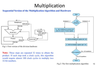
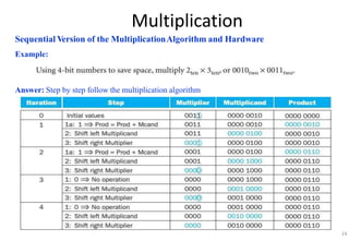
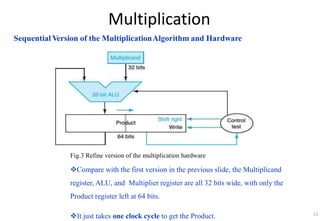
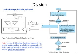
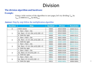
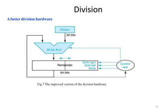
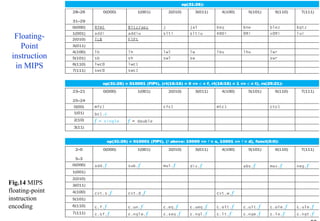
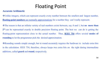
1
• CHAPTER 3
• ARITHMETIC FOR COMPUTERS
COMPUTER ARCHITECTURE
2
Arithmetic for
Computers
1. Introduction
2. Addition and Subtraction
3. Multiplication
4. Division
5. Floating Point
6. Parallelism and Computer Arithmetic: Associativity
Arithmetic for Computers
3
4
Arithmetic for Computers
1. Introduction
2. Addition and Subtraction
3. Multiplication
4. Division
5. Floating Point
6. Parallelism and Computer Arithmetic: Associativity
5
Introduction
Computer words are composed of bits; thus, words can be represented as binary
numbers. Chapter 2 shows that integers can be represented either in decimal or
binary form, but what about the other numbers that commonly occur?
For example:
■ What about fractions and other real numbers?
■ What happens if an operation creates a number bigger than can be
represented?
■ And underlying these questions is a mystery:How
does hardware
really multiply or divide numbers?
6
Arithmetic for Computers
1. Introduction
2. Addition and Subtraction
3. Multiplication
4. Division
5. Floating Point
6. Parallelism and Computer Arithmetic: Associativity
Addition and Subtraction
Addition:
Binary addition, showing carries from right to left
7
Addition and Subtraction
Subtraction:
8
Addition and Subtraction
Overflow
When does the overflow occur on the signed number?
We also need to conrn:
-How to detect overflow for two’s complement numbers in a computer?
-What about overflow with unsigned integers? (Unsigned integers are commonly
used for memory addresses where overflows are ignored.)
9
10
Addition and Subtraction
Overflow
The computer designer must therefore provide a way to ignore overflow in some cases and to
recognize it in others.
The MIPS solution is to have two kinds of arithmetic instructions to recognize the two
chois:
■ Add (add), add immediate (addi), and subtract (sub) cause exptions (interrupt) on
overflow.
■ Add unsigned (addu), add immediate unsigned (addiu), and subtract unsigned
(subu) do not cause exptions on overflow.
Note: MIPS detects overflow with an exption, also called an interrupt on many computers.
An exption or interrupt is essentially an unscheduled produre call.
11
Arithmetic for Computers
1. Introduction
2. Addition and Subtraction
3. Multiplication
4. Division
5. Floating Point
6. Parallelism and Computer Arithmetic: Associativity
Multiplication
Although the decimal example above happens to use only 0 and 1, multiplication of
binary numbers must always use 0 and 1, and thus always offers only these two chois:
1. Just pla a copy of the multiplicand (1 ×multiplicand) in the proper pla if the
multiplier digit is a 1.
2. Pla 0 (0 ×multiplicand) in the proper pla if the multiplier digit is 0.
Example
12
Multiplication
13
Sequential Version of the MultiplicationAlgorithm and Hardware
Fig.1: First version of the division hardware
Note: Three steps are repeated 32 times to obtain the
product. If each step took a clock cycle, this algorithm
would require almost 100 clock cycles to multiply two
32-bit numbers.
Fig.2: The first multiplication algorithm
Multiplication
Sequential Version of the MultiplicationAlgorithm and Hardware
Example:
Answer: Step by step follow the multiplication algorithm
14
Multiplication
Sequential Version of the MultiplicationAlgorithm and Hardware
Fig.3 Refine version of the multiplication hardware
Compare with the first version in the previous slide, the Multiplicand
register, ALU, and Multiplier register are all 32 bits wide, with only the
Product register left at 64 bits.
It just takes one clock cycle to get the Product. 15
16
Multiplication
Signed Multiplication
The easiest way to understand how to deal with signed numbers is to first convert
the multiplier and multiplicand to positive numbers and then remember the
original signs.
The algorithms should then be run for 31 iterations, leaving the signs out of
the calculation.
It turns out that the last algorithm will work for signed numbers.
Multiplication
Faster Multiplication
Fig.4 Fast multiplication hardware.
17
18
Multiplication
Multiply in MIPS
MIPS provides a separate pair of 32-bit registers to contain the 64-bit product, called Hi
and Lo.
To produ a properly signed or unsigned product, MIPS has two instructions: multiply (mult)
and multiply unsigned (multu).
To fetch the integer 32-bit product, the programmer uses move from lo (mflo). The MIPS
assembler generates a pseudo instruction for multiply that specifies three general purpose
registers, generating mflo and mfhi instructions to pla the product into registers.
19
Arithmetic for Computers
1. Introduction
2. Addition and Subtraction
3. Multiplication
4. Division
5. Floating Point
6. Parallelism and Computer Arithmetic: Associativity
Division
 The reciprocal operation of multiply is divide, an operation that is even less
frequent and even more quirky.
 It even offers the opportunity to perform a mathematically invalid operation:
dividing by 0.
Example:
20
Division
21
Adivision algorithm and hardware
Fig.5 First version of the multiplication hardware
Note: both the dividend and the divisor are positive and
hen the quotient and the remainder are nonnegative. The
division operands and both results are 32-bit values, and
we will ignore the sign for now.
Fig.6 The first division algorithm
Division
The division algorithm and hardware
Example:
Answer: Step by step follow the multiplication algorithm
22
Division
Afaster division hardware
Fig.7 The improved version of the division hardware
23
Division
Signed division
The simplest solution is to remember the signs of the divisor and dividend and then negate
the quotient if the signs disagree.
The one complication of signed division is that we must also set the sign of the remainder.
Remember that the following equation must always hold:
Dividend = Quotient x Divisor + Remainder
 Remainder = Dividend – (Quotient x Divisor)
Example:
24
25
Division
Divide in MIPS
You may have already observed that the same sequential hardware can be used for both
multiply and divide in Fig.3 and Fig.7 .
The only requirement is a 64-bit register that can shift left or right and a 32-bit ALU that
adds or subtracts. Hen, MIPS uses the 32-bit Hi and 32-bit Lo registers for both multiply and
divide.
As we might expect from the algorithm above, Hi contains the remainder, and Lo contains
the quotient after the divide instruction completes.
To handle both signed integers and unsigned integers, MIPS has two instructions: divide
(div) and divide unsigned (divu).
The MIPS assembler allows divide instructions to specify three registers, generating
the mflo or mfhi instructions to pla the desired result into a general-purpose register.
26
Arithmetic for Computers
1. Introduction
2. Addition and Subtraction
3. Multiplication
4. Division
5. Floating Point
6. Parallelism and Computer Arithmetic: Associativity
Floating Point
Definitions
Some representations of the real number:
27
 The alternative notation for the above last two numbers is called scientific
notation, which has a single digit to the left of the decimal point.
 A number in scientific notation that has no leading 0s is called a normalized number
Example: 1.0ten x 10-9: normalized scientific number
0.1ten x 10-8: not normalized scientific number 10.0ten x 10-10: not normalized scientific number
 The binary number shown in scientific notation is called floating point
Floating point: Computer arithmetic that represents numbers in which the binary point is not
fixed.
Floating Point
Floating-Point representation
A designer of a floating-point representation must find a compromise between the size of the
fraction and the size of the exponent.
This tradeoff is between precision and range:
- Increasing the size of the fraction enhans the precision of the fraction.
- Increasing the size of the exponent increases the
range of numbers that can be represented.
Floating-point numbers are usually a multiple of the size of a word. The representation of a
MIPS floating-point number:
28
Where
s is the sign of the floating-point number (1 meaning negative)
exponent is the value of the 8-bit exponent field (including the sign of the exponent)
fraction is the 23-bit number
This representation is called sign and magnitude, sin the sign is a separate bit from the rest of the
number.
In general, floating-point numbers are of the form:
Floating Point
Floating-Point representation
Overflow (floating-point): A situation in which a positive exponent becomes too large to fit in
the exponent field.
Underflow (floating-point): A situation in which a negative exponent becomes too large to fit in
the exponent field.
To redu chans of underflow or overflow is to offer another format that has a larger exponent. In C
this number is called double, and operations on doubles are called double precision floating-point
arithmetic; single precision floating-point is the name of the format in previous slide.
Double precision: A floating-point value represented in two 32-bit words.
Single precision: A floating-point value represented in a single 32-bit word.
The representation of a double precision floating-point number:
29
Where: s is the sign of the floating-point number (1 meaning negative)
exponent is the value of the 11-bit exponent field (including the sign of the exponent)
fraction is the 52-bit number
Floating Point
Floating-Point representation
These above formats go beyond MIPS. They are part of the IEEE 754 floating-point standard
(IEEE 754), found in virtually every computer invented sin 1980.
To pack even more bits into the significand (also coefficient or mantissa is part of a number in
scientific notation), IEEE 754 makes the leading 1-bit of normalized binary numbers implicit. Hen,
the number is actually 24 bits long in single precision (implied 1 and a 23-bit fraction), and 53 bits
long in double precision (1 +52).
Note: To be precise, we use the term significand to represent the 24- or 53-bit number that is 1 plus
the fraction, and fraction when we mean the 23- or 52-bit number.
The representation of the rest of the numbers uses the form from before with the hidden 1 added
where the bits of the fraction represent a number between 0 and 1 and E specifies the value
in the exponent field. If we number the bits of the fraction from left to rights1, s2, s3, . . .
,then the value is:
30
Floating Point
Floating-Point representation
Negative exponents pose a challenge to simplified sorting. If we use two’s complement or any
other notation in which negative exponents have a 1 in the most significant bit of the exponent field.
Example:
 1.0two x 2-1 would be represented with a negative exponent will look like a big number.
 1.0two x 2+1 would be represented with a negative exponent will look like the smaller
number.
31
Floating Point
32
Floating-Point representation
The desirable notation must therefore represent the most negative exponent as 00 . . . 00two and the
most positive as 11 . . . 11two. This convention is called biased notation, with the bias being the
number subtracted from the normal, unsigned representation to determine the real value.
IEEE 754 uses a bias of 127 for single precision, so an exponent of -1 is represented by the bit
pattern of the value (-1 + 127ten ), or 126ten = 0111 1110two , and +1 is represented by (1+127), or
128ten = 1000 0000two .
The exponent bias for double precision is 1023.
Importan: Biased exponent means that value represented by a floating-point
number is really:
The range of single precision number is from as small as
to as large as
Fig.8: IEEE 754 encoding of floating-point numbers
Floating Point
Floating-Point representation
Example 1:
33
Floating Point
Floating-Point representation
Answer1:
34
Floating Point
Floating-Point representation
Answer1:
35
Floating Point
Floating-Point representation
Example 2: Converting Binary to Decimal Floating-Point
Answer 2:
36
Floating Point
Floating-Point addition
Let’s add numbers in scientific notation by hand to illustrate the problem in floating- point
addition: 9.999ten x 101 + 1.610ten x 10-1. Assume that we can store only four decimal
digits of the significand and two decimal digits of the exponent.
37
Floating Point
Floating-Point addition
Note: check for overflow or underflow
 the exponent still fits in its field
38
Floating Point
Floating-Point addition
The algorithm for binary
floating-point addition.
39
Fig.9 The algorithm for binary
floating-point addition.
Floating Point
Floating-Point addition
Example: Try adding the number 0.5ten and -0.4375ten in binary using the algorithm in Fig.9
Answer:
40
Floating Point
Floating-Point addition
Answer:
41
Floating Point
Floating-Point addition
Hardware Architecture:
42
Fig.10 Block diagram of an
arithmetic unit dedicated to
floating-point addition.
Floating Point
Floating-Point multiplication
Example 1: Let’s try floating-point multiplication. We start by multiplying decimal numbers in
scientific notation by hand: 1.110ten x 1010 * 9.200ten x 10-5. Assume that we can store only four
decimal digits of the significand and two decimal digits of the exponent.
Answer 1:
43
Floating Point
Floating-Point multiplication
Note: check for overflow or underflow
 the exponent still fits in its field
44
Floating Point
Floating-Point multiplication
45
Floating Point
46
Floating-Point multiplication
The algorithm for binary floating-
point multiplication have 5 steps
like the answer section in the
Example 1 in this sector.
Fig.11 The algorithm for binary
floating-point multiplication.
Floating Point
Floating-Point multiplication
Example 2: Binary Floating-Point multiplication. Let’s try multiplying the number 0.5ten and -
0.4375ten.
Answer 2:
47
Floating Point
Floating-Point multiplication
Answer 2:
48
Floating Point
Floating-Point instruction in MIPS
49
Floating Point
Floating-Point instruction in MIPS
 Floating-point comparison sets a bit to true or false, depending on the comparison
condition, and a floating-point branch then decides whether or not to branch depending on the
condition.
The MIPS designers decided to add separate floating-point registers ̶ called
$f0, $f1, $f2, … ̶ used either for single precision or double precision  they included separate
loads and stores for floating-point registers: lwcl and swcl.
 The base registers for floating-point data transfers remain integer registers. The MIPS
code to load two single precision numbers from memory, add them, and then store the sum might
look like below:
50
Floating Point
Floating-Point instruction in MIPS
51
Fig.12 MIPS floating-point architecture
Floating Point
Floating-Point instruction in MIPS
52
Fig.13 MIPS floating-point architecture (cont.)
Floating-
Point
instruction
in MIPS
Floating Point
Fig.14 MIPS
floating-point
instruction
encoding
Floating Point
Accurate Arithmetic
Unlike integers, which can represent exactly every number between the smallest and largest number,
floating-point numbers are normally approximations for a number they can’t really represent.
The reason is that an infinite variety of real numbers exists between, say, 0 and 1, but no more than
253 can be represented exactly in double precision floating point. The best we can do is getting the
floating-point representation close to the actual number. Thus, IEEE 754 offers several modes of
rounding to let the programmer pick the desired approximation.
Rounding sounds simple enough, but to round accurately requires the hardware to include extra bits
in the calculation. IEEE 754, therefore, always keeps two extra bits on the right during intermediate
additions, called guard and round, respectively.
54
THANK YOU

Arithmetic for Computers.ppt

  • 1.
    1 • CHAPTER 3 •ARITHMETIC FOR COMPUTERS COMPUTER ARCHITECTURE
  • 2.
    2 Arithmetic for Computers 1. Introduction 2.Addition and Subtraction 3. Multiplication 4. Division 5. Floating Point 6. Parallelism and Computer Arithmetic: Associativity
  • 3.
  • 4.
    4 Arithmetic for Computers 1.Introduction 2. Addition and Subtraction 3. Multiplication 4. Division 5. Floating Point 6. Parallelism and Computer Arithmetic: Associativity
  • 5.
    5 Introduction Computer words arecomposed of bits; thus, words can be represented as binary numbers. Chapter 2 shows that integers can be represented either in decimal or binary form, but what about the other numbers that commonly occur? For example: ■ What about fractions and other real numbers? ■ What happens if an operation creates a number bigger than can be represented? ■ And underlying these questions is a mystery:How does hardware really multiply or divide numbers?
  • 6.
    6 Arithmetic for Computers 1.Introduction 2. Addition and Subtraction 3. Multiplication 4. Division 5. Floating Point 6. Parallelism and Computer Arithmetic: Associativity
  • 7.
    Addition and Subtraction Addition: Binaryaddition, showing carries from right to left 7
  • 8.
  • 9.
    Addition and Subtraction Overflow Whendoes the overflow occur on the signed number? We also need to conrn: -How to detect overflow for two’s complement numbers in a computer? -What about overflow with unsigned integers? (Unsigned integers are commonly used for memory addresses where overflows are ignored.) 9
  • 10.
    10 Addition and Subtraction Overflow Thecomputer designer must therefore provide a way to ignore overflow in some cases and to recognize it in others. The MIPS solution is to have two kinds of arithmetic instructions to recognize the two chois: ■ Add (add), add immediate (addi), and subtract (sub) cause exptions (interrupt) on overflow. ■ Add unsigned (addu), add immediate unsigned (addiu), and subtract unsigned (subu) do not cause exptions on overflow. Note: MIPS detects overflow with an exption, also called an interrupt on many computers. An exption or interrupt is essentially an unscheduled produre call.
  • 11.
    11 Arithmetic for Computers 1.Introduction 2. Addition and Subtraction 3. Multiplication 4. Division 5. Floating Point 6. Parallelism and Computer Arithmetic: Associativity
  • 12.
    Multiplication Although the decimalexample above happens to use only 0 and 1, multiplication of binary numbers must always use 0 and 1, and thus always offers only these two chois: 1. Just pla a copy of the multiplicand (1 ×multiplicand) in the proper pla if the multiplier digit is a 1. 2. Pla 0 (0 ×multiplicand) in the proper pla if the multiplier digit is 0. Example 12
  • 13.
    Multiplication 13 Sequential Version ofthe MultiplicationAlgorithm and Hardware Fig.1: First version of the division hardware Note: Three steps are repeated 32 times to obtain the product. If each step took a clock cycle, this algorithm would require almost 100 clock cycles to multiply two 32-bit numbers. Fig.2: The first multiplication algorithm
  • 14.
    Multiplication Sequential Version ofthe MultiplicationAlgorithm and Hardware Example: Answer: Step by step follow the multiplication algorithm 14
  • 15.
    Multiplication Sequential Version ofthe MultiplicationAlgorithm and Hardware Fig.3 Refine version of the multiplication hardware Compare with the first version in the previous slide, the Multiplicand register, ALU, and Multiplier register are all 32 bits wide, with only the Product register left at 64 bits. It just takes one clock cycle to get the Product. 15
  • 16.
    16 Multiplication Signed Multiplication The easiestway to understand how to deal with signed numbers is to first convert the multiplier and multiplicand to positive numbers and then remember the original signs. The algorithms should then be run for 31 iterations, leaving the signs out of the calculation. It turns out that the last algorithm will work for signed numbers.
  • 17.
  • 18.
    18 Multiplication Multiply in MIPS MIPSprovides a separate pair of 32-bit registers to contain the 64-bit product, called Hi and Lo. To produ a properly signed or unsigned product, MIPS has two instructions: multiply (mult) and multiply unsigned (multu). To fetch the integer 32-bit product, the programmer uses move from lo (mflo). The MIPS assembler generates a pseudo instruction for multiply that specifies three general purpose registers, generating mflo and mfhi instructions to pla the product into registers.
  • 19.
    19 Arithmetic for Computers 1.Introduction 2. Addition and Subtraction 3. Multiplication 4. Division 5. Floating Point 6. Parallelism and Computer Arithmetic: Associativity
  • 20.
    Division  The reciprocaloperation of multiply is divide, an operation that is even less frequent and even more quirky.  It even offers the opportunity to perform a mathematically invalid operation: dividing by 0. Example: 20
  • 21.
    Division 21 Adivision algorithm andhardware Fig.5 First version of the multiplication hardware Note: both the dividend and the divisor are positive and hen the quotient and the remainder are nonnegative. The division operands and both results are 32-bit values, and we will ignore the sign for now. Fig.6 The first division algorithm
  • 22.
    Division The division algorithmand hardware Example: Answer: Step by step follow the multiplication algorithm 22
  • 23.
    Division Afaster division hardware Fig.7The improved version of the division hardware 23
  • 24.
    Division Signed division The simplestsolution is to remember the signs of the divisor and dividend and then negate the quotient if the signs disagree. The one complication of signed division is that we must also set the sign of the remainder. Remember that the following equation must always hold: Dividend = Quotient x Divisor + Remainder  Remainder = Dividend – (Quotient x Divisor) Example: 24
  • 25.
    25 Division Divide in MIPS Youmay have already observed that the same sequential hardware can be used for both multiply and divide in Fig.3 and Fig.7 . The only requirement is a 64-bit register that can shift left or right and a 32-bit ALU that adds or subtracts. Hen, MIPS uses the 32-bit Hi and 32-bit Lo registers for both multiply and divide. As we might expect from the algorithm above, Hi contains the remainder, and Lo contains the quotient after the divide instruction completes. To handle both signed integers and unsigned integers, MIPS has two instructions: divide (div) and divide unsigned (divu). The MIPS assembler allows divide instructions to specify three registers, generating the mflo or mfhi instructions to pla the desired result into a general-purpose register.
  • 26.
    26 Arithmetic for Computers 1.Introduction 2. Addition and Subtraction 3. Multiplication 4. Division 5. Floating Point 6. Parallelism and Computer Arithmetic: Associativity
  • 27.
    Floating Point Definitions Some representationsof the real number: 27  The alternative notation for the above last two numbers is called scientific notation, which has a single digit to the left of the decimal point.  A number in scientific notation that has no leading 0s is called a normalized number Example: 1.0ten x 10-9: normalized scientific number 0.1ten x 10-8: not normalized scientific number 10.0ten x 10-10: not normalized scientific number  The binary number shown in scientific notation is called floating point Floating point: Computer arithmetic that represents numbers in which the binary point is not fixed.
  • 28.
    Floating Point Floating-Point representation Adesigner of a floating-point representation must find a compromise between the size of the fraction and the size of the exponent. This tradeoff is between precision and range: - Increasing the size of the fraction enhans the precision of the fraction. - Increasing the size of the exponent increases the range of numbers that can be represented. Floating-point numbers are usually a multiple of the size of a word. The representation of a MIPS floating-point number: 28 Where s is the sign of the floating-point number (1 meaning negative) exponent is the value of the 8-bit exponent field (including the sign of the exponent) fraction is the 23-bit number This representation is called sign and magnitude, sin the sign is a separate bit from the rest of the number. In general, floating-point numbers are of the form:
  • 29.
    Floating Point Floating-Point representation Overflow(floating-point): A situation in which a positive exponent becomes too large to fit in the exponent field. Underflow (floating-point): A situation in which a negative exponent becomes too large to fit in the exponent field. To redu chans of underflow or overflow is to offer another format that has a larger exponent. In C this number is called double, and operations on doubles are called double precision floating-point arithmetic; single precision floating-point is the name of the format in previous slide. Double precision: A floating-point value represented in two 32-bit words. Single precision: A floating-point value represented in a single 32-bit word. The representation of a double precision floating-point number: 29 Where: s is the sign of the floating-point number (1 meaning negative) exponent is the value of the 11-bit exponent field (including the sign of the exponent) fraction is the 52-bit number
  • 30.
    Floating Point Floating-Point representation Theseabove formats go beyond MIPS. They are part of the IEEE 754 floating-point standard (IEEE 754), found in virtually every computer invented sin 1980. To pack even more bits into the significand (also coefficient or mantissa is part of a number in scientific notation), IEEE 754 makes the leading 1-bit of normalized binary numbers implicit. Hen, the number is actually 24 bits long in single precision (implied 1 and a 23-bit fraction), and 53 bits long in double precision (1 +52). Note: To be precise, we use the term significand to represent the 24- or 53-bit number that is 1 plus the fraction, and fraction when we mean the 23- or 52-bit number. The representation of the rest of the numbers uses the form from before with the hidden 1 added where the bits of the fraction represent a number between 0 and 1 and E specifies the value in the exponent field. If we number the bits of the fraction from left to rights1, s2, s3, . . . ,then the value is: 30
  • 31.
    Floating Point Floating-Point representation Negativeexponents pose a challenge to simplified sorting. If we use two’s complement or any other notation in which negative exponents have a 1 in the most significant bit of the exponent field. Example:  1.0two x 2-1 would be represented with a negative exponent will look like a big number.  1.0two x 2+1 would be represented with a negative exponent will look like the smaller number. 31
  • 32.
    Floating Point 32 Floating-Point representation Thedesirable notation must therefore represent the most negative exponent as 00 . . . 00two and the most positive as 11 . . . 11two. This convention is called biased notation, with the bias being the number subtracted from the normal, unsigned representation to determine the real value. IEEE 754 uses a bias of 127 for single precision, so an exponent of -1 is represented by the bit pattern of the value (-1 + 127ten ), or 126ten = 0111 1110two , and +1 is represented by (1+127), or 128ten = 1000 0000two . The exponent bias for double precision is 1023. Importan: Biased exponent means that value represented by a floating-point number is really: The range of single precision number is from as small as to as large as Fig.8: IEEE 754 encoding of floating-point numbers
  • 33.
  • 34.
  • 35.
  • 36.
    Floating Point Floating-Point representation Example2: Converting Binary to Decimal Floating-Point Answer 2: 36
  • 37.
    Floating Point Floating-Point addition Let’sadd numbers in scientific notation by hand to illustrate the problem in floating- point addition: 9.999ten x 101 + 1.610ten x 10-1. Assume that we can store only four decimal digits of the significand and two decimal digits of the exponent. 37
  • 38.
    Floating Point Floating-Point addition Note:check for overflow or underflow  the exponent still fits in its field 38
  • 39.
    Floating Point Floating-Point addition Thealgorithm for binary floating-point addition. 39 Fig.9 The algorithm for binary floating-point addition.
  • 40.
    Floating Point Floating-Point addition Example:Try adding the number 0.5ten and -0.4375ten in binary using the algorithm in Fig.9 Answer: 40
  • 41.
  • 42.
    Floating Point Floating-Point addition HardwareArchitecture: 42 Fig.10 Block diagram of an arithmetic unit dedicated to floating-point addition.
  • 43.
    Floating Point Floating-Point multiplication Example1: Let’s try floating-point multiplication. We start by multiplying decimal numbers in scientific notation by hand: 1.110ten x 1010 * 9.200ten x 10-5. Assume that we can store only four decimal digits of the significand and two decimal digits of the exponent. Answer 1: 43
  • 44.
    Floating Point Floating-Point multiplication Note:check for overflow or underflow  the exponent still fits in its field 44
  • 45.
  • 46.
    Floating Point 46 Floating-Point multiplication Thealgorithm for binary floating- point multiplication have 5 steps like the answer section in the Example 1 in this sector. Fig.11 The algorithm for binary floating-point multiplication.
  • 47.
    Floating Point Floating-Point multiplication Example2: Binary Floating-Point multiplication. Let’s try multiplying the number 0.5ten and - 0.4375ten. Answer 2: 47
  • 48.
  • 49.
  • 50.
    Floating Point Floating-Point instructionin MIPS  Floating-point comparison sets a bit to true or false, depending on the comparison condition, and a floating-point branch then decides whether or not to branch depending on the condition. The MIPS designers decided to add separate floating-point registers ̶ called $f0, $f1, $f2, … ̶ used either for single precision or double precision  they included separate loads and stores for floating-point registers: lwcl and swcl.  The base registers for floating-point data transfers remain integer registers. The MIPS code to load two single precision numbers from memory, add them, and then store the sum might look like below: 50
  • 51.
    Floating Point Floating-Point instructionin MIPS 51 Fig.12 MIPS floating-point architecture
  • 52.
    Floating Point Floating-Point instructionin MIPS 52 Fig.13 MIPS floating-point architecture (cont.)
  • 53.
    Floating- Point instruction in MIPS Floating Point Fig.14MIPS floating-point instruction encoding
  • 54.
    Floating Point Accurate Arithmetic Unlikeintegers, which can represent exactly every number between the smallest and largest number, floating-point numbers are normally approximations for a number they can’t really represent. The reason is that an infinite variety of real numbers exists between, say, 0 and 1, but no more than 253 can be represented exactly in double precision floating point. The best we can do is getting the floating-point representation close to the actual number. Thus, IEEE 754 offers several modes of rounding to let the programmer pick the desired approximation. Rounding sounds simple enough, but to round accurately requires the hardware to include extra bits in the calculation. IEEE 754, therefore, always keeps two extra bits on the right during intermediate additions, called guard and round, respectively. 54
  • 55.