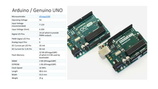
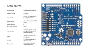
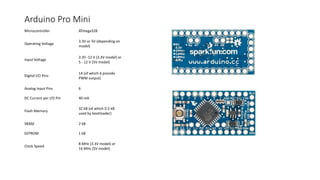
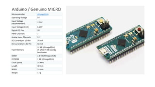
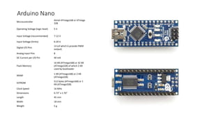
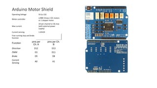
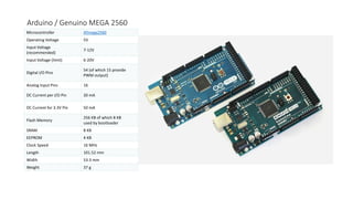
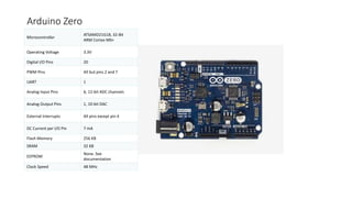
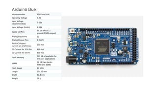
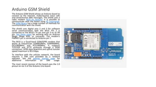
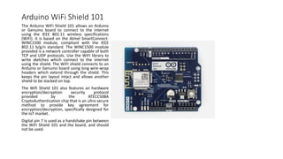
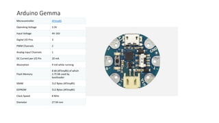
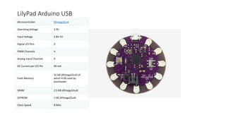
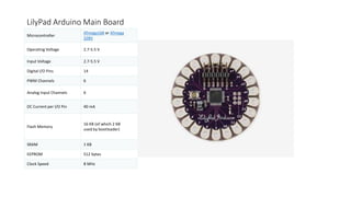
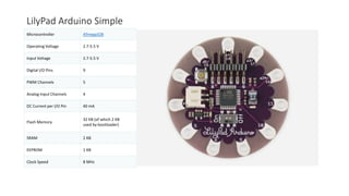
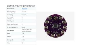
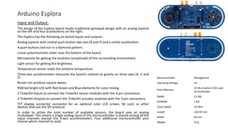
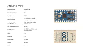
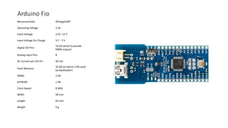
ENTRY LEVEL ARDUINO’S
• Arduino / Genuino UNO
• Arduino Pro
• Arduino Pro Mini
• Arduino / Genuino MICRO
• Arduino Nano
• Arduino / Genuino Starter Kit
• Arduino Basic Kit
• Arduino Motor Shield
Arduino / Genuino UNO
Microcontroller ATmega328P
Operating Voltage 5V
Input Voltage
(recommended)
7-12V
Input Voltage (limit) 6-20V
Digital I/O Pins
14 (of which 6 provide
PWM output)
PWM Digital I/O Pins 6
Analog Input Pins 6
DC Current per I/O Pin 20 mA
DC Current for 3.3V Pin 50 mA
Flash Memory
32 KB (ATmega328P)
of which 0.5 KB used by
bootloader
SRAM 2 KB (ATmega328P)
EEPROM 1 KB (ATmega328P)
Clock Speed 16 MHz
Length 68.6 mm
Width 53.4 mm
Weight 25 g
Arduino Pro
Microcontroller ATmega168 or ATmega328
Operating Voltage 3.3V or 5V
Input Voltage
3.35 -12 V (3.3V versions) or
5 - 12 V (5V versions)
Digital I/O Pins
14 (of which 6 provide PWM
output)
Analog Input Pins 6
DC Current per I/O Pin 40 mA
Flash Memory
16 KB (ATmega168) or 32KB
(ATmega328) of which 2 KB
used by bootloader
SRAM
1 KB (ATmega168) or 2 KB
(ATmega328)
EEPROM
512 bytes (ATmega168) or 1
KB (ATmega328)
Clock Speed
8 MHz (3.3V versions) or
16 MHz (5V versions)
Arduino Pro Mini
Microcontroller ATmega328
Operating Voltage
3.3V or 5V (depending on
model)
Input Voltage
3.35 -12 V (3.3V model) or
5 - 12 V (5V model)
Digital I/O Pins
14 (of which 6 provide
PWM output)
Analog Input Pins 6
DC Current per I/O Pin 40 mA
Flash Memory
32 kB (of which 0.5 kB
used by bootloader)
SRAM 2 kB
EEPROM 1 kB
Clock Speed
8 MHz (3.3V model) or
16 MHz (5V model)
Arduino / Genuino MICRO
Microcontroller ATmega32U4
Operating Voltage 5V
Input Voltage
(recommended)
7-12V
Input Voltage (limit) 6-20V
Digital I/O Pins 20
PWM Channels 7
Analog Input Channels 12
DC Current per I/O Pin 20 mA
DC Current for 3.3V Pin 50 mA
Flash Memory
32 KB (ATmega32U4)
of which 4 KB used by
bootloader
SRAM 2.5 KB (ATmega32U4)
EEPROM 1 KB (ATmega32U4)
Clock Speed 16 MHz
Length 48 mm
Width 18 mm
Weight 13 g
Arduino Nano
Microcontroller
Atmel ATmega168 or ATmega
328
Operating Voltage (logic level) 5 V
Input Voltage (recommended) 7-12 V
Input Voltage (limits) 6-20 V
Digital I/O Pins
14 (of which 6 provide PWM
output)
Analog Input Pins 8
DC Current per I/O Pin 40 mA
Flash Memory
16 KB (ATmega168) or 32 KB
(ATmega328) of which 2 KB
used by bootloader
SRAM
1 KB (ATmega168) or 2 KB
(ATmega328)
EEPROM
512 bytes (ATmega168) or 1
KB (ATmega328)
Clock Speed 16 MHz
Dimensions 0.73" x 1.70"
Length 45 mm
Width 18 mm
Weigth 5 g
Arduino Motor Shield
Operating Voltage 5V to 12V
Motor controller
L298P, Drives 2 DC motors
or 1 stepper motor
Max current
2A per channel or 4A max
(with external power
supply)
Current sensing 1.65V/A
Free running stop and brake
function
Function
pins per
Ch. A
pins per Ch.
B
Direction D12 D13
PWM D3 D11
Brake D9 D8
Current
Sensing
A0 A1
ENHANCED FEATURES
• Arduino / Genuino MEGA 2560
• Arduino Zero
• Arduino Due
• Arduino Proto Shield
Arduino / Genuino MEGA 2560
Microcontroller ATmega2560
Operating Voltage 5V
Input Voltage
(recommended)
7-12V
Input Voltage (limit) 6-20V
Digital I/O Pins
54 (of which 15 provide
PWM output)
Analog Input Pins 16
DC Current per I/O Pin 20 mA
DC Current for 3.3V Pin 50 mA
Flash Memory
256 KB of which 8 KB
used by bootloader
SRAM 8 KB
EEPROM 4 KB
Clock Speed 16 MHz
Length 101.52 mm
Width 53.3 mm
Weight 37 g
Arduino Zero
Microcontroller
ATSAMD21G18, 32-Bit
ARM Cortex M0+
Operating Voltage 3.3V
Digital I/O Pins 20
PWM Pins All but pins 2 and 7
UART 1
Analog Input Pins 6, 12-bit ADC channels
Analog Output Pins 1, 10-bit DAC
External Interrupts All pins except pin 4
DC Current per I/O Pin 7 mA
Flash Memory 256 KB
SRAM 32 KB
EEPROM
None. See
documentation
Clock Speed 48 MHz
Arduino Due
Microcontroller AT91SAM3X8E
Operating Voltage 3.3V
Input Voltage
(recommended)
7-12V
Input Voltage (limits) 6-16V
Digital I/O Pins
54 (of which 12
provide PWM output)
Analog Input Pins 12
Analog Output Pins 2 (DAC)
Total DC Output
Current on all I/O lines
130 mA
DC Current for 3.3V Pin 800 mA
DC Current for 5V Pin 800 mA
Flash Memory
512 KB all available for
the user applications
SRAM
96 KB (two banks:
64KB and 32KB)
Clock Speed 84 MHz
Length 101.52 mm
Width 53.3 mm
Weight 36 g
Arduino Proto Shield
The Arduino Prototyping Shield makes it easy
for you to design custom circuits. You can
solder parts to the prototyping area to create
your project, or use it with a small solderless
breadboard (not included) to quickly test
circuit ideas without having to solder. It's got
extra connections for all of the Arduino I/O
pins, and it's got space to mount through-
hole and surface mount integrated circuits.
It's a convenient way to make your custom
circuit and Arduino into a single module.
The wide prototyping area has some extra
features:1.0 Arduino Pinout
1 Reset Button
1 ICSP Connector
14 pin SMD footprint (50 mils pitch)
20 pin Through Hole footprint (100 mils
pitch)
INTERNET OF THINGS
• Arduino Yún
• Arduino Ethernet Shield
• Arduino GSM Shield
• Arduino WiFi Shield 101
Arduino Yún
AVR Arduino microcontroller
Microcontroller ATmega32U4
Operating Voltage 5V
Input Voltage 5
Digital I/O Pins 20
PWM Channels 7
Analog Input Pins 12
DC Current per I/O Pin 40 mA
DC Current for 3.3V Pin 50 mA
Flash Memory
32 KB (of which 4 KB used by
bootloader)
SRAM 2.5 KB
EEPROM 1 KB
Clock Speed 16 MHz
Linux Microprocessor
Processor Atheros AR9331
Architecture MIPS @400MHz
Operating Voltage 3.3V
Ethernet IEEE 802.3 10/100Mbit/s
WiFi IEEE 802.11b/g/n
USB Type-A 2.0 Host
Card Reader Micro-SD only
RAM 64 MB DDR2
Flash Memory 16 MB
SRAM 2.5 KB
EEPROM 1 KB
Clock Speed 16 MHz
PoE compatible 802.3af card support See Power
Arduino Ethernet Shield
The Arduino Ethernet Shield connects your
Arduino to the internet in mere minutes. Just
plug this module onto your Arduino board,
connect it to your network with an RJ45 cable
(not included) and follow a few simple
instructions to start controlling your world
through the internet. As always with Arduino,
every element of the platform – hardware,
software and documentation – is freely
available and open-source. This means you can
learn exactly how it's made and use its design as
the starting point for your own circuits.
Hundreds of thousands of Arduino boards are
already fueling people’s creativity all over the
world, everyday. Join us now, Arduino is you!
Requires an Arduino board (not included)
Operating voltage 5V (supplied from the
Arduino Board)
Ethernet Controller: W5100 with internal 16K
buffer
Connection speed: 10/100Mb
Connection with Arduino on SPI port
Arduino GSM Shield
The Arduino GSM Shield allows an Arduino board to
connect to the internet, make/receive voice calls
and send/receive SMS messages. The shield uses a
radio modem M10 by Quectel. It is possible to
communicate with the board using AT commands.
The GSM library has a large number of methods for
communication with the shield.
The shield uses digital pins 2 and 3 for software
serial communication with the M10. Pin 2 is
connected to the M10’s TX pin and pin 3 to its RX
pin. See these notes for working with an Arduino
Mega, Mega ADK, or Leonardo. The modem's
PWRKEY pin is connected to Arduino pin 7.
The M10 is a Quad-band GSM/GPRS modem that
works at frequencies GSM850MHz, GSM900MHz,
DCS1800MHz and PCS1900MHz. It supports
TCP/UDP and HTTP protocols through a GPRS
connection. GPRS data downlink and uplink transfer
speed maximum is 85.6 kbps.
To interface with the cellular network, the board
requires a SIM card provided by a network
operator. See the getting started page for
additional information on SIM usage.
The most recent revision of the board uses the 1.0
pinout on rev 3 of the Arduino Uno board.
Arduino WiFi Shield 101
The Arduino WiFi Shield 101 allows an Arduino
or Genuino board to connect to the internet
using the IEEE 802.11 wireless specifications
(WiFi). It is based on the Atmel SmartConnect-
WINC1500 module, compliant with the IEEE
802.11 b/g/n standard. The WINC1500 module
provided is a network controller capable of both
TCP and UDP protocols. Use the WiFI library to
write sketches which connect to the internet
using the shield. The WiFI shield connects to an
Arduino or Genuino board using long wire-wrap
headers which extend through the shield. This
keeps the pin layout intact and allows another
shield to be stacked on top.
The Wifi Shield 101 also features an hardware
encryption/decryption security protocol
provided by the ATECC508A
CryptoAuthentication chip that is an ultra secure
method to provide key agreement for
encryption/decryption, specifically designed for
the IoT market.
Digital pin 7 is used as a handshake pin between
the WiFi Shield 101 and the board, and should
not be used.
WEARABLE ARDUINO’S
• Arduino Gemma
• LilyPad Arduino USB
• LilyPad Arduino Main Board
• LilyPad Arduino Simple
• LilyPad Arduino SimpleSnap
Arduino Gemma
Microcontroller ATtiny85
Operating Voltage 3.3V
Input Voltage 4V-16V
Digital I/O Pins 3
PWM Channels 2
Analog Input Channels 1
DC Current per I/O Pin 20 mA
Absorption 9 mA while running
Flash Memory
8 kB (ATtiny85) of which
2.75 kB used by
bootloader
SRAM 512 Bytes (ATtiny85)
EEPROM 512 Bytes (ATtiny85)
Clock Speed 8 MHz
Diameter 27.94 mm
LilyPad Arduino USB
Microcontroller ATmega32u4
Operating Voltage 3.3V
Input Voltage 3.8V-5V
Digital I/O Pins 9
PWM Channels 4
Analog Input Channels 4
DC Current per I/O Pin 40 mA
Flash Memory
32 KB (ATmega32u4) of
which 4 KB used by
bootloader
SRAM 2.5 KB (ATmega32u4)
EEPROM 1 KB (ATmega32u4)
Clock Speed 8 MHz
LilyPad Arduino Main Board
Microcontroller
ATmega168 or ATmega
328V
Operating Voltage 2.7-5.5 V
Input Voltage 2.7-5.5 V
Digital I/O Pins 14
PWM Channels 6
Analog Input Channels 6
DC Current per I/O Pin 40 mA
Flash Memory
16 KB (of which 2 KB
used by bootloader)
SRAM 1 KB
EEPROM 512 bytes
Clock Speed 8 MHz
LilyPad Arduino Simple
Microcontroller ATmega328
Operating Voltage 2.7-5.5 V
Input Voltage 2.7-5.5 V
Digital I/O Pins 9
PWM Channels 5
Analog Input Channels 4
DC Current per I/O Pin 40 mA
Flash Memory
32 KB (of which 2 KB
used by bootloader)
SRAM 2 KB
EEPROM 1 KB
Clock Speed 8 MHz
LilyPad Arduino SimpleSnap
Microcontroller ATmega328
Operating Voltage 2.7-5.5 V
Input Voltage 2.7-5.5 V
Digital I/O Pins 9
PWM Channels 5
Analog Input Channels 4
DC Current per I/O Pin 40 mA
Flash Memory
32 KB (of which 2 KB
used by bootloader)
SRAM 2 KB
EEPROM 1 KB
Clock Speed 8 MHz
Radius 18 mm
3D PRINTING
• Arduino Materia 101
Arduino Materia 101
Color White
Body Stainless steel covered by white plexiglass
Carter Plexiglass
Screen LCD monitor (20x4)
Minimum layer thickness 0.1mm
Size 310x350x330 mm
Print Area 140x100x100 mm
Printing technology Fused Filament Fabrication
Suggested filament 1.75mm PLA
Experimental filaments
Cristal Flex, PLA termosense, TPU, PET, PLA Sand, PLA
Flex (1.75mm)
X & Y resolution 0.06 mm
Z resolution 0.1 mm
Extruder (diameter) 0.35 mm
PLA suggested temperature 195-220 °C
Absorption 65 W
Weight 10 kg
Extruder block with pressure adjustment on filament
Bearings recirculating ball on all axes
Z axis movement with trapezoidal screws
Adjustable printing plate
Micro USB to update the firmware
Possibility to print directly from SD card
Retired
• Arduino Robot
• Arduino Leonardo
• Arduino Esplora
• Arduino Mini
• Arduino Fio
• Arduino TFT LCD Screen
• Arduino ISP
Arduino Robot
Microcontroller ATmega32u4
Operating Voltage 5V
Input Voltage 5V through flat cable
Digital I/O Pins 5
PWM Channels 6
Analog Input Channels 4 (of the Digital I/O pins)
Analog Input Channels (multiplexed) 8
DC Current per I/O Pin 40 mA
Flash Memory
32 KB (ATmega32u4) of which 4 KB
used by bootloader
SRAM 2.5 KB (ATmega32u4)
EEPROM (internal) 1 KB (ATmega32u4)
EEPROM (external) 512 Kbit (I2C)
Clock Speed 16 MHz
Keypad 5 keys
Knob potentiomenter attached to analog pin
Full color LCD over SPI communication
SD card reader for FAT16 formatted cards
Speaker 8 Ohm
Digital Compass
provides deviation from the
geographical north in degrees
I2C soldering ports 3
Prototyping areas 4
Radius 185 mm
Heigth 85 mm
Arduino Leonardo
Microcontroller ATmega32u4
Operating Voltage 5V
Input Voltage
(recommended)
7-12V
Input Voltage (limits) 6-20V
Digital I/O Pins 20
PWM Channels 7
Analog Input Channels 12
DC Current per I/O Pin 40 mA
DC Current for 3.3V Pin 50 mA
Flash Memory
32 KB (ATmega32u4) of
which 4 KB used by
bootloader
SRAM 2.5 KB (ATmega32u4)
EEPROM 1 KB (ATmega32u4)
Clock Speed 16 MHz
Length 68.6 mm
Width 53.3 mm
Weight 20g
Arduino Esplora
Input and Output :
The design of the Esplora board recalls traditional gamepad design with an analog joystick
on the left and four pushbuttons on the right.
The Esplora has the following on-board inputs and outputs :
Analog joystick with central push-button two axis (X and Y) and a center pushbutton.
4 push-buttons laid out in a diamond pattern.
Linear potentiometer slider near the bottom of the board.
Microphone for getting the loudness (amplitude) of the surrounding environment.
Light sensor for getting the brightness.
Temperature sensor reads the ambient temperature
Three-axis accelerometer measures the board's relation to gravity on three axes (X, Y, and
Z)
Buzzer can produce square-waves.
RGB led bright LED with Red Green and Blue elements for color mixing.
2 TinkerKit Inputs to connect the TinkerKit sensor modules with the 3-pin connectors.
2 TinkerKit Outputs to connect the TinkerKit actuator modules with the 3-pin connectors.
TFT display connector connector for an optional color LCD screen, SD card, or other
devices that use the SPI protocol.
In order to utilize the total number of available sensors, the board uses an analog
multiplexer. This means a single analog input of the microcontroller is shared among all the
input channels (except the 3-axis accelerometer). Four additional microcontroller pins
choose which channel to read.
Microcontroller ATmega32u4
Operating Voltage 5V
Flash Memory
32 KB of which 4 KB used
by bootloader
SRAM 2.5 KB
EEPROM 1 KB
Clock Speed 16 MHz
Lenght 164.04 mm
Width 60 mm
Weight 53 g
Arduino Mini
Microcontroller ATmega328
Operating Voltage 5V
Input Voltage 7-9 V
Digital I/O Pins
14 (of which 6 provide
PWM output)
Analog Input Pins
8 (of which 4 are broken
out onto pins)
DC Current per I/O Pin 40 mA
Flash Memory
32 KB (of which 2 KB used
by bootloader)
SRAM 2 KB
EEPROM 1 KB
Clock Speed 16 MHz
Length 30 mm
Width 18 mm
Arduino Fio
Microcontroller ATmega328P
Operating Voltage 3.3V
Input Voltage 3.35 -12 V
Input Voltage for Charge 3.7 - 7 V
Digital I/O Pins
14 (of which 6 provide
PWM output)
Analog Input Pins 8
DC Current per I/O Pin 40 mA
Flash Memory
32 KB (of which 2 KB used
by bootloader)
SRAM 2 KB
EEPROM 1 KB
Clock Speed 8 MHz
Width 28 mm
Length 65 mm
Weigth 9 g
Arduino TFT LCD Screen
The screen is 1.77" diagonal, with 160 x 128
pixel resolution. The TFT library interfaces
with the screen's controller through SPI
when using the TFT library. Refer to
the screen's data sheet for complete details.
The screen runs on +5 VDC
The micro-SD slot is accessible through
the SD card library.
The LED backlight is dimmable by PWM.
The screen's headers are laid out so it easily
sockets into the Arduino Esplora and Arduino
Robot.
ALINTIDIR
https://www.arduino.cc/en/Main/Products adresinden yararlanarak
hazırlanmıştır.

Arduino Model's

  • 1.
    ENTRY LEVEL ARDUINO’S •Arduino / Genuino UNO • Arduino Pro • Arduino Pro Mini • Arduino / Genuino MICRO • Arduino Nano • Arduino / Genuino Starter Kit • Arduino Basic Kit • Arduino Motor Shield
  • 2.
    Arduino / GenuinoUNO Microcontroller ATmega328P Operating Voltage 5V Input Voltage (recommended) 7-12V Input Voltage (limit) 6-20V Digital I/O Pins 14 (of which 6 provide PWM output) PWM Digital I/O Pins 6 Analog Input Pins 6 DC Current per I/O Pin 20 mA DC Current for 3.3V Pin 50 mA Flash Memory 32 KB (ATmega328P) of which 0.5 KB used by bootloader SRAM 2 KB (ATmega328P) EEPROM 1 KB (ATmega328P) Clock Speed 16 MHz Length 68.6 mm Width 53.4 mm Weight 25 g
  • 3.
    Arduino Pro Microcontroller ATmega168or ATmega328 Operating Voltage 3.3V or 5V Input Voltage 3.35 -12 V (3.3V versions) or 5 - 12 V (5V versions) Digital I/O Pins 14 (of which 6 provide PWM output) Analog Input Pins 6 DC Current per I/O Pin 40 mA Flash Memory 16 KB (ATmega168) or 32KB (ATmega328) of which 2 KB used by bootloader SRAM 1 KB (ATmega168) or 2 KB (ATmega328) EEPROM 512 bytes (ATmega168) or 1 KB (ATmega328) Clock Speed 8 MHz (3.3V versions) or 16 MHz (5V versions)
  • 4.
    Arduino Pro Mini MicrocontrollerATmega328 Operating Voltage 3.3V or 5V (depending on model) Input Voltage 3.35 -12 V (3.3V model) or 5 - 12 V (5V model) Digital I/O Pins 14 (of which 6 provide PWM output) Analog Input Pins 6 DC Current per I/O Pin 40 mA Flash Memory 32 kB (of which 0.5 kB used by bootloader) SRAM 2 kB EEPROM 1 kB Clock Speed 8 MHz (3.3V model) or 16 MHz (5V model)
  • 5.
    Arduino / GenuinoMICRO Microcontroller ATmega32U4 Operating Voltage 5V Input Voltage (recommended) 7-12V Input Voltage (limit) 6-20V Digital I/O Pins 20 PWM Channels 7 Analog Input Channels 12 DC Current per I/O Pin 20 mA DC Current for 3.3V Pin 50 mA Flash Memory 32 KB (ATmega32U4) of which 4 KB used by bootloader SRAM 2.5 KB (ATmega32U4) EEPROM 1 KB (ATmega32U4) Clock Speed 16 MHz Length 48 mm Width 18 mm Weight 13 g
  • 6.
    Arduino Nano Microcontroller Atmel ATmega168or ATmega 328 Operating Voltage (logic level) 5 V Input Voltage (recommended) 7-12 V Input Voltage (limits) 6-20 V Digital I/O Pins 14 (of which 6 provide PWM output) Analog Input Pins 8 DC Current per I/O Pin 40 mA Flash Memory 16 KB (ATmega168) or 32 KB (ATmega328) of which 2 KB used by bootloader SRAM 1 KB (ATmega168) or 2 KB (ATmega328) EEPROM 512 bytes (ATmega168) or 1 KB (ATmega328) Clock Speed 16 MHz Dimensions 0.73" x 1.70" Length 45 mm Width 18 mm Weigth 5 g
  • 7.
    Arduino Motor Shield OperatingVoltage 5V to 12V Motor controller L298P, Drives 2 DC motors or 1 stepper motor Max current 2A per channel or 4A max (with external power supply) Current sensing 1.65V/A Free running stop and brake function Function pins per Ch. A pins per Ch. B Direction D12 D13 PWM D3 D11 Brake D9 D8 Current Sensing A0 A1
  • 8.
    ENHANCED FEATURES • Arduino/ Genuino MEGA 2560 • Arduino Zero • Arduino Due • Arduino Proto Shield
  • 9.
    Arduino / GenuinoMEGA 2560 Microcontroller ATmega2560 Operating Voltage 5V Input Voltage (recommended) 7-12V Input Voltage (limit) 6-20V Digital I/O Pins 54 (of which 15 provide PWM output) Analog Input Pins 16 DC Current per I/O Pin 20 mA DC Current for 3.3V Pin 50 mA Flash Memory 256 KB of which 8 KB used by bootloader SRAM 8 KB EEPROM 4 KB Clock Speed 16 MHz Length 101.52 mm Width 53.3 mm Weight 37 g
  • 10.
    Arduino Zero Microcontroller ATSAMD21G18, 32-Bit ARMCortex M0+ Operating Voltage 3.3V Digital I/O Pins 20 PWM Pins All but pins 2 and 7 UART 1 Analog Input Pins 6, 12-bit ADC channels Analog Output Pins 1, 10-bit DAC External Interrupts All pins except pin 4 DC Current per I/O Pin 7 mA Flash Memory 256 KB SRAM 32 KB EEPROM None. See documentation Clock Speed 48 MHz
  • 11.
    Arduino Due Microcontroller AT91SAM3X8E OperatingVoltage 3.3V Input Voltage (recommended) 7-12V Input Voltage (limits) 6-16V Digital I/O Pins 54 (of which 12 provide PWM output) Analog Input Pins 12 Analog Output Pins 2 (DAC) Total DC Output Current on all I/O lines 130 mA DC Current for 3.3V Pin 800 mA DC Current for 5V Pin 800 mA Flash Memory 512 KB all available for the user applications SRAM 96 KB (two banks: 64KB and 32KB) Clock Speed 84 MHz Length 101.52 mm Width 53.3 mm Weight 36 g
  • 12.
    Arduino Proto Shield TheArduino Prototyping Shield makes it easy for you to design custom circuits. You can solder parts to the prototyping area to create your project, or use it with a small solderless breadboard (not included) to quickly test circuit ideas without having to solder. It's got extra connections for all of the Arduino I/O pins, and it's got space to mount through- hole and surface mount integrated circuits. It's a convenient way to make your custom circuit and Arduino into a single module. The wide prototyping area has some extra features:1.0 Arduino Pinout 1 Reset Button 1 ICSP Connector 14 pin SMD footprint (50 mils pitch) 20 pin Through Hole footprint (100 mils pitch)
  • 13.
    INTERNET OF THINGS •Arduino Yún • Arduino Ethernet Shield • Arduino GSM Shield • Arduino WiFi Shield 101
  • 14.
    Arduino Yún AVR Arduinomicrocontroller Microcontroller ATmega32U4 Operating Voltage 5V Input Voltage 5 Digital I/O Pins 20 PWM Channels 7 Analog Input Pins 12 DC Current per I/O Pin 40 mA DC Current for 3.3V Pin 50 mA Flash Memory 32 KB (of which 4 KB used by bootloader) SRAM 2.5 KB EEPROM 1 KB Clock Speed 16 MHz Linux Microprocessor Processor Atheros AR9331 Architecture MIPS @400MHz Operating Voltage 3.3V Ethernet IEEE 802.3 10/100Mbit/s WiFi IEEE 802.11b/g/n USB Type-A 2.0 Host Card Reader Micro-SD only RAM 64 MB DDR2 Flash Memory 16 MB SRAM 2.5 KB EEPROM 1 KB Clock Speed 16 MHz PoE compatible 802.3af card support See Power
  • 15.
    Arduino Ethernet Shield TheArduino Ethernet Shield connects your Arduino to the internet in mere minutes. Just plug this module onto your Arduino board, connect it to your network with an RJ45 cable (not included) and follow a few simple instructions to start controlling your world through the internet. As always with Arduino, every element of the platform – hardware, software and documentation – is freely available and open-source. This means you can learn exactly how it's made and use its design as the starting point for your own circuits. Hundreds of thousands of Arduino boards are already fueling people’s creativity all over the world, everyday. Join us now, Arduino is you! Requires an Arduino board (not included) Operating voltage 5V (supplied from the Arduino Board) Ethernet Controller: W5100 with internal 16K buffer Connection speed: 10/100Mb Connection with Arduino on SPI port
  • 16.
    Arduino GSM Shield TheArduino GSM Shield allows an Arduino board to connect to the internet, make/receive voice calls and send/receive SMS messages. The shield uses a radio modem M10 by Quectel. It is possible to communicate with the board using AT commands. The GSM library has a large number of methods for communication with the shield. The shield uses digital pins 2 and 3 for software serial communication with the M10. Pin 2 is connected to the M10’s TX pin and pin 3 to its RX pin. See these notes for working with an Arduino Mega, Mega ADK, or Leonardo. The modem's PWRKEY pin is connected to Arduino pin 7. The M10 is a Quad-band GSM/GPRS modem that works at frequencies GSM850MHz, GSM900MHz, DCS1800MHz and PCS1900MHz. It supports TCP/UDP and HTTP protocols through a GPRS connection. GPRS data downlink and uplink transfer speed maximum is 85.6 kbps. To interface with the cellular network, the board requires a SIM card provided by a network operator. See the getting started page for additional information on SIM usage. The most recent revision of the board uses the 1.0 pinout on rev 3 of the Arduino Uno board.
  • 17.
    Arduino WiFi Shield101 The Arduino WiFi Shield 101 allows an Arduino or Genuino board to connect to the internet using the IEEE 802.11 wireless specifications (WiFi). It is based on the Atmel SmartConnect- WINC1500 module, compliant with the IEEE 802.11 b/g/n standard. The WINC1500 module provided is a network controller capable of both TCP and UDP protocols. Use the WiFI library to write sketches which connect to the internet using the shield. The WiFI shield connects to an Arduino or Genuino board using long wire-wrap headers which extend through the shield. This keeps the pin layout intact and allows another shield to be stacked on top. The Wifi Shield 101 also features an hardware encryption/decryption security protocol provided by the ATECC508A CryptoAuthentication chip that is an ultra secure method to provide key agreement for encryption/decryption, specifically designed for the IoT market. Digital pin 7 is used as a handshake pin between the WiFi Shield 101 and the board, and should not be used.
  • 18.
    WEARABLE ARDUINO’S • ArduinoGemma • LilyPad Arduino USB • LilyPad Arduino Main Board • LilyPad Arduino Simple • LilyPad Arduino SimpleSnap
  • 19.
    Arduino Gemma Microcontroller ATtiny85 OperatingVoltage 3.3V Input Voltage 4V-16V Digital I/O Pins 3 PWM Channels 2 Analog Input Channels 1 DC Current per I/O Pin 20 mA Absorption 9 mA while running Flash Memory 8 kB (ATtiny85) of which 2.75 kB used by bootloader SRAM 512 Bytes (ATtiny85) EEPROM 512 Bytes (ATtiny85) Clock Speed 8 MHz Diameter 27.94 mm
  • 20.
    LilyPad Arduino USB MicrocontrollerATmega32u4 Operating Voltage 3.3V Input Voltage 3.8V-5V Digital I/O Pins 9 PWM Channels 4 Analog Input Channels 4 DC Current per I/O Pin 40 mA Flash Memory 32 KB (ATmega32u4) of which 4 KB used by bootloader SRAM 2.5 KB (ATmega32u4) EEPROM 1 KB (ATmega32u4) Clock Speed 8 MHz
  • 21.
    LilyPad Arduino MainBoard Microcontroller ATmega168 or ATmega 328V Operating Voltage 2.7-5.5 V Input Voltage 2.7-5.5 V Digital I/O Pins 14 PWM Channels 6 Analog Input Channels 6 DC Current per I/O Pin 40 mA Flash Memory 16 KB (of which 2 KB used by bootloader) SRAM 1 KB EEPROM 512 bytes Clock Speed 8 MHz
  • 22.
    LilyPad Arduino Simple MicrocontrollerATmega328 Operating Voltage 2.7-5.5 V Input Voltage 2.7-5.5 V Digital I/O Pins 9 PWM Channels 5 Analog Input Channels 4 DC Current per I/O Pin 40 mA Flash Memory 32 KB (of which 2 KB used by bootloader) SRAM 2 KB EEPROM 1 KB Clock Speed 8 MHz
  • 23.
    LilyPad Arduino SimpleSnap MicrocontrollerATmega328 Operating Voltage 2.7-5.5 V Input Voltage 2.7-5.5 V Digital I/O Pins 9 PWM Channels 5 Analog Input Channels 4 DC Current per I/O Pin 40 mA Flash Memory 32 KB (of which 2 KB used by bootloader) SRAM 2 KB EEPROM 1 KB Clock Speed 8 MHz Radius 18 mm
  • 24.
  • 25.
    Arduino Materia 101 ColorWhite Body Stainless steel covered by white plexiglass Carter Plexiglass Screen LCD monitor (20x4) Minimum layer thickness 0.1mm Size 310x350x330 mm Print Area 140x100x100 mm Printing technology Fused Filament Fabrication Suggested filament 1.75mm PLA Experimental filaments Cristal Flex, PLA termosense, TPU, PET, PLA Sand, PLA Flex (1.75mm) X & Y resolution 0.06 mm Z resolution 0.1 mm Extruder (diameter) 0.35 mm PLA suggested temperature 195-220 °C Absorption 65 W Weight 10 kg Extruder block with pressure adjustment on filament Bearings recirculating ball on all axes Z axis movement with trapezoidal screws Adjustable printing plate Micro USB to update the firmware Possibility to print directly from SD card
  • 26.
    Retired • Arduino Robot •Arduino Leonardo • Arduino Esplora • Arduino Mini • Arduino Fio • Arduino TFT LCD Screen • Arduino ISP
  • 27.
    Arduino Robot Microcontroller ATmega32u4 OperatingVoltage 5V Input Voltage 5V through flat cable Digital I/O Pins 5 PWM Channels 6 Analog Input Channels 4 (of the Digital I/O pins) Analog Input Channels (multiplexed) 8 DC Current per I/O Pin 40 mA Flash Memory 32 KB (ATmega32u4) of which 4 KB used by bootloader SRAM 2.5 KB (ATmega32u4) EEPROM (internal) 1 KB (ATmega32u4) EEPROM (external) 512 Kbit (I2C) Clock Speed 16 MHz Keypad 5 keys Knob potentiomenter attached to analog pin Full color LCD over SPI communication SD card reader for FAT16 formatted cards Speaker 8 Ohm Digital Compass provides deviation from the geographical north in degrees I2C soldering ports 3 Prototyping areas 4 Radius 185 mm Heigth 85 mm
  • 28.
    Arduino Leonardo Microcontroller ATmega32u4 OperatingVoltage 5V Input Voltage (recommended) 7-12V Input Voltage (limits) 6-20V Digital I/O Pins 20 PWM Channels 7 Analog Input Channels 12 DC Current per I/O Pin 40 mA DC Current for 3.3V Pin 50 mA Flash Memory 32 KB (ATmega32u4) of which 4 KB used by bootloader SRAM 2.5 KB (ATmega32u4) EEPROM 1 KB (ATmega32u4) Clock Speed 16 MHz Length 68.6 mm Width 53.3 mm Weight 20g
  • 29.
    Arduino Esplora Input andOutput : The design of the Esplora board recalls traditional gamepad design with an analog joystick on the left and four pushbuttons on the right. The Esplora has the following on-board inputs and outputs : Analog joystick with central push-button two axis (X and Y) and a center pushbutton. 4 push-buttons laid out in a diamond pattern. Linear potentiometer slider near the bottom of the board. Microphone for getting the loudness (amplitude) of the surrounding environment. Light sensor for getting the brightness. Temperature sensor reads the ambient temperature Three-axis accelerometer measures the board's relation to gravity on three axes (X, Y, and Z) Buzzer can produce square-waves. RGB led bright LED with Red Green and Blue elements for color mixing. 2 TinkerKit Inputs to connect the TinkerKit sensor modules with the 3-pin connectors. 2 TinkerKit Outputs to connect the TinkerKit actuator modules with the 3-pin connectors. TFT display connector connector for an optional color LCD screen, SD card, or other devices that use the SPI protocol. In order to utilize the total number of available sensors, the board uses an analog multiplexer. This means a single analog input of the microcontroller is shared among all the input channels (except the 3-axis accelerometer). Four additional microcontroller pins choose which channel to read. Microcontroller ATmega32u4 Operating Voltage 5V Flash Memory 32 KB of which 4 KB used by bootloader SRAM 2.5 KB EEPROM 1 KB Clock Speed 16 MHz Lenght 164.04 mm Width 60 mm Weight 53 g
  • 30.
    Arduino Mini Microcontroller ATmega328 OperatingVoltage 5V Input Voltage 7-9 V Digital I/O Pins 14 (of which 6 provide PWM output) Analog Input Pins 8 (of which 4 are broken out onto pins) DC Current per I/O Pin 40 mA Flash Memory 32 KB (of which 2 KB used by bootloader) SRAM 2 KB EEPROM 1 KB Clock Speed 16 MHz Length 30 mm Width 18 mm
  • 31.
    Arduino Fio Microcontroller ATmega328P OperatingVoltage 3.3V Input Voltage 3.35 -12 V Input Voltage for Charge 3.7 - 7 V Digital I/O Pins 14 (of which 6 provide PWM output) Analog Input Pins 8 DC Current per I/O Pin 40 mA Flash Memory 32 KB (of which 2 KB used by bootloader) SRAM 2 KB EEPROM 1 KB Clock Speed 8 MHz Width 28 mm Length 65 mm Weigth 9 g
  • 32.
    Arduino TFT LCDScreen The screen is 1.77" diagonal, with 160 x 128 pixel resolution. The TFT library interfaces with the screen's controller through SPI when using the TFT library. Refer to the screen's data sheet for complete details. The screen runs on +5 VDC The micro-SD slot is accessible through the SD card library. The LED backlight is dimmable by PWM. The screen's headers are laid out so it easily sockets into the Arduino Esplora and Arduino Robot.
  • 33.