2. 2
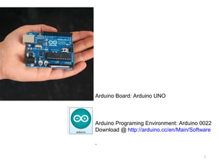
*Download Arduino Software from Arduino.cc and unzip the folder to your computer. A
file within the folder called Arduino, allows you to launch the programming environment.
*You need to install a driver that comes with Arduino to be able to communicate with
the board
3. 3
USB
7-12 v
3 v
GRD
5 v
Analog Input Pins
Digital Input/Output Pins
Pins with ~ are PWM
[Analog Output]
GRD
Transmitter/Receiver
Serial Connection
Microcontroller ATmega328
Operating Voltage 5V
Input Voltage (recommended)7-12V
Input Voltage (limits)6-20V
Digital I/O Pins 14
(of which 6 provide PWM output)
Analog Input Pins 6
DC Current per I/O Pin 40 mA
DC Current for 3.3V Pin 50 mA
7. Other Hardware Choices-Boards
Arduino BT
The Arduino BT is an Arduino board with built-in bluetooth module,
allowing for wireless communication.
LilyPad Arduino
The LilyPad Arduino is a microcontroller board designed for wearables
and e-textiles. It can be sewn to fabric and similarly mounted power
supplies, sensors and actuators with conductive thread.
Arduino Nano
Arduino Nano is a surface mount breadboard embedded version with
integrated USB. It is a smallest, complete, and breadboard friendly. It
has everything that Diecimila has (electrically) with more analog input
pins and onboard +5V AREF jumper.
7
8. Other Hardware Choices-SheildsXbee Shield
The Xbee shield allows an Arduino board to communicate wirelessly using Zigbee. The module can
communicate up to 100 feet indoors or 300 feet outdoors (with line-of-sight). It can be used as a
serial/usb replacement or you can put it into a command mode and configure it for a variety of
broadcast and mesh networking options.
The Xbee shield was created in collaboration with Libelium, who developed it for use in their SquidBee
motes (used for creating sensor networks).
Adafruit Servo/Stepper/DC Motor shield
A shield that can control 2 hobby servos and up to 2 unipolar/bipolar stepper motors or 4 bi-directional
DC motors.
Battery Shield
A shield from Liquidware that connects to the back of the Arduino, with a USB-rechargable lithium ion
battery that can power an Arduino for 14-28 hours depending on the circuit
Liquidware TouchShield
OLED touch screen shield.
Adafruit Wave shield
Plays any size 22KHz audio files from an SD memory card for music, effects and interactive sound art
Adafruit GPS & Datalogging shield
Connects up a GPS module and can log location, time/date as well as sensor data to an SD memory
flash card.
Adafruit XPort/Ethernet shield
Allows use of an XPort module for connecting to the Internet as a client or server. 8
9. Other Hardware Choices-Sheilds
Adafruit GPS & Datalogging shield
Connects up a GPS module and can log location,
time/date as well as sensor data to an SD memory
flash card.
Adafruit XPort/Ethernet shield
Allows use of an XPort module for connecting to the
Internet as a client or server.
http://ladyada.net
9
10. Other Hardware Choices-Sheilds
Liquidware TouchShield
OLED touch screen shield.
http://www.liquidware.com
Adafruit Servo/Stepper/DC Motor shield
A shield that can control 2 hobby servos and up to 2
unipolar/bipolar stepper motors or 4 bi-directional
DC motors.
http://ladyada.net
10
11. USB Cable A to B - 6 and 10 Feet/ USB miniB Cable - 6 Foot
This USB Cable type is the one that allows for connecting normal Arduino Boards to the computer. They come in black and white and in various lengths. For
Arduino Mini Pro and Lilypad you need USB miniB for connecting to computer.
http://www.sparkfun.com/commerce/product_info.php?products_id=512
http://www.sparkfun.com/commerce/product_info.php?products_id=513
http://www.sparkfun.com/commerce/product_info.php?products_id=598
12. USB Cable Extension - 6 Foot/ USB Cable A to A - 6 and 10 Foot
These extension cables have a type A male connector on one end that plugs into any computer. The opposing end has a female type A connector allowing a
second USB cable to be inserted. This allows as many cables to be daisy chained together as needed. May come in White or Black, and in 6 feet. For more
extension you can combine USB cable extension with a USB A to A cable.
http://www.sparkfun.com/commerce/product_info.php?products_id=517
http://www.sparkfun.com/commerce/product_info.php?products_id=516
http://www.sparkfun.com/commerce/product_info.php?products_id=515
13. Arduino Boards
This is the new Arduino Uno. In addition to all the features of the previous board, the Uno now uses an ATmega8U2 instead of the FTDI chip. This allows for
faster transfer rates, no drivers needed for Linux or Mac (inf file for Windows is needed), and the ability to have the Uno show up as a keyboard, mouse,
joystick, etc.
The Arduino Mega is a microcontroller board based on the ATmega2560. It has 54 digital input/output pins (of which 14 can be used as PWM outputs), 16
analog inputs, 4 UARTs (hardware serial ports), a 16 MHz crystal oscillator, a USB connection, a power jack, an ICSP header, and a reset button. It contains
everything needed to support the microcontroller; simply connect it to a computer with a USB cable or power it with a AC-to-DC adapter or battery to get started.
The Mega is compatible with most shields designed for the Arduino Duemilanove or Diecimila. This is the new Arduino Mega 2560. In addition to all the features
of the previous board, the Mega 2560 now uses an ATmega8U2 instead of the FTDI chip. This allows for faster transfer rates, no drivers needed for Linux or
Mac (inf file for Windows is needed), and the ability to have the board show up as a keyboard, mouse, joystick, etc. It also has twice as much flash memory.
Other variaitions of arduino are Arduino pro, Arduino Mini Pro and Lilypad Arduino .
http://www.sparkfun.com/commerce/product_info.php?products_id=9950
http://www.sparkfun.com/commerce/product_info.php?products_id=9949
http://www.sparkfun.com/commerce/tutorial_info.php?tutorials_id=148
14. Arduino Project Enclosure/ Crib for Arduino - Metal Enclosure
The Arduino enclosure allows you to easily enclose your Arduino main board, Arduino Mega, or any other board that fits the Arduino foot print (FEZ Domino,
FEZ Panda, Netduino, etc). It simply presses shut, so you don't have to worry about screws or fasteners. It has room internally for an Arduino and a shield. It
even has a removable tab mated for use with an Ethernet shield. It also has a snap-in compartment in the back for accessing switches or connections or battery
access.
Made from sturdy, lightweight powder-coated aluminum, the Crib for Arduino can accommodate either an Arduino Duemilanove or Arduino Mega with head
room to spare for a shield like an Ethernet shield. This enclosure weighs only 5.6 oz (159 g) and is structurally very strong. The baseplate is pre-drilled with hole
patterns for both Arduino boards(Main and Mega so you get perfect alignment and no hole drilling for board mounting. Use the snap-in standoffs to quickly
mount your board and go. Flanges on the lid let you mount your project anywhere with just 4 screws. Bolt it securely under your desk or to the ceiling! Or just
insert four rubber feet (not included) into the flange holes so your Arduino project can sit on your desk and not scratch it.
http://www.sparkfun.com/commerce/product_info.php?products_id=10088
http://www.sparkfun.com/commerce/product_info.php?products_id=10033
15. Wall Adapter Power Supply - 9VDC 650mA/ Wall Adapter Power Supply - 12VDC 600mA
9VDC is High quality switching 'wall wart' AC to DC 9V 650mA wall power supply manufactured specifically for Spark Fun Electronics. These are switch mode
power supplies which mean the output is regulated to 9V and the capable output current is much higher (650mA!). These will power most projects that don't
require more than 650mA of current. Center-positive 5.5x2.1mm barrel connector.
Works with 100-240VAC inputs.
12VDC is a high quality AC to DC 'wall wart' which produces a regulated output of 12VDC at up to 600mA. These are switch mode power supplies which means
the output is regulated to 12V and the capable output current is much higher (600mA!). These will power most projects that don't require more than 650mA of
current. Center-positive 5.5x2.1mm barrel connector. Works with 100-240VAC inputs.
http://www.sparkfun.com/commerce/product_info.php?products_id=298
http://www.sparkfun.com/commerce/product_info.php?products_id=9442
16. 9V to Barrel Jack Adapter
Plug a 9V battery into one end and connect the other end to anything with a 5.5x2.1mm, center-positive barrel jack. Use this cable to battery-power any device
that needs 9V and has an on-board barrel jack - it works great for Arduinos, development boards, evaluation boards, and more!
http://www.sparkfun.com/commerce/product_info.php?products_id=9518
17. Battery Holder - 4xAA to Barrel Jack Connector
This is a simple 4 cell AA battery holder. The 5 inch cable is terminated with a standard 5.5x2.1mm, center positive barrel jack connector. The connector mates
with the barrel jack on the Arduino (among a number of other products) allowing you to easily make your project battery powered. Note: the average voltage
regulator has about 1V of dropout (but can vary greatly). This pack, with normal alkaline batteries, will output ~5.5V causing a normal 5V board to run at around
4 to 4.5V. This depends a lot of what board and processor you are using with the battery pack. Please consult your datasheet.
http://www.sparkfun.com/commerce/product_info.php?products_id=9835
18. 9V Solar & battery power supply
The 9V Solar & battery power supply is specially designed for Arduino and other microcontroller project alike. It can be used as a portable power supply, and is
capable of delivering 9V, 500mA power. It can be charged by your PCB USB port or by sun-light or in-door light sources. It has following features:
http://www.nuelectronics.com/estore/index.php?main_page=product_info&products_id=13
19. Long life Lithium Backpack Batteries for Arduino
These are long-life batteries particularly designed for Arduino. There is also a variation for Arduino Mega. Depending on how much juice you need, get these in
low, medium, or high capacity. Bare battery PCB matches the size of the Arduino . High Capacity 2200mAh Lithium Ion Battery provides 29 Standby Arduino
Hours. Medium Capacity 1000mAh Lithium Ion Battery provides 15 Standby Arduino Hours. Low Capacity 600mAh Lithium Ion Battery provides 9.4 Standby
Arduino Hours. It is rechargeable via Arduino USB or via USB Tybe-B Mini Cable and supplies regulated 5V and 3.3V .
http://www.liquidware.com/shop/show/bp/lithium+backpack
http://www.liquidware.com/shop/show/BPM/
http://antipastohw.blogspot.com/2008/06/how-to-install-lithium-backpack-to-your.html
20. Jumper wires with F/F, F/M and M/M connecting ends
These are easy to use jumper wires terminated as male to female, male to male or female to female for connections.
http://www.sparkfun.com/commerce/product_info.php?products_id=9386
http://www.sparkfun.com/commerce/product_info.php?products_id=8431
http://www.sparkfun.com/commerce/product_info.php?products_id=8430
21. Color Coded Flat (Ribbon)/Coded Flat (Ribbon)
These are easy to use jumper wires terminated as male to female, male to male or female to female for connections.
http://www.newark.com/jsp/search/productdetail.jsp?SKU=23M8844&CMP=AFC-GB100000001
http://www.allelectronics.com/make-a-store/item/RCBL-10TF/10-CONDUCTOR-TWIST-FLAT-RIBBON-CABLE/1.html
http://www.allelectronics.com/make-a-store/item/RCBL-9/9-CONDUCTOR-FLAT-RIBBON-CABLE/1.html
http://solutions.3m.com/wps/portal/3M/en_US/Interconnect/Home/Products/ProductCatalog/Catalog/?
PC_7_RJH9U5230O73D0ISNF9B3C3SI1_nid=855TBYZXVNit6Z44P5GPWMglD2FDQK85M6bl
22. Conductive Thread
Conductive thread is a creative way to connect various electronics onto clothing. This thread can carry current for power and signals. While not as conductive as
traces on a printed circuit board (PCB), this thread makes wearable clothing 'wearable'!
http://www.sparkfun.com/commerce/product_info.php?products_id=8544
http://www.sparkfun.com/commerce/product_info.php?products_id=8549
23. Protoboard
Protoboards provide a free canvass for devising soldered circuit compositions. They come in different colors and sizes.
http://www.sparkfun.com/commerce/product_info.php?products_id=8619
http://www.sparkfun.com/commerce/product_info.php?products_id=8708
http://www.sparkfun.com/commerce/product_info.php?products_id=8808
http://www.sparkfun.com/commerce/product_info.php?products_id=8814
http://www.sparkfun.com/commerce/product_info.php?products_id=8809
http://www.sparkfun.com/commerce/product_info.php?products_id=8847
http://www.sparkfun.com/commerce/product_info.php?products_id=8885
http://www.sparkfun.com/commerce/product_info.php?products_id=8887
24. Solderless Breadboard
To free yourself from the pain of soldering and also from the risk of ruining your components it is advisable to your breadboards. Breadboards come in different
sizes and even colors
http://www.sparkfun.com/commerce/product_info.php?products_id=9567
http://www.sparkfun.com/commerce/product_info.php?products_id=8800
http://www.sparkfun.com/commerce/product_info.php?products_id=8802
http://www.sparkfun.com/commerce/product_info.php?products_id=8803
http://www.sparkfun.com/commerce/product_info.php?products_id=137
http://www.sparkfun.com/commerce/product_info.php?products_id=7916
25. Breadboard Power Supply Stick 5V/3.3V
This is a very simple board that takes a 6-12V input voltage and outputs a selectable 5V or 3.3V regulated voltage. All headers are 0.1" pitch for simple insertion
into a breadboard. Input power can be supplied to either the DC barrel jack or the two pin header labeled + and -. Output power is supplied to the pins labeled
GND and VCC. Board has both an On/Off switch and a voltage select switch (3.3V/5V).
http://www.sparkfun.com/commerce/product_info.php?products_id=9319
26. Micro SD Shield –Data Logger Shield for Arduino
Running out of memory space in your Arduino project? The microSD Shield equips your Arduino with mass-storage capability, so you can use it for data-logging
or other related projects. Communication with microSD cards is achieved over an SPI interface. The SCK, DI, and DO pins of the microSD socket are broken
out to the ATmega168/328's standard SPI pins (digital 11-13), while the CS pin is broken out to Arduino's D8 pin. If you decide to use one of the many open
source FAT libraries (like FAT16 or SDFat) make sure to change the code to reflect the location of the CS pin. Most libraries assume the CS pin is connected to
D10; this will have to be changed to D8. Also for the libraries to work pin D10 will have to be set as an output in the 'setup()' section of your sketch. The shield
also includes a large prototyping area with a 13x12 grid of 0.1" pitch PTHs. This shield comes populated with a microSD socket, red power indicator LED, and a
reset button; but it does not come with headers installed. We recommend the 6 and 8-pin stackable headers.
http://www.sparkfun.com/commerce/product_info.php?products_id=9802
27. XBEE Module and XBEE Shield for Arduino
This is the very popular 2.4GHz XBee module from Digi (formally Maxstream). These modules take the 802.15.4 stack (the basis for Zigbee) and wrap it into a
simple to use serial command set. These modules allow a very reliable and simple communication between microcontrollers, computers, systems, really
anything with a serial port! Point to point and multi-point networks are supported.
The XBee Shield simplifies the task of interfacing an XBee with your Arduino. This board mates directly with an Arduino Pro and equips it with wireless
communication capabilities using the popular XBee module. This unit works with all XBee modules including the Series 1 and Series 2.5, standard and Pro
version. The serial pins (DIN and DOUT) of the XBee are connected through an SPDT switch, which allows you to select a connection to either the UART pins
(D0, D1) or any digital pins on the Arduino (D2 and D3 default). Power is taken from the 5V pin of the Arduino and regulated on-board to 3.3VDC before being
supplied to the XBee. The shield also takes care of level shifting on the DIN pin of the XBee. The board also includes LEDs to indicate power and activity on
DIN, DOUT, RSSI, and DIO5 pins of the XBee. The Arduino's reset button is brought out on the shield, and a 12x11 grid of 0.1" holes are available for
prototyping. The shield does not come with headers installed; we recommend the 6 and 8-pin stackable headers. The XBee module is also not included.
http://www.sparkfun.com/commerce/product_info.php?products_id=9841
http://www.sparkfun.com/commerce/product_info.php?products_id=8664
http://www.sparkfun.com/commerce/product_info.php?products_id=8665
28. Cellular Shield with SM5100B for Arduino
The Cellular Shield for Arduino includes all the parts needed to interface your Arduino with an SM5100B cellular module. This allows you to easily add SMS,
GSM/GPRS, and TCP/IP functionalities to your Arduino-based project. All you need to add cellular functionality to your Arduino project is a SIM card (pre-paid or
straight from your phone) and an antenna and you can start sending Serial.print statements to make calls, send texts and serve web pages! The main
components of the Cellular Shield are a 60-pin SM5100B connector, a SIM card socket, and an SPX29302 voltage regulator configured to regulate the
Arduino's raw voltage to 3.8V. The board's red LED indicates power. The Arduino's reset button is also brought out on the shield. Two jumpers on the board
allow you to select which serial pins interface with the cellular module - software (D2, D3) or hardware (D0, D1). There is also a 5-pin, 0.1" spaced header with
connections for microphone inputs and speaker outputs. Headers are not soldered on, w e recommend the 6 and 8-pin stackable headers. The SM5100B
cellular module is included with this product, however the SMA to u.FL connector is not. It is pre-configured to 9600bps.
http://www.sparkfun.com/commerce/product_info.php?products_id=9607
http://www.sparkfun.com/commerce/product_info.php?products_id=9145
31. Arduino-Digital Output
Digital Out put is defined as sending on/off or 0/1 signals from one of the digital pins on the
Aurduino board (pin 2-13) to the electronic actuator that recognize on/off or 0/1 signal.
The so-called digital pins are highlighted here.
31
32. Arduino-Digital Output-LED
LED (Light Emitting Diode) is a light feature that can be used as an actuator of the space.
Being a Diode, an LED is a directional piece meaning that it is activated only if it is placed in the
circuit in the right direction
Ground Pin
Digital Pin
32
33. Arduino-Ground Pin
For electricity to flow in a circuit, we need difference in level of electricity energy. In Arduino
board this difference is provided by making a circuit between one of the output pins and ground
pin.
When we send a signal through output pin any signal that is not 0 or LOW will provide the
desired difference between the two ends of the circuit and will result in electricity flow between
the digital output pin and ground pin- The level of electricity energy at Ground pin is zero, as a
result any non zero signal on the digital pin gives us a difference and an electricity flow.
You can also create this situation using two output pins, one sending the low signal and one
sending a high signal. The low signal pin in this case will function as the ground.
33
40. Arduino-Compiling and Uploading Code
1. Write the code
2. Compile the code
3. Check Arduino Port Connection
4. Upload the Code
5. The Arduino and Connected Circuits start to show behavior based on the uploaded code
40
42. Arduino-Digital Output-LED
The Board should be connected to the computer in order to upload the program from arduino
environment to the board. Once the program is uploaded, if there is no realtime data being
communicated between the board and the program there is no need for the board to be
connected any more. Thus you can change the power to Ext(external Power) as opposed to
USB(power from USB) and use a battery or a power adaptor to power the board.
In the case of the LED exercise since after uploading there is no data being communicated
between the board and the computer, you can disconnect the piece and make it a independent
disconnected piece.
42
43. Arduino-Using SolderlessBreadboard
Solderless Board is useful to build prototypes, as fast as possible without going through
tiresome and time consuming process of soldering parts together to make connections
43
44. Arduino-Using SolderlessBreadboard
Solderless Board is useful to build prototypes, as fast as possible without going through
tiresome and time consuming process of soldering parts together to make connections
Most important thing in using a solderless breadboard in understanding its connections and
wiring underneath the white cover to be able to connect parts in a way that complete and
flawless lines are provided for electricity flow
44
45. Arduino-Using SolderlessBreadboard
Solderless Board is useful to build prototypes, as fast as possible without going through
tiresome and time consuming process of soldering parts together to make connections
Most important thing in using a solderless breadboard in understanding its connections and
wiring underneath the white cover to be able to connect parts in a way that complete and
flawless lines are provided for electricity flow
45
46. Arduino-Using SolderlessBreadboard
For example this is how an LED can be connected to an Arduino board using a solderless
breadboard.
*we are using color codes in wiring. Red wire is connected to output pin and black wire is
connected to Ground
46
47. Arduino-Using SolderlessBreadboard
For example this is how an LED can be connected to an Arduino board using a solderless
breadboard. The red dotted line shows the flow of electricity from the digital output pin to LED
and then ground pin.
47
48. Arduino-Using SolderlessBreadboard
Using a Solderless breadboard does not make that much of sense if we are only connecting one
LED to the board with one in and one out wire connected to it. It is best suited when we want to
have multiple elements connected to one or multiple pins.
For example what if we want to control multiple LEDs from one digital output pin on Arduino
board?
48
49. Arduino-Connecting Multiple Actuators to
Single Output Pin-Serial Connection
Ground Pin
Digital Pin
In Serial connection, adding more electricity consuming elements results in weaker electricity
flow. In case of Arduino Board adding more than three High intensity LEDs will result in so weak
an electricity flow that the LEDs will not turn on
Also, in Serial connection, disconnecting any element of the connection-i.e. disconnecting one of
the LEDs will result in breaking the circuit and as a result electricity will stop flowing and the
whole circuit will not work anymore
49
50. Arduino-Connecting Multiple Actuators to
Single Output Pin-Serial Connection
Serial Connection on Solderless Board-The left diagram shows the electricity flow in the circuit.
50
51. Arduino-Connecting Multiple Actuators to
Single Output Pin-Parallel Connection
Ground Pin Digital Pin
In Parallel connection, adding more electricity consuming elements do not result in decrease of
electricity flow
Also, in Parallel connection, disconnecting any element of the connection-i.e. disconnecting one
of the LEDs will not result in breaking the circuit since each element is individually connected to
both digital output pin and ground pin.
51
53. Arduino-Analog Output-LED
Analog Out put is defined as sending signals from one of the digital pins on the Aurduino board
that range between two extremes: 0-255
Out of 13 Digital pins on Arduino board the following pins can be used to signal out Analog
output: 3,5,6,9,10,11
These are the pins with PWM label next to them on the board
53
54. Arduino-Analog Output-LED
For this exercise since we need to see the light variations , we are going to use a high intensity
LED. High Intensity LEDs emit more light than normal LEDs and it is easier to detect light
variations, using them.
54
56. Arduino-Analog Output-LED
//pin 11,10,9,6,5,3 can be used for Analog output
void setup(){
pinMode(11, OUTPUT); // Specify Arduino Pin number and output/input mode
}
void loop(){
analogWrite(11, 255); // sending Analog output 255
delay(500); // Wait for half a second
analogWrite(11, 200); // Sending Analog output 200
delay(500); // Wait for half a second
analogWrite(11, 150); // Sending Analog output 150
delay(500); // Wait for half a second
analogWrite(11, 100); // Sending Analog output 100
delay(500); // Wait for half a second
analogWrite(11, 50); // Sending Analog output 50
delay(500); // Wait for half a second
analogWrite(11, 0); // sending analog output 0
delay(500); // Wait for half a second
}
56
58. Arduino-Analog Output-LED_Dimming Using
Loop Structure
//pin 11,10,9,6,5,3 can be used for Analog output
void setup(){
pinMode(11, OUTPUT); // Specify Arduino Pin number and output/input mode
}
void loop(){
for(int i=255; i>0; i--){
analogWrite(11, i); // sending Analog output 255
delay(20);
}
for(int i=0; i<255; i++){
analogWrite(11, i); // sending Analog output 255
delay(20);
}
}
58
59. Arduino-Controlling Multiple Actuators
separately from different output pins
59
Follow the above diagram to assemble your circuit:
Black represents the wiring that is connected to ground
Red represents wiring that is connected to Aurdoino output pins
Yellow represents wiring that is providing connections on Solderless Board to create seamless
electricity flow for the Ground Line that we are creating. LEDs are seperately connected to digital
pins while are all connected to the same Ground pin via a Ground Line on the solderless board
61. Arduino-Controlling Multiple Actuators
separately from different output pins-
Sequencing
void setup(){
pinMode(2, OUTPUT); // Specify Arduino Pin number and output/input mode
pinMode(3, OUTPUT); // Specify Arduino Pin number and output/input mode
pinMode(4, OUTPUT); // Specify Arduino Pin number and output/input mode
pinMode(5, OUTPUT); // Specify Arduino Pin number and output/input mode
pinMode(6, OUTPUT); // Specify Arduino Pin number and output/input mode
pinMode(7, OUTPUT); // Specify Arduino Pin number and output/input mode
pinMode(8, OUTPUT); // Specify Arduino Pin number and output/input mode
}
void loop(){
for(int i=2; i<9; i++){//iterating through pin 2 to 8 and turning them on one by one
digitalWrite(i,HIGH); //Sending High Signal to Pin
delay(1000); //Wait 1 second
}
for(int i=9; i>2; i--){//iterating through pin 8 to 2 and turning them off one by one
digitalWrite(i,LOW); //Sending LOW Signal to Pin
delay(1000); //Wait 1 second
}
}
61
64. Arduino-Controlling Multiple Actuators
separately from different output pins-
Random Patterns
void setup(){
pinMode(2, OUTPUT); // Specify Arduino Pin number and output/input mode
pinMode(3, OUTPUT); // Specify Arduino Pin number and output/input mode
pinMode(4, OUTPUT); // Specify Arduino Pin number and output/input mode
pinMode(5, OUTPUT); // Specify Arduino Pin number and output/input mode
pinMode(6, OUTPUT); // Specify Arduino Pin number and output/input mode
pinMode(7, OUTPUT); // Specify Arduino Pin number and output/input mode
pinMode(8, OUTPUT); // Specify Arduino Pin number and output/input mode
}
void loop(){
for(int i=2; i<9; i++){//iterating through pin 2 to 8 and turning them on/off randomly
int signal=int(random(0,2));
digitalWrite(i,signal); //Sending High Signal to Pin
}
delay(1000); //Wait 1 second
}
64
66. Arduino-Controlling Multiple Actuators
separately from different output pins-
Random Patterns
Aside from introduction of randomness, payattention to how changing the place of delay()
function can change the systems behavior. Here we put the delay function out side of the for
loop. As a result instead of seeing the change for each actuator one by one in a sequence, which
is the case in the previous exercise, here, at first all the actuators(LEDs) are configured together
and then the system pauses for one second to let us see the over all configuration. 66
68. 68
Arduino-Controlling Actuators Based on
Input from Arduino Serial Port//pin 11,10,9,6,5,3 can be used for Analog output
int serialNumber=0;
int lightIntensityValue=0;
void setup(){
Serial.begin(9600);
pinMode(11, OUTPUT); // Specify Arduino Pin number and output/input mode
}
void loop(){
int value=Serial.read();
Serial.println(value);
if(value!=-1 && value!=10){
serialNumber=serialNumber*10+(value-48);
}
if(value==10){
lightIntensityValue=serialNumber%255;
Serial.print("Number Recieved from Serial Port:");
Serial.println(serialNumber);
serialNumber=0;
}
analogWrite(11,lightIntensityValue);
delay(1000);
}
1. Data is received from Serial port as ASCII codes.
2. If data is numerical, each digit is sent separately.
3. ASCII code of zero is 48
4. To calculate the numerical value of a digit from its ASCI code: digit=ASCII-48
5. At the end of a package the serial port send a number 10
6. If nothing is passed to the serial port, the port sends number -1 as default
70. Arduino-
Digital Output-Sound-Piezo
A Piezo is an electronic piece that converts electricity energy to sound. It is a digital output
device. You can make white noise or even exact musical notes ( frequencies for musical notes)
based on the duration that you iterate between HIGH and LOW signals.
A Piezo is a directional piece, meaning that it has a positive and negative pole. The positive pole
should be connected to the digital output pin that you allocate to control the piezo and the
negative pole should be connected to Ground pin
70
74. Arduino-
Digital Output-Sound-Piezo-Playing a melody
//connect piezo to pin 13 and ground
void playNote(int note)
{
for(int j=0;j<60;j++){//the time span that each note is being played
digitalWrite(13,HIGH);
delayMicroseconds(note);
digitalWrite(13,LOW);
delayMicroseconds(note);
}
delay(60);
}
int pause=200;
int freqs[] = {
1915, 1700, 1519, 1432, 1275, 1136, 1014, 956};
//string tones[] = {"do", "re", "mi", "fa","sol"," la", "si", "do"};
// i = { 0 1 2 3 4 5 6 7
//mi mi mi - mi mi mi - mi sol do re mi - - - fa fa fa fa fa mi mi mi mi re re mi re - sol - mi mi mi - mi mi mi - mi sol do re mi -- fa fa fa fa fa mi mi mi sol sol fa re do - - -
void setup(){
pinMode(13,OUTPUT);
}
void loop(){
playNote(freqs[2]); playNote(freqs[2]); playNote(freqs[2]); delay(pause);
playNote(freqs[2]); playNote(freqs[2]); playNote(freqs[2]); delay(pause);
playNote(freqs[2]); playNote(freqs[4]); playNote(freqs[0]); playNote(freqs[1]);
playNote(freqs[2]); delay(pause); delay(pause); delay(pause);
playNote(freqs[3]); playNote(freqs[3]); playNote(freqs[3]); playNote(freqs[3]);
playNote(freqs[3]); playNote(freqs[2]); playNote(freqs[2]); playNote(freqs[2]);
playNote(freqs[2]); playNote(freqs[1]); playNote(freqs[1]); playNote(freqs[2]);
playNote(freqs[1]); delay(pause); playNote(freqs[4]); delay(pause);
playNote(freqs[2]); playNote(freqs[2]); playNote(freqs[2]); delay(pause);
playNote(freqs[2]); playNote(freqs[2]); playNote(freqs[2]); delay(pause);
playNote(freqs[2]); playNote(freqs[4]); playNote(freqs[0]); playNote(freqs[1]);
playNote(freqs[2]); delay(pause); delay(pause); delay(pause);
playNote(freqs[3]); playNote(freqs[3]); playNote(freqs[3]); playNote(freqs[3]);
playNote(freqs[3]); playNote(freqs[2]); playNote(freqs[2]); playNote(freqs[2]);
playNote(freqs[4]); playNote(freqs[4]); playNote(freqs[3]); playNote(freqs[3]);
playNote(freqs[0]); delay(pause); delay(pause); delay(pause);
}
74
75. Arduino-
Same Signal Multiple Interpretations
In the same setting if you connect an LED parallel to Piezo, you can see how the same signal
can be interpreted differently using a different output device that accept the same type of
signals(in this case digital signal)
75
76. Arduino-
DigitalOutput-Motion-Servo Motor
Servo Motors are electronic devices that convert digital signal to rotational movement. There are
two sorts of servo motors: Standard servos that their rotation is limited to maximum of 180
degrees in each direction and Continuous Rotation Servos that can provide rotation unlimitedly in
both directions
76
77. A servo motor is a motor that pulses at a certain rate moving its gear at a certain angle. It has
three connections: the black is ground, the red is connected to 5V, and the white (yellow
wire here) is set to the digital pin.
Arduino-
DigitalOutput-Motion-Servo Motor
Ground
V5
Digital Pin
77
79. Arduino-
Standard Servo Rotation to Exact Angel
#include <Servo.h>
Servo myservo; // create servo object to control a servo
int pos = 0; // variable to store the servo position
void setup()
{
myservo.attach(9); // attaches the servo on pin 9 to the servo object
}
void loop()
{
myservo.attach(9);
for(pos = 0; pos < 180; pos += 1) // goes from 0 degrees to 180 degrees
{ // in steps of 1 degree
myservo.write(pos); // tell servo to go to position in variable 'pos'
delay(15); // waits 15ms for the servo to reach the position
}
for(pos = 180; pos>=1; pos-=1) // goes from 180 degrees to 0 degrees
{
myservo.write(pos); // tell servo to go to position in variable 'pos'
delay(15); // waits 15ms for the servo to reach the position
}
myservo.detach(); //Detach the servo if you are not controling it for a while
delay(2000);
}
79
81. Arduino-
Controlling Standard Servo with User Input
#include <Servo.h>
Servo myservo; // create servo object to control a servo
int pos = 0; // variable to store the servo position
int angleValue=0;
int serialNumber=0;
void setup()
{
Serial.begin(9600);
myservo.attach(9);
}
void loop()
{
int value=Serial.read();
Serial.println(value);
if(value!=-1 && value!=10){
serialNumber=serialNumber*10+(value-48);
}
if(value==10){
myservo.attach(9);
angleValue=serialNumber%180;
myservo.write(angleValue); // tell servo to go to position in variable 'pos'
Serial.print("Number Recieved from Serial Port:");
Serial.println(serialNumber);
serialNumber=0;
delay(250);
}
myservo.detach();
}
81
83. As opposed to standard Servo that its rotation is limited to 180 degrees both ways, a continuous
rotation servo can keep rotating unlimitedly-again both ways- based on the frequency that is
pulsed out to it. There is a specific frequency at which the Servo motor should be static and
beyond and before which the servo will change in its rotation direction.
Arduino-
DigitalOutput - Continuous Rotation
Ground
V5
Digital Pin
83
84. As opposed to standard Servo that its rotation is limited to 180 degrees both ways, a continuous
rotation servo can keep rotating unlimitedly-again both ways- based on the frequency that is
pulsed out to it. There is a specific frequency at which the Servo motor should be static and
beyond and before which the servo will change in its rotation direction.
There is a pin on the servo motor that enables us to adjust the servo for its static frequency.
Arduino-
Digital Output - Continuous Rotation-
Adjustment
84
85. Arduino-
Digital Output - Continuous Rotation-
Adjustment
void setup()
{
pinMode(5,OUTPUT);
}
void loop()
{
for (int i = 0; i <= 200; i++)
{
digitalWrite(5,HIGH);
delayMicroseconds(1500); // 1.5ms This is the frequency at which the servo motor should be static
digitalWrite(5,LOW);
delay(20); // 20ms
}
}
Upload the following code to the board and while the servo is
connected, try to adjust the pin until the servo motor is static.
Once the servo is adjusted to this code any pulse grater than 1500 will
result in rotation in one direction while any pulse less than 1500 will
result in rotation in the other direction
85
86. Once the servo is adjusted to this code any pulse grater
than 1500 will result in rotation in one direction while any
pulse less than 1500 will result in rotation in the other
direction
Arduino-
Digital Output - Continuous Rotation-
Direction Change
86
87. Arduino-
Digital Output - Continuous Rotation-
Direction Change
Once the servo is adjusted to this code any pulse grater
than 1500 will result in rotation in one direction while any
pulse less than 1500 will result in rotation in the other
direction
void setup()
{
pinMode(5,OUTPUT);
}
void loop()
{
//Rotating in One direction
for (int i = 0; i <= 200; i++)
{
digitalWrite(5,HIGH);
delayMicroseconds(1800);
digitalWrite(5,LOW);
delay(20); // 20ms
}
//Stop
for (int i = 0; i <= 200; i++)
{
digitalWrite(5,HIGH);
delayMicroseconds(1500);
digitalWrite(5,LOW);
delay(20); // 20ms
}
//Rotating in the other direction
for (int i = 0; i <= 200; i++)
{
digitalWrite(5,HIGH);
delayMicroseconds(1200);
digitalWrite(5,LOW);
delay(20); // 20ms
}
//Stop
for (int i = 0; i <= 200; i++)
{
digitalWrite(5,HIGH);
delayMicroseconds(1500);
digitalWrite(5,LOW);
delay(20); // 20ms
}
} 87
88. Arduino-
Digital Output - Continuous Rotation-
Delayed Steps
Playing with delay() gives us pauses between rotation
steps
void setup()
{
pinMode(5,OUTPUT);
}
void loop()
{
//Continious Rotation
for (int i = 0; i <= 20; i++)
{
digitalWrite(5,HIGH);
delayMicroseconds(1800);
digitalWrite(5,LOW);
delay(1);
}
//Rotating with delayed steps
for (int i = 0; i <= 20; i++)
{
digitalWrite(5,HIGH);
delayMicroseconds(1800);
digitalWrite(5,LOW);
delay(100);
}
//More Delay
for (int i = 0; i <= 20; i++)
{
digitalWrite(5,HIGH);
delayMicroseconds(1800);
digitalWrite(5,LOW);
delay(200);
}
//More Delay
for (int i = 0; i <= 20; i++)
{
digitalWrite(5,HIGH);
delayMicroseconds(1800);
digitalWrite(5,LOW);
delay(400);
}
//More Delay
for (int i = 0; i <= 20; i++)
{
digitalWrite(5,HIGH);
delayMicroseconds(1800);
digitalWrite(5,LOW);
delay(800);
}
//More Delay
for (int i = 0; i <= 20; i++)
{
digitalWrite(5,HIGH);
delayMicroseconds(1800);
digitalWrite(5,LOW);
delay(1800);
}
}
88
89. Arduino-
Digital Output - Continuous Rotation-
Controlling Rotation Angle
Playing with the number of steps in the for loop gives us
variations in the span /Angle of the rotation
void setup()
{
pinMode(5,OUTPUT);
}
void loop()
{
for (int i = 0; i <= 10; i++)
{
digitalWrite(5,HIGH);
delayMicroseconds(1800);
digitalWrite(5,LOW);
delay(20);
}
delay(1000);
for (int i = 0; i <= 20; i++)
{
digitalWrite(5,HIGH);
delayMicroseconds(1800);
digitalWrite(5,LOW);
delay(20);
}
delay(1000);
for (int i = 0; i <= 30; i++)
{
digitalWrite(5,HIGH);
delayMicroseconds(1800);
digitalWrite(5,LOW);
delay(20);
}
delay(1000);
for (int i = 0; i <= 40; i++)
{
digitalWrite(5,HIGH);
delayMicroseconds(1800);
digitalWrite(5,LOW);
delay(20);
}
delay(1000);
}
89
90. Arduino-
Digital Output – Wind –Controlling a Fan
Controlling a Fan is as easy as sending a HIGH or LOW
Signal to the Pin that the fan is connected to.
// Connect the fan to Pin 13 and Ground
void setup(){
pinMode(13, OUTPUT); // Specify Arduino Pin number
and output/input mode
}
void loop(){
digitalWrite(13, HIGH); // Turn on Pin 13 sending a
HIGH Signal
delay(1000); // Wait for one second
digitalWrite(13, LOW); // Turn off Pin 13 sending a
LOW Signal
delay(3000); // Wait for Three second
}
90
91. Arduino-
Digital Output – Rotation –Controlling a DC
Motor
// Connect to Pin 13 and Ground
void setup(){
pinMode(13, OUTPUT); // Specify Arduino Pin number
and output/input mode
}
void loop(){
digitalWrite(13, HIGH); // Turn on Pin 13 sending a
HIGH Signal
delay(1000); // Wait for one second
digitalWrite(13, LOW); // Turn off Pin 13 sending a
LOW Signal
delay(3000); // Wait for Three second
}
91
// Connect to Pin 13 and 12
void setup(){
pinMode(13, OUTPUT); // Specify Arduino Pin number
and output/input mode
pinMode(12, OUTPUT);
}
void loop(){
digitalWrite(13, HIGH); // Turn on Pin 13 sending a
HIGH Signal
digitalWrite(12, LOW); //Make Pin 12 a Ground
delay(1000); // Wait for one second
digitalWrite(13, LOW); // Make Pin 13 a Ground
digitalWrite(12, HIGH); // Turn on Pin 12 sending a
HIGH Signal
delay(3000); // Wait for Three second
}
Code for Rotation/No Rotation
Code for CW and CCW Rotation
92. V5
2
3
4
5
Stepper motors translate digital switching sequences into motion.
They are used in a variety of applications requiring precise motions
under computer control.
Unlike ordinary dc motors, which spin freely when power is
applied,steppers require that their power source be continuously
pulsed in specific patterns. These patterns, or step sequences,
determine the speed and direction of a stepper’s motion.
For each pulse or step input, the stepper motor rotates a fixed
angular increment; typically 1.8 or 7.5 degrees.
Steppers are driven by the interaction (attraction and repulsion) of
magnetic fields. The driving magnetic field “rotates” as strategically
placed coils are switched on and off. This pushes and pulls at
permanent magnets arranged around the edge of a rotor that drives
the output shaft.
Arduino- Digital Output–Rotation–
Stepper Motor
92
94. When the on-off pattern of the magnetic fields is in the
proper sequence, the stepper turns (when it’s not, the
stepper sits and quivers).
The most common stepper is the four-coil unipolar variety.
These are called unipolar because they require only that
their coils be driven on and off. Bipolar steppers require that
the polarity of power to the coils be reversed.
The normal stepping sequence for four-coil unipolar
steppers appears in the figure. If you run the stepping
sequence in the figure forward, the stepper rotates
clockwise; run it backward, and the stepper rotates
counterclockwise.
The motor’s speed depends on how fast the controller runs
through the step sequence. At any time the controller can
stop in mid sequence.
If it leaves power to any pair of energized coils on, the
motor is locked in place by their magnetic fields. This points
out another stepper motor benefit: built-in brakes.
Stepper Motor
94
96. void setup(){
pinMode(2,OUTPUT);
pinMode(3,OUTPUT);
pinMode(4,OUTPUT);
pinMode(5,OUTPUT);
}
void loop(){
// Pause between the types that determines the speed
int stepperSpeed=200;// Change to change speed
int dir=1;// change to -1 to change direction
if (dir==1){ //Running Clockwise
digitalWrite(2,HIGH);//Step 1
digitalWrite(3,LOW);
digitalWrite(4,HIGH);
digitalWrite(5,LOW);
delay(stepperSpeed);// Pause between the types that determines the speed
digitalWrite(2,HIGH);//Step 2
digitalWrite(3,LOW);
digitalWrite(4,LOW);
digitalWrite(5,HIGH);
delay(stepperSpeed);// Pause between the types that determines the speed
digitalWrite(2,LOW);//Step 3
digitalWrite(3,HIGH);
digitalWrite(4,LOW);
digitalWrite(5,HIGH);
delay(stepperSpeed);// Pause between the types that determines the speed
digitalWrite(2,LOW);//Step 4
digitalWrite(3,HIGH);
digitalWrite(4,HIGH);
digitalWrite(5,LOW);
delay(stepperSpeed);// Pause between the types that determines the speed
}
if (dir==-1){ //Running CounterClockwise
digitalWrite(2,LOW);//Step 4
digitalWrite(3,HIGH);
digitalWrite(4,HIGH);
digitalWrite(5,LOW);
delay(stepperSpeed);// Pause between the types that determines the speed
digitalWrite(2,LOW);//Step 3
digitalWrite(3,HIGH);
digitalWrite(4,LOW);
digitalWrite(5,HIGH);
delay(stepperSpeed);// Pause between the types that determines the speed
digitalWrite(2,HIGH);//Step 2
digitalWrite(3,LOW);
digitalWrite(4,LOW);
digitalWrite(5,HIGH);
delay(stepperSpeed);// Pause between the types that determines the speed
digitalWrite(2,HIGH);//Step1
digitalWrite(3,LOW);
digitalWrite(4,HIGH);
digitalWrite(5,LOW);
delay(stepperSpeed);// Pause between the types that determines the speed
}
}
Stepper Motor-Direction and Speed
96
97. Vibration Motor
: A vibration motor! This itty-bitty, shaftless vibratory motor is perfect for non-audible indicators. Use in any number of applications to indicate to the wearer when
a status has changed. All moving parts are protected within the housing. With a 2-3.6V operating range, these units shake crazily at 3V. Once anchored to a
PCB or within a pocket, the unit vibrates softly but noticeably. This high quality unit comes with a 3M adhesive backing and reinforced connection wires.
http://www.sparkfun.com/products/8449
98. MigaOne Linear Actuator and Muscle Wires
MigaOne is a unique electric actuator based on Shape Memory Alloy (SMA) wire, also known as muscle wire. Exposing the MigaOne to 10V and 2.7A for half a
second will cause the wires to heat up, contract, and push what ever is attached to the arm with 2.5 lbs. (11N) of force. Surprisingly strong for such a slim
actuator. This is a very new type of actuator with many interesting potential applications. Checkout the datasheet for more ideas and information.
http://www.sparkfun.com/products/8751
http://www.musclewires.com/Products.php
99. Firgelli Linear Actuator
They come in various shapes and sizes and powers. They are able to initiate straight locomotion.
http://www.robotshop.com/
100. Flexible Heater
They come in various shapes and sizes and powers. They are able to regulate temperature.
http://www.omega.com/
101. Solenoid Water Valves
Allow to control flow of fluids electronically.
iklimnet.com
Honeywell.com
jelpc-pneumatic.com
103. Single/Double/Tri Color LED Matrix
7 segment LED Digital Display
LED Strips
RGB LEDs
Sparkfun.com
http://www.jameco.com/
www.ledsupply.com/
http://www.oznium.com/led-strip-flat-head
104. Arduino-
Digital Output – Controling any Electrical
Device with any power needs using a relay
// Connect to Pin 13 and Ground
void setup(){
pinMode(13, OUTPUT); // Specify Arduino Pin number and
output/input mode
}
void loop(){
digitalWrite(13, HIGH); // Turn on Pin 13 sending a HIGH Signal
delay(1000); // Wait for one second
digitalWrite(13, LOW); // Turn off Pin 13 sending a LOW Signal
delay(3000); // Wait for Three second
}
104
Externally Powered Device
Externally Powered Device
ExternalPower
3v-220v
Control PinGRD
Editor's Notes
Take an LED and place it on the board so that its long leg is in pin 13 and its short leg is in ground
After you are done with typing in the code. Click on Verify button so that the computer compiles the code