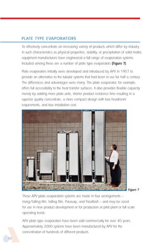
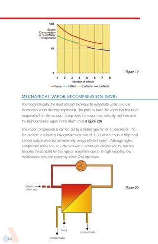
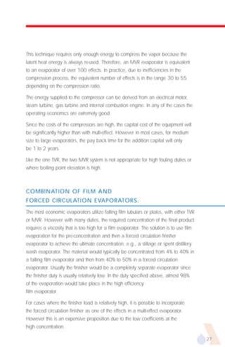
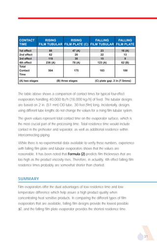
EHB-599


FOURTH EDITION


                 An Invensys company
C       O         N         T       E       N         T       S

    Introduction ...................................................3

    Evaporators...................................................4

    Evaporator Type Selection ............................20

    Configurations For Energy Conservation .......24

    Residence Time In Film Evaporation ..............28

    Designing For Energy Efficiency....................32

    Physical Properties .......................................34

    Mechanical Vapor
    Recompression Evaporators..........................36

    Evaporators For Industrial And
    Chemical Applications .................................42

    Waste Water Evaporators ............................47

    Tubular Evaporators
    For Sanitary Standards ................................50

    Evaporator Control ......................................52

    Preassembled Evaporators............................54

    The Production Of
    High Quality Juice Concentrates ...................55

    Engineering Conversions ..............................60

    Properties Of Saturated
    Steam Temperature Tables ............................61


2
I    N      T     R      O       D      U      C      T     I    O       N
As one of the most energy intensive processes used in the dairy, food and
chemical industries, it is essential that evaporation be approached from the
viewpoint of economical energy utilization as well as process effectiveness. This
can be done only if the equipment manufacturer is able to offer a full selection of
evaporation technology and systems developed to accommodate various product
characteristics, the percent of concentration required, and regional energy costs.

This Handbook describes the many types of evaporators and operating options
available through the experience and manufacturing capabilities of companies
within the APV Group.


                                                                                      3
E     V       A       P      O       R      A       T      O     R       S

    TYPES AND DESIGN

    In the evaporation process, concentration of a product is accomplished by boiling
    out a solvent, generally water. The recovered end product should have an
    optimum solids content consistent with desired product quality and operating
    economics. It is a unit operation that is used extensively in processing foods,
    chemicals, pharmaceuticals, fruit juices, dairy products, paper and pulp, and both
    malt and grain beverages. Also it is a unit operation which, with the possible
    exception of distillation, is the most energy intensive.

    While the design criteria for evaporators are the same regardless of the industry
    involved, two questions always exist: is this equipment best suited for the duty, and
    is the equipment arranged for the most efficient and economical use? As a result,
    many types of evaporators and many variations in processing techniques have
    been developed to take into account different product characteristics and
    operating parameters.


    TYPES OF EVAPORATORS

    The more common types of evaporators include:

              s   Batch pan                         s   Forced circulation
              s   Natural circulation               s   Wiped film
              s   Rising film tubular               s   Plate equivalents of
              s   Falling film tubular                  tubular evaporators

              s   Rising/falling film tubular


4
BATCH PAN

Next to natural solar evaporation, the batch pan (Figure 1) is one of the oldest
methods of concentration. It is somewhat outdated in today's technology, but is still
used in a few limited applications, such as the concentration of jams and jellies
where whole fruit is present and in processing some pharmaceutical products.
Up until the early 1960's, batch pan also enjoyed wide use in the concentration
of corn syrups.

With a batch pan evaporator, product residence time normally is many hours.
Therefore, it is essential to boil at low temperatures and high vacuum when a
heat sensitive or thermodegradable product is involved. The batch pan is either
jacketed or has internal coils or heaters. Heat transfer areas normally are quite
small due to vessel shapes, and heat transfer coefficients (HTC’s) tend to be low
under natural convection conditions. Low surface areas together with low HTC's
generally limit the evaporation capacity of such a system. Heat transfer is
improved by agitation within the vessel. In many cases, large temperature
differences cannot be used for fear of rapid fouling of the heat transfer surface.
Relatively low evaporation capacities, therefore, limit its use.


Figure 1
                                         CONDENSER


   STEAM


                                           CONDENSATE
                        PRODUCT


                                                                                        5
T     U       B      U       L     A       R
    E      V      A       P      O       R     A      T      O       R      S

    NATURAL CIRCULATION
                                                                                       TO CONDENSER
                                                                                        OR VACUUM


    Evaporation by natural circulation is
    achieved through the use of a
                                        STEAM
    short tube bundle within the
                                                                                   PRODUCT
    batch pan or by having an external                                               OUT


    shell and tube heater outside of the
    main vessel (Figure 2).
    The external heater has the advantage                                              FEED


    that its size is not dependent upon the
    size or shape of the vessel itself. As a
    result, larger evaporation capacities                                              Figure 2
    may be obtained. The most common
    application for this type of unit is as a reboiler at the base of a distillation column.


    RISING FILM TUBULAR
    Considered to be the first 'modern' evaporator used in the industry, the rising film
    unit dates back to the early 1900's. The rising film principle was developed
    commercially by using a vertical tube with steam condensing on its outside surface
    (Figure 3). Liquid on the inside of the tube is brought to a boil, with the vapor
    generated forming a core in the center of the tube. As the fluid moves up the tube,
    more vapor is formed resulting in a higher central core velocity that forces the
    remaining liquid to the tube wall. Higher vapor velocities, in turn, result in thinner
    and more rapidly moving liquid film. This provides
                                                                                  TO CONDENSER
    higher HTC's and shorter product residence time.                                OR VACUUM


    The development of the rising
    film principle was a giant
    step forward in the            STEAM


    evaporation field,
    particularly in product quality.
    In addition, higher HTC's
                                                                          PRODUCT
    resulted in reduced heat                                                OUT


    transfer area requirements                                            CONDENSATE

    and consequently, in a lower
                                        FEED
    initial capital investment.                                                         Figure 3

6
FALLING FILM TUBULAR

Following development of the rising film principle, it took almost half a century for
a falling film evaporation technique to be perfected (Figure 4). The main problem
was how to design an adequate system for the even distribution of liquid to each
of the tubes. For the rising film evaporator, distribution was easy since the bottom
bonnet of the calandria was always pumped full of liquid, thus allowing equal
flow to each tube.

While each manufacturer has its own technique, falling film distribution generally is
based around use of a perforated plate positioned above the top tube plate of the
calandria. Spreading of liquid to each tube is sometimes further enhanced by
generating flash vapor at this point. The falling film evaporator does have the
advantage that the film is 'going with gravity' instead of against it. This results in
a thinner, faster moving film and gives rise to an even shorter product contact time
and a further improvement in the value of HTC.

To establish a well-developed film, the rising film unit requires a driving film force,
typically a temperature difference of at least 25°F (14°C) across the heating
surface. In contrast, the falling film evaporator does not have a driving force
limitation–permitting a greater number of evaporator effects to be used within the
same overall operating limits. For
example, if steam is available at                                                Figure 4

220°F (104°C), then the last effect
boiling temperature is 120°F      STEAM

(49°C); the total available
∆T is equal to 100°F (55°C).
In this scenario a rising film      FEED

evaporator would be limited
                                                STEAM
to four effects, each with a ∆T
of 25°F (14°C). However,
using the falling film                                                            VACUUM

technique, it is feasible to have          CONDENSATE

as many as 10 or more effects.


                                                                       PRODUCT
                                                                         OUT

                                                                                            7
RISING/FALLING FILM TUBULAR

    The rising/falling film evaporator
                                                                                   Figure 5
    (Figure 5) has the advantages
    of the ease of liquid distribution
    of the rising film unit coupled
    with lower head room
    requirements. The tube bundle                STEAM


    is approximately half the height
    of either a rising or falling film
    evaporator, and the
                                         STEAM
    vapor/liquid separator is                                                       VACUUM


    positioned at the bottom of
    the calandria.                        FEED


                                                                         PRODUCT
    FORCED CIRCULATION                                                     OUT


    The forced circulation evaporator (Figure 6) was developed for processing liquors
    which are susceptible to scaling or crystallizing. Liquid is circulated at a high rate
    through the heat exchanger, boiling being prevented within the unit by virtue of a
    hydrostatic head maintained above the top tube plate. As the liquid enters the
    separator where the absolute pressure is slightly less than in the tube bundle, the
    liquid flashes to form a vapor.

    The main applications for a forced circulation evaporator are in the concentration
    of inversely soluble materials, crystallizing duties, and in the concentration of
    thermally degradable materials which result in the deposition of solids. In all cases,
    the temperature rise across the tube bundle is kept as low as possible, often as
    low as 3-5°F (2-3°C). This results in a recirculation ratio as high as 220 to 330
    lbs (100 to 150 Kg) of liquor per pound (kilogram) of water evaporated. These
    high recirculation rates result in high liquor velocities through the tube which help
    to minimize the build up of deposits or crystals along the heating surface. Forced
    circulation evaporators normally are more expensive than film evaporators
    because of the need for large bore circulating pipework and large recirculating
    pumps. Operating costs of such a unit also are considerably higher.


8
Figure 6                                          SEPARATOR               VAPOR
                                                                          OUTLET


                     LIQUOR HEAD
                 TO PREVENT BOILING
                 AT HEATING SURFACE                                 CONCENTRATED
                                                                       LIQUOR
                                                                       OUTLET


                  LOW TEMPERATURE        CALANDRIA
                    RISE ACROSS
                     CALANDRIA


                                                                            DILUTE
                                                                            LIQUOR
                                                                             INLET


                                                      CIRCULATION PUMP GIVING
                                                       HIGH LIQUOR VELOCITIES
                                                       OVER HEATING SURFACE


WIPED FILM

The wiped or agitated thin film evaporator has limited applications due to the high
cost and is confined mainly to the concentration of very viscous materials and the
stripping of solvents down to very low levels. Feed is introduced at the top of the
evaporator and is spread by wiper blades on to the vertical cylindrical surface
inside the unit. Evaporation of the solvent takes place as the thin film moves down
the evaporator wall. The heating medium normally is high pressure steam or oil.
A high temperature heating medium generally is necessary to obtain a reasonable
evaporation rate since the heat transfer surface available is relatively small as a
direct result of its cylindrical configuration.

The wiped film evaporator is satisfactory for its limited applications. However, in
addition to its small surface area, it also has the disadvantage of requiring moving
parts such as the wiper blades which, together with the bearings of the rotating
shaft, need periodic maintenance. Capital costs in terms of dollars per pound of
solvent evaporated also are very high.


                                                                                       9
PLATE TYPE EVAPORATORS

     To effectively concentrate an increasing variety of products which differ by industry
     in such characteristics as physical properties, stability, or precipitation of solid matter,
     equipment manufacturers have engineered a full range of evaporation systems.
     Included among these are a number of plate type evaporators (Figure 7).

     Plate evaporators initially were developed and introduced by APV in 1957 to
     provide an alternative to the tubular systems that had been in use for half a century.
     The differences and advantages were many. The plate evaporator, for example,
     offers full accessibility to the heat transfer surfaces. It also provides flexible capacity
     merely by adding more plate units, shorter product residence time resulting in a
     superior quality concentrate, a more compact design with low headroom
     requirements, and low installation cost.


                                                                                      Figure 7
     These APV plate evaporation systems are made in four arrangements –
     rising/falling film, falling film, Paravap, and Paraflash – and may be sized
     for use in new product development or for production at pilot plant or full scale
     operating levels.

     APV plate type evaporators have been sold commercially for over 40 years.
     Approximately 2000 systems have been manufactured by APV for the
     concentration of hundreds of different products.
10
APPLICATIONS

Although plate evaporators can be used on a broad range of products, the main
application has been with products that are heat sensitive and therefore benefit
from the high HTC’s and low residence time. Products that are being processed in
this evaporator include:

      s    Apple juice          s   Coffee               s   Pear juice
      s    Amino acids          s   Fruit purees         s   Pectin
      s    Beef broths          s   Gelatin              s   Pharmaceutical products
      s    Beet juice           s   Grape juice          s   Pineapple juice
      s    Betacyclodextrin     s   Lime juice           s   Skim milk
      s    Caragenan            s   Liquid egg           s   Sugars
      s    Cheese whey          s   Low alcohol beer     s   Vegetable juices
      s    Chicken broth        s   Mango juice          s   Whey protein
      s    Citrus juice         s   Orange juice         s   Whole milk


RISING/FALLING FILM PLATE

This is the original plate type evaporator. The principle of operation for the
rising/falling film plate evaporator (RFFPE) involves the use of a number of plate
packs or units, each consisting of two steam plates and two product plates. These
are hung in a frame which resembles that of a plate heat exchanger (Figure 8).
The first product passage is a rising pass and the second, a falling pass. The steam
plates, meanwhile, are arranged alternately between each product passage.


Figure 8
                   steam


condensate
                           vapor/liquid
                           product
  product feed
                                                                                       11
The product to be evaporated is fed through two parallel feed ports and is equally
     distributed to each of the rising film annuli. Normally, the feed liquor is introduced
     at a temperature slightly higher than the evaporation temperature in the plate
     annuli, and the ensuing flash distributes the feed liquor across the width of the
     plate. Rising film boiling occurs as heat is transferred from the adjacent steam
     passage with the vapors that are produced helping to generate a thin, rapidly
     moving turbulent liquid film.

     During operation, the vapor and partially concentrated liquid mixture rises to the
     top of the first product pass and transfers through a 'slot' above one of the
     adjacent steam passages. The mixture enters the falling film annulus where gravity
     further assists the film movement and completes the evaporation process. The rapid
     movement of the thin film is the key to producing low residence time within the
     evaporator as well as superior HTC’s. At the base of the falling film annulus, a
     rectangular duct connects all of the plate units and transfers the evaporated liquor
     and generated vapor into a separating device. A flow schematic for a two effect
     system is shown in (Figure 9).


                                                                                     Figure 9


12
The plate evaporator is designed to operate at pressures extending from
10 psig (1.7 barg) to full vacuum when using any number of effects. However,
the maximum pressure differential normally experienced between adjacent annuli
during single effect operation is 15 psi (1 bar). This, and the fact that the pressure
differential always is from the steam side to the product side, considerably reduce
design requirements for supporting the plates. The operating pressures are
equivalent to a water vapor saturation temperature range of 245°F (118°C)
downwards, and thus are compatible with the use of nitrile or butyl rubber gaskets
for sealing the plate pack.

Most rising/falling film plate evaporators are used for duties in the food, juice and
dairy industries where low residence time and a temperature lower than 195°F
(90°C) are essential for the production of quality concentrate. Also, increasing
number of plate evaporators are being operated successfully in both pharmaceutical
and chemical plants on such products as antibiotics and inorganic acids. These
evaporators are available as multi-effect and/or multi-stage systems to allow
relatively high concentration ratios to be carried out in a single pass, non-
recirculatory flow.

The rising/falling film plate evaporator should be given consideration for various
applications that:

    s   Require operating temperatures between 80-212°F (26 to 100°C)


    s   Have a capacity range of 1000-35,000 lbs/hr
        (450 to 16,000 kg/hr) water removal


    s   Have a need for future capacity increase since evaporator capabilities
        can be extended by adding plate units or by the addition of extra effects


    s   Require the evaporator to be installed in an area that has limited
        headroom as low as 13 ft (4m)


    s   Where product quality demands a low time/temperature relationship


    s   Where suspended solid level is low and feed can be passed
        through 50 mesh screen

                                                                                         13
A ‘Junior’ version of the
     evaporator (Figure 10) is
     available for pilot plant and test
     work and for low capacity
     production. If necessary, this
     can be in multi-effect/multi-stage
     arrangements.

                                                                                   Figure 10

     FALLING FILM PLATE

     Incorporating all the advantages of the original rising falling film plate evaporator
     system with the added benefits of shorter residence time and larger evaporation
     capabilities, the falling film plate evaporator has gained wide acceptance for the
     concentration of heat sensitive products. With its larger vapor ports, evaporation
     capacities are typically up to 60,000 lbs/hr (27,000 kg/hr).

     The falling film plate evaporator
                                                                                Figure 11
     consists of gasketed plate units
     (each with a product and a
     steam plate) compressed within
     a frame that is ducted to a
     separator. The number of plate
     units used is determined by the
     duty to be handled.

     One of the important innovations in this type of evaporator is the patented feed
     distribution system (Figure 11). Feed liquor first is introduced through an orifice
     (1) into a chamber (2) above the product plate where mild flashing occurs.
     This vapor/liquid mixture then passes through a single product transfer hole (3)
     into a flash chamber (4) which extends across the top of the adjacent steam plate.
     More flash vapor results as pressure is further reduced and the mixture passes in
     both directions into the falling film plate annulus through a row of small distribution
     holes (5). These assure an even film flow down the product plate surface where
     evaporation occurs. A unique feature is the ability to operate the system either in
     parallel or in series, giving a two-stage capability to each frame. This is
     particularly advantageous if product recirculation is not desirable.

14
Figure 12


In the two-stage method of operation, feed enters the left side of the evaporator
and passes down the left half of the product plate where it is heated by steam
coming from the steam sections. After the partially concentrated product is
discharged to the separator, it is pumped to the right side of the product plate
where concentration is completed. The final concentrate is extracted while
vapor is discharged to a subsequent evaporator effect or to a condenser. The
falling film plate is available in an extended form which provides up to 4000 ft2
(370m2) surface area in one frame. A flow schematic for a two effect system
(Figure 12) is shown above. An APV falling film plate evaporator in triple effect
mode (Figure 13) is shown below.


Figure 13. Plant representation. Triple-effect Falling Film Evaporator system followed
by a double-effect forced circulation tubular finisher. A distillation essence recovery
system was provided to recover the key essence components from the juice and in
particular the methyl anthranilate.

                                                                                          15
T H E            A P V             P A R A V A P
     E V A P O R A T I O N                                  S Y S T E M S

     THE PROCESS

     The APV Paravap evaporation system is designed for the evaporation of highly
     viscous liquids. The system is often used as a finishing evaporator to concentrate
     materials to high solids following a low solids multi-effect or MVR film evaporator.

     The main components of the system are a plate heat exchanger, vapor liquid
     separator, condenser and a series of pumps (Figure 14). It is designed to operate
     as a climbing film evaporator with the evaporation taking place in the plate
     passages. Compared with forced circulation evaporators, the pumping costs are
     significantly reduced.

     Under normal operating conditions the feed is introduced at the bottom of the
     plates. As the feed contacts the plate surface, which is heated by either steam
     or hot water, the feed starts to evaporate. The narrow gap and corrugations in
     the plate passages cause high turbulence and a resulting partial atomization of the
     fluid. This reduces the apparent liquid viscosity and generates considerably higher
     HTC’s than would occur in a shell and tube heat exchanger under similar
     conditions. It is particularly effective with non-Newtonian viscous liquids.


     Figure 14


16
A clear advantage when processing temperature sensitive products is gained with
a Paravap because most duties do not require liquid recirculation.

For most duties the conventional gasketed plate heat exchanger is specified.
However, for duties where the process fluid could attack the gasket, APV can offer
the welded plate pair exchanger which eliminates elastomer gaskets on the
process side.

The Paravap is usually operated in single effect mode although some systems are
operating with double effect.

Since most systems are not physically large, the equipment can often be fully
preassembled on a skid prior to shipment. Preassembly reduces installation time
and, in most cases, significantly lowers the overall project cost.

The Paravap evaporation system is particularly effective in processing the more
viscous products. Often the Paravap can be used in place of a wiped film or thin
film evaporator with a substantial reduction in cost. For duties where severe fouling
can occur on boiling heat transfer surfaces, the process should be performed in a
APV Paraflash system.

Some typical duties that are performed in a Paravap include:

   s   Concentration of sugar solutions to extremely high solids content.
       In one case a solids concentration of 98% was achieved.
   s   Removal of water from soaps.
   s   Finishing concentrator on certain fruit purees such as banana and apple.
   s   Concentration of high solids corn syrups.
   s   Removal of solvents from vegetable oils.
   s   Concentration of fabric softeners.
   s   Lignin solutions.
   s   High concentration gelatin.
   s   High concentration chicken broth.


                                                                                        17
T H E            A P V            P A R A F L A S H
     E V A P O R A T I O N                                  S Y S T E M S

     THE PROCESS

     The APV Paraflash evaporation system is designed for the evaporation of liquids
     containing high concentrations of solids. In particular, the system is used as a
     finishing evaporator to concentrate materials to high solids following a low solids
     multi-effect or MVR film evaporator.

     The main components of the system are a plate heat exchanger, vapor liquid
     separator, condenser and a series of pumps (Figure 15). It is designed to operate
     as a forced circulation evaporator with the evaporation being suppressed in the
     heating section by back pressure. This back pressure can be generated by a
     liquid head above the exchanger or by using an orifice piece or valve in the
     discharge from the evaporator. The evaporation then occurs as the liquid flashes
     in the entrance area to the separator.

     The suppression of boiling, together with the high circulation rate in the plate
     heat exchanger, result in less fouling than would occur in other types of
     evaporators. This increases the length of production runs between cleanings.
     In addition, the narrow gap and corrugations in the plate passages result in far
     higher heat transfer rates than would be obtained in shell and tube systems.


     Figure 15


18
For most duties the conventional gasketed plate heat exchanger is specified.
However for duties where the process fluid could attack the gasket, APV can offer
the welded plate pair exchanger which eliminates elastomer gaskets on the
process side.

The Paraflash can be used either as a single or multiple effect evaporator.

Since many systems are not physically large, the equipment can often be fully
preassembled on a skid prior to shipment. Preassembly reduces installation time
and, in most cases, significantly lowers the overall project cost.

Because of the large range of viscosities that can be handled in a Paraflash, this
form of evaporator can economically handle a wider range of duties than any
other evaporator. In particular, due to the high turbulence and corresponding high
shear rates, the Paraflash system is excellent at handling non-Newtonian fluids with
high suspended solids content.

Some typical duties that are performed in a Paraflash include:

   s   Concentration of wash water from water based paint plants to recover
       the paint and clean the water.
   s   Removal of water from dyestuffs prior to drying.
   s   Finishing concentrator on waste products from breweries and distilleries.
   s   Concentration of brewer’s yeast.
   s   Concentration of kaolin slurries prior to drying.
   s   Recovery of solvents in wastes from cleaning operations.
   s   Evaporation of solvents from pharmaceutical products.
   s   Crystallization of inorganic salts.
   s   Cheese whey.


                                                                                       19
E      V A          P     O         R       A       T       O   R
     T      Y     P     E            S       E       L       E   C   T   I    O        N
     The choice of an evaporator best suited to the duty on hand requires a number
     of steps. Typical rules of thumb for the initial selection are detailed below.
     A selection guide (Figure 16), based on viscosity and the fouling tendency
     of the product is shown below on next page.


     MODE OF EVAPORATION

     The user needs to select one or more of the various types of evaporator modes
     that were described in the previous section. To perform this selection, there are a
     number of ‘rules of thumb’ which can be applied.

     s   Falling film evaporation:
         – either plate or tubular, provides the highest heat transfer coefficients.
         – is usually the mode chosen if the product permits.
         – will usually be the most economic.
         – is not suitable for the evaporation of products with viscosities over 300cp.
         – is not suitable for products that foul heavily on heat transfer surfaces
           during boiling.
     s   Forced circulation evaporators:
         – can be operated up to viscosities of over 5,000cp.
         – will significantly reduce fouling.
         – are expensive; both capital and operating costs are high.
     s   Paravap evaporators:
         – are suitable for viscosities up to 10,000cp for low fouling duties.
         – are suitable for very high viscosities, i.e., over 20,000cp, usually the only
           suitable evaporation modes are the wiped film and thin film systems.


20
FILM EVAPORATORS–PLATE OR TUBULAR

s   Plate evaporators:
    – provide a gentle type of evaporation with low residence times and are
      often the choice for duties where thermal degradation of product can occur.
    – often provide enhanced quality of food products.
    – require low headroom and less expensive building and installation costs.
    – are easily accessed for cleaning.
    – provide added flexibility, since surface area can easily be added or removed.
s   Tubular evaporators:
    – are usually the choice for very large evaporators.
    – are usually the choice for evaporators operating above 25 psia (1.7 bar).
    – are better at handling large suspended solids.
    – require less floor space than plate evaporators.
    – have fewer gasket limitations.

FORCED CIRCULATION EVAPORATORS–PLATE OR TUBULAR

s   Plate systems will provide much higher HTC’s for all duties. With viscous products,
    the plate exhibits vastly improved performance compared with a tubular.
s   Tubular systems must be selected when there are particulates over 2mm diameter.

THE APV PARAVAP

s   For low fouling viscous products such as high brix sugar, the Paravap
    system is always the preferred solution.


                            High
                                                                           Wiped Film


                                           Paravap
                                                      Forced Circulation Plate
                               Viscosity


                                                            or Tubular


Figure 16                                               Recircu-
                                               Film      lated
This diagram shows a                                      Film
selection guide based on
the viscosity and fouling
tendency of the product.          Low                     Fouling                High

                                                                                          21
MATERIALS OF CONSTRUCTION

     The two parameters which control the selection of the material of construction are
     corrosion and ease of cleaning.

     All evaporators for hygienic duties must be capable of being frequently cleaned in
     place. In most cases, this means rinsing the equipment with water, followed by
     washing with caustic and then acid cleaning agents, and finally, a further rinsing
     with water. It is important, particularly with dairy and meat products, that the
     evaporator is completely cleaned of all deposits. The cleaning processes eliminate
     the use of carbon steel as the material of construction. Most hygienic evaporators
     are manufactured in either 304 or 316 stainless steel.

     Corrosion is often a major problem with chemical duties and some hygienic
     applications. A particular problem with evaporators is the range of concentration
     of solids in the process fluid, since the corrosive component will be concentrated
     as it passes through the evaporator. In some evaporators, the concentration range
     can be as high as 50 to 1. For example, waste water with a chloride content of
     40ppm in the feed would have 2000ppm in the product. While stainless steel
     would be acceptable for the initial stages of evaporation, a more corrosion
     resistant material would be required for the last one or two stages.

     Corrosion is also a major consideration in the selection of gasket materials. This
     is particularly important with plate evaporators with elastomeric gaskets sealing
     each plate. Many solvents such as chlorinated and aromatic compounds will
     severely attack the gaskets. A less obvious form of attack is by nitric acid. This is
     important since nitric acid can be present in some cleaning materials. While
     concentrations of about 1% up to 140°F (60°C) can be accepted, it is best to
     eliminate nitric acid from cleaning materials. Phosphoric and sulfamic acids are
     less aggressive to gaskets.


22
It is not the purpose of this handbook to provide guidelines for the selection of
materials of construction. The reader is referred to the APV Corrosion Handbook,
as well as the many publications issued by the material manufacturers.

Typical materials of construction for a number of evaporator applications are
shown below:

   PRODUCT                                MATERIAL OF CONSTRUCTION

   Most dairy and food products           304/316 stainless steel
   Most fruit juices                      316 stainless steel
   Sugar products                         Carbon steel /304/316
   Foods containing high salt (NaCl)      Titanium/Monel
                                          High alloy stainless steels
                                          Duplex stainless steels
   Caustic soda < 40%                     Stress relieved carbon steel
   Caustic soda high concentration        Nickel
   Hydrochloric acid                      Graphite/Rubber lined carbon steel


In some cases, the type of evaporator is controlled by the materials of construction.
For example a sulfuric acid evaporator, where the acid concentration can reach
50%, would utilize graphite tubular heat exchangers and non-metallic separators
and piping.


                                                                                        23
E V A P O R A T O R
     C O N F I G U R A T I O N S                                        F O R
     E N E R G Y                    C O N S E R V A T I O N
     Conservation of energy is one major parameter in the design of an evaporator
     system. The larger the evaporation duty, the more important it is to conserve energy.

     The following techniques are available:


     MULTI-EFFECT EVAPORATION

     Multi-effect evaporation uses the steam produced from evaporation in one effect
     to provide the heat to evaporate product in a second effect which is maintained
     at a lower pressure (Figure 17). In a two effect evaporator, it is possible to
     evaporate approximately 2 kgs of steam from the product for each kg of steam
     supply. As the number of effects is increased, the steam economy increases. On
     some large duties it is economically feasible to utilize as many as seven effects.

     Increasing the number of effects, for any particular duty, does increase the
     capital cost significantly and therefore each system must be carefully evaluated.
     In general, when the evaporation rate is above 3,000 lbs/h (1,350 kg/h),
     multi-effect evaporation should be considered.


     Figure 17


24
THERMO VAPOR RECOMPRESSION (TVR)

When steam is available at pressures in excess of 45 psig (3 barg) and
preferably over 100 psig (7 barg), it will often be possible to use thermo vapor
recompression. In this operation, a portion of the steam evaporated from the
product is recompressed by a steam jet venturi and returned to the steam chest of
the evaporator. A system of this type can provide a 2 to 1 economy or higher
depending on the product the steam pressure and the number of effects over
which TVR is applied.

TVR is a relatively inexpensive technique for improving the economy of evaporation.

TVR can also be used in conjunction with multi-effect to provide even larger
economies (Figure 18). Shown in (Figure 19) are the economies that can
be achieved.

Thermocompressors are somewhat inflexible and do not operate well outside the
design conditions. Therefore if the product is known to foul severely, so that the
heat transfer coefficient is significantly reduced, it is best not to use TVR. The
number of degrees of compression is too small for materials that have high
boiling point elevation.


Figure 18


                                                                                      25
Figure 19


     MECHANICAL VAPOR RECOMPRESSION (MVR)

     Thermodynamically, the most efficient technique to evaporate water is to use
     mechanical vapor thermocompression. This process takes the vapor that has been
     evaporated from the product, compresses the vapor mechanically and then uses
     the higher pressure vapor in the steam chest (Figure 20).

     The vapor compression is carried out by a radial type fan or a compressor. The
     fan provides a relatively low compression ratio of 1:30 which results in high heat
     transfer surface area but an extremely energy efficient system. Although higher
     compression ratios can be achieved with a centrifugal compressor, the fan has
     become the standard for this type of equipment due to its high reliability, low
     maintenance cost and generally lower RPM operation.


                                                                               Figure 20


26
This technique requires only enough energy to compress the vapor because the
latent heat energy is always re-used. Therefore, an MVR evaporator is equivalent
to an evaporator of over 100 effects. In practice, due to inefficiencies in the
compression process, the equivalent number of effects is in the range 30 to 55
depending on the compression ratio.

The energy supplied to the compressor can be derived from an electrical motor,
steam turbine, gas turbine and internal combustion engine. In any of the cases the
operating economics are extremely good.

Since the costs of the compressors are high, the capital cost of the equipment will
be significantly higher than with multi-effect. However in most cases, for medium
size to large evaporators, the pay back time for the addition capital will only
be 1 to 2 years.

Like the one TVR, the two MVR system is not appropriate for high fouling duties or
where boiling point elevation is high.


COMBINATION OF FILM AND
FORCED CIRCULATION EVAPORATORS.

The most economic evaporators utilize falling film tubulars or plates, with either TVR
or MVR. However with many duties, the required concentration of the final product
requires a viscosity that is too high for a film evaporator. The solution is to use film
evaporation for the pre-concentration and then a forced circulation finisher
evaporator to achieve the ultimate concentration; e.g., a stillage or spent distillery
wash evaporator. The material would typically be concentrated from 4% to 40% in
a falling film evaporator and then from 40% to 50% in a forced circulation
evaporator. Usually the finisher would be a completely separate evaporator since
the finisher duty is usually relatively low. In the duty specified above, almost 98%
of the evaporation would take place in the high efficiency
film evaporator.

For cases where the finisher load is relatively high, it is possible to incorporate
the forced circulation finisher as one of the effects in a multi-effect evaporator.
However this is an expensive proposition due to the low coefficients at the
high concentration.

                                                                                           27
R E S I D E N C E                            T I M E              I N
     F I L M             E V A P O R A T I O N
     Since many pharmaceutical, food and dairy products are extremely heat
     sensitive, optimum quality is obtained when processing times and temperatures
     are kept as low as possible during concentration of the products. The most critical
     portion in the process occurs during the brief time that the product is in contact
     with a heat transfer surface which is hotter than the product itself. To protect
     against possible thermal degradation, the time/temperature relationship therefore
     must be considered in selecting the type and operating principle of the evaporator
     to be used.

     For this heat sensitive type of application, film evaporators have been found to
     be ideal for two reasons. First, the product forms a thin film only on the heat
     transfer surface rather than occupying the entire volume, greatly reducing
     residence time within the heat exchanger. Second, a film evaporator can operate
     with as low as 6°F (3.5°C) steam-to-product temperature difference. With both the
     product and heating surfaces close to the same temperature, localized hot spots
     are minimized.

     As previously described, there are rising film and falling film evaporators as well
     as combination rising/falling film designs. Both tubular and plate configurations
     are available.


     COMPARISON OF RISING FILM
     AND FALLING FILM EVAPORATORS

     In a rising film design, liquid feed enters the bottom of the heat exchanger and
     when evaporation begins, vapor bubbles are formed. As the product continues up
     either the tubular or plate channels and the evaporation process continues, vapor
     occupies an increasing amount of the channel. Eventually, the entire center of the
     is filled with vapor while the liquid forms a film on the heat transfer surface.


28
The effect of gravity on a rising film evaporator is twofold. It acts to keep the
liquid from rising in the channel. Further, the weight of the liquid and vapor in
the channel pressurizes the fluid at the bottom and with the increased pressure
comes an increase in the boiling point. A rising film evaporator therefore requires
a larger minimum ∆T than a falling film unit.

The majority of the liquid residence time occurs in the lower portion of the channel
before there is sufficient vapor to form a film. If the liquid is not preheated above
the boiling point, there will be no vapor. And since a liquid pool will fill the entire
area, the residence time will increase.

As liquid enters the top of a falling film evaporator, a liquid film formed by gravity
flows down the heat transfer surface. During evaporation, vapor fills the center of
the channel and as the momentum of the vapor accelerates the downward
movement, the film becomes thinner. Since the vapor is working with gravity, a
falling film evaporator produces thinner films and shorter residence times than a
rising film evaporator for any given set of conditions.


TUBULAR AND PLATE FILM EVAPORATORS

When compared to tubular designs, plate evaporators offer improved residence
time since they carry less volume within the heat exchanger. In addition, the height
of a plate evaporator is less than that of a tubular system.


                                                                                          29
ESTIMATING RESIDENCE TIME

     It is difficult to estimate the residence time in film evaporators, especially rising film
     units. Correlations, however, are available to estimate the volume of the channel
     occupied by liquid. Formula (1) is recommended for vacuum systems.

     For falling film evaporators, the film thickness without vapor shearing can be
     calculated by Formula (2).

     Since the film is thin, this can be converted to liquid volume fraction in a tubular
     evaporator by Formula (3).

     For a falling film plate evaporator, Formula (4) is used. As liquid travels down the plate
     and evaporation starts, vapors will accelerate the liquid. To account for this action, the
     rising film correlation is used when the film thickness falls below that of a falling film
     evaporator. In practice, the film thickness may be less than estimated by either method
     because gravity and vapor momentum will act on the fluid at the same time.

     Once the volume fraction is known, the liquid residence time is calculated by
     formula (5). In order to account for changing liquid and vapor rates, the volume
     fraction is calculated at several intervals along the channel length. Evaporation is
     assumed to be constant along with channel length except for flash due to high
     feed temperature.


      SYMBOLS                                         FORMULAS

      A       cross sectional area                                                        1
      d       tube diameter                           (1)   RL = 1 –
                                                                              (           ) ( 2ρρ )
                                                                                                       .5
                                                                         1+       1–y              V
      g       gravitational constant                                               y               L

      L       tube length
      m       film thickness
                                                                           3Γµ
                                                                   [                      ]
                                                                                          1
      RL      liquid volume fraction                                                          /3
                                                      (2)   m=
                                                                       g ρL ( ρL – ρv )
      qL      liquid rate
      t       time
      Γ       liquid wetting rate
      ρL      liquid density                                           4m
      ρV      vapor density
                                                      (3)   RL =
                                                                        d
      µ       liquid viscosity
      y       local weight fraction of vapor                           2m
                                                      (4)   RL =
      References                                                        Z
      a) HTRI report, BT-2, pg. 7 (May
      1978)                                                        RL AL
                                                      (5)   t=
                                                                    qL
      b) Perry's Chemical Engineer's


30
CONTACT              RISING       RISING        FALLING     FALLING
TIME             FILM TUBULAR FILM PLATE (C) FILM TUBULAR FILM PLATE

1st effect             88                  47 (A)              23              16 (A)
2nd effect             62                    20                22                13
3rd effect             118                   30                15                 9
4th effect           236 (A)               78 (A)            123 (A)           62 (B)
Total
Contact                504                  175                183              100
Time

(A) two stages                 (B) three stages            (C) plate gap .3 in (7.5mms)


The table above shows a comparison of contact times for typical four-effect
evaporators handling 40,000 lb/h (18,000 kg/h) of feed. The tubular designs
are based on 2 in. (51 mm) OD tube, 30 feet (9m) long. Incidentally, designs
using different tube lengths do not change the values for a rising film tubular system.

The given values represent total contact time on the evaporator surface, which is
the most crucial part of the processing time. Total residence time would include
contact in the preheater and separator, as well as additional residence within
interconnecting piping.

While there is no experimental data available to verify these numbers, experience
with falling film plate and tubular evaporators shows that the values are
reasonable. It has been noted that Formula (2) predicts film thicknesses that are
too high as the product viscosity rises. Therefore, in actuality, 4th effect falling film
residence times probably are somewhat shorter than charted.


SUMMARY

Film evaporators offer the dual advantages of low residence time and low
temperature difference which help assure a high product quality when
concentrating heat sensitive products. In comparing the different types of film
evaporators that are available, falling film designs provide the lowest possible
∆T, and the falling film plate evaporator provides the shortest residence time.


                                                                                            31
D E S I G N I N G                                   F O R
     E N E R G Y                          E F F I C I E N C Y
     Although the concentration of liquids by evaporation is an energy intensive
     process, there are many techniques available, as detailed in previous sections, to
     reduce the energy costs. However, increased energy efficiency can only be
     achieved by additional capital costs. As a general rule, the larger the system, the
     more it will pay back to increase the thermal efficiency of the evaporator.

     The problem is to select the correct technique for each application.

     The main factors that will affect the selection of the technique are detailed below.


     EVAPORATION RATE

     The higher the capacity of the evaporator, the more the designer can justify
     complex and expensive evaporation systems in order to provide high
     energy efficiency.

     For evaporator design purposes, the capacity is defined as the evaporation rate
     per hour. However, in some applications such as seasonal fruit juice processors,
     the equipment is only operated for part of the year. This means that an expensive
     evaporator is idle for part of the year. The economic calculation has to include
     annual operating hours.

     For low capacities the designer is less concerned about energy efficiency. If the
     evaporation rate is below 2,200 lb/h (1000 kg/h), it is difficult to justify multi-
     effect evaporation. Usually a single-effect evaporator, often with thermo vapor
     recompression (TVR), is the system of choice at this capacity.

     In many cases, mechanical vapor recompression (MVR) is the most efficient
     evaporator. However, these systems operate at a low temperature difference,
     which results in high heat transfer area. Also MVR requires either a centrifugal
     compressor or a high pressure fan which are expensive equipment items.
     These cannot usually be justified for low capacity evaporators.


32
STEAM/ELECTRICITY COSTS

For medium to large duties, a selection has to be made between multi-effect and
MVR. A critical parameter that will affect this selection are steam costs relative to
electricity costs. Providing process conditions are favorable, MVR evaporation will
be more economic, particularly in areas where the electricity cost is low, such as
localities around major hydro generating plants. However if low cost steam is
available, even at pressures as low as atmospheric, then multi-effect evaporation
will be usually more economic due to the lower capital cost.


STEAM PRESSURE

The availability of steam at a medium pressure of about 100 psig (7 barg),
permits the efficient use of TVR either on a single or multi-effect evaporator. TVR
can be applied across one, two or even three effects. This is the simplest and
least costly technique for enhancing evaporator efficiency. The effectiveness
declines significantly as the available steam pressure is reduced.


MATERIAL OF CONSTRUCTION

The majority of evaporators are made in 304 or 316 stainless steel. However
there are occasions that much more expensive materials of construction are
required, such as 904L, 2205, nickel, Hastelloy C, titanium and even graphite.

These expensive materials skew the economic balance, with the capital cost
becoming more significant in the equation. Typically MVR would become
less economic as the material cost increases, due to the size of the heat
exchangers required.


                                                                                        33
P H Y S I C A L                          P R O P E R T I E S
     There are a number of physical properties that can severely influence the selection
     of an evaporator.


     BOILING POINT ELEVATION

     A boiling point elevation of over 5°F (3°C) essentially eliminates MVR
     evaporators from consideration. This can be partially circumvented by using MVR as
     a pre concentrator. Once the concentration is sufficient to produce significant boiling
     point elevation, the final evaporation would be performed in a steam driven finisher.


     PRODUCT VISCOSITY

     High product viscosity of over 300 to 400cp usually eliminates falling film
     evaporators in favor of forced circulation. Forced circulation requires a higher
     temperature difference, which eliminates MVR. TVR is used on some duties.


     PRODUCT FOULING

     Both MVR and TVR are not particularly suitable for duties where severe fouling of
     heat transfer surfaces occurs over a short time period. The performance of these
     evaporators will fall off more rapidly than with a multi-effect system. Forced
     circulation evaporators with suppressed boiling usually perform better with high
     fouling than film evaporators.


     TEMPERATURE SENSITIVE PRODUCTS
     Many products, particularly in the food industry, are prone to degradation at
     elevated temperatures. The effect is usually made worse by extended residence time.
     This problem limits the temperature range for multi-effect systems. For example on
     a milk evaporator, the temperature is limited to a maximum of 160°F (71°C).
     Since a typical minimum boiling temperature is 120°F (49°C), there is a limited
     temperature difference to perform the evaporation. This type of duty is suitable for
     MVR since the evaporation occurs at essentially the same temperature. Although a
     lower operating temperature increases the size of the major equipment, MVR is the
     most economic solution for large capacity dairy evaporators.

34
In many cases the selection of the energy conservation technique is obvious.
However, for many applications it is necessary to evaluate a number of techniques
in detail before a decision can be made.

The following case study illustrates the various options to save energy using
different techniques.

The duty is to concentrate skim milk from 8% solids to 48% by evaporation.
The feed rate is 100,000 lb/h (45,500 kg/h). The data shown in the table
below summarizes the performance and costs for a straight 5 effect evaporator,
a 5 effect evaporator with TVR across 3 effects, and a mechanical vapor
recompression evaporator.

No pasteurizer is included in this cost comparison.

Annual operating costs are based on 7,000 h/year of operation, with a steam
cost of $5.50/1000 lb (454 kg) and electricity at $0.068/kwh.

                                 5 EFFECT      5 EFFECT WITH TVR                MVR
 Evaporation            lb/h          83,000                    83,000        83,000
                        kg/h          37,900                    37,900        37,900
 Steam Consumed         lb/h          17,000                    11,000             0
                        kg/h           7,700                     5,000             0
 Absorbed power         kw                70                        60           560
 Annual costs
 Steam                             $654,500                   $423,500             0
 Electricity                        $33,300                    $28,560      $266,560
 Total                             $687,800                   $452,060      $266,560
 Capital costs
 Equipment                        $2,200,000                $2,600,000    $2,700,000


The examples illustrate that with a higher capital investment, it is possible to
significantly reduce the operating costs of the equipment. However the most
economic selection is controlled by the steam and electricity prices. For example,
if the dairy is located alongside an electric co-generation plant, the steam cost
would be reduced considerably lower, and a steam heated evaporator would be
the most economic.

A less important, but still significant factor, is the cost of cooling water. An MVR
evaporator requires virtually no cooling water. On a steam heated system the
cooling water requirement is about 6 US gallons per lb (.05 m3 per kg) of
steam applied.
                                                                                       35
M E C H A N I C A L                                   V A P O R
     R E C O M P R E S S I O N
     E V A P O R A T O R S
     Mechanical vapor recompression (MVR) evaporation provides an extremely
     energy efficient technique for the concentration of solids in water. Usually the
     capital cost of an MVR system is higher than a comparable steam driven
     evaporator. However, as the capacity of the system increases the relative cost
     difference decreases. Although MVR evaporators are seldom chosen for small
     duties, the concept is often used for medium to large capacity evaporators.


     MVR DEFINED

     The basic principle of MVR is to remove the steam that is evaporated from the
     product, compress it in a mechanical device, and use the higher pressure steam,
     which has a corresponding higher saturation temperature, to provide the heating
     medium for the evaporation (Figure 21). No steam input is required once the
     system is operating. The small difference in enthalpy between the vapors on the
     condensing and boiling sides is the theoretical energy required to perform the
     evaporation. Essentially, the process re-uses the latent heat of the vapors. The
     theoretical thermal efficiency of MVR can exceed that of a 100 effect evaporator,
     although there are a number of practical limitations, such as
     compressor and motor efficiencies which lower
                                                                                  Figure 21
     the achievable efficiency.

     The mechanical device
     can be a centrifugal
     compressor for applications
     with high compression ratios,
     or a fan for lower compression
     ratios. For either device, the
     drive can be an electric motor,
     steam turbine, internal
     combustion engine or
     gas turbine.

36
C
                               1164.6
                                                                                                               T=243°F

                                                     SUPERHEAT


                                                                                            I
                                                                                          PS
                                                     AVAILABLE FOR


                                                                                        2
                                                                                      7.
                                                     GENERATING


                                                                                    -1
                                                     EXCESS VAPOR                 B


                                                                                                                 IA
                                                                                  T
                                        COMPRESSOR


                                                                                EA


                                                                                 N
                                                     11.2 BTU/LB


                                                                                                               PS
            H-ENTROPY BTU/LB


                                                                            SSIO
                                                                             RH


                                                                           UAL


                                                                                                              .7
                                        INPUT 14.1


                                                                COMPRESSION
                                                                           PE


                                                                                                            14
                                        ENERGY


                                                                       PRE
                                                                         SU
                                        BTU/LB


                                                                      ACT
                                                                       DE


                                                                   IDEAL


                                                                   COM
                                                            D                                                  T=220°F
                               1153.4


                                                                                                               T=212°F
                               1150.5
                                        ENTHALPY                              A
                                        DIFFERENCE                                    SA             SUPERHEATED
                                        AT CONDENSING                                   TU              VAPOR
                                                                                           RA
                                        TEMPERATURES                                         TE
                                        2.9 BTU/LB                                             D
                                                                                                     VA
                                                                                                        POR

                                                                                                    VAPOR
                                                                                                    LIQUID
                                                                                                    MIXTURE
Figure 22
                                                           1.7442            1.7568        1.7596

                                                             S-ENTROPY BTU/LB°F


THERMODYNAMICS OF MVR

The process is best explained by reference to the Mollier–enthalpy/entropy
diagram for steam (Figure 22).

The vapor evaporated from the product is represented on the Mollier diagram
at point A. The actual values in US and metric units are presented on
Table 1a and 1b. The vapor enters the compressor at point A. The vapor is then
compressed to the higher pressure, at constant entropy at point B. The compressor,
which in this case is a fan, has inefficiencies which results in an increase in
entropy above that of the entropy at inlet. This is represented by point C. Vapor
at point C is at the required pressure for the steam jacket of the condenser.
However, it is superheated and must be cooled in order to condense in the
evaporator. This cooling can be performed on the heat transfer surface of the
evaporator. However, since desuperheating HTC’s are usually low, the
desuperheating is usually performed by the introduction of a spray of condensate
into the vapor duct. This condensate vaporizes as the vapor is cooled back to the
saturation temperature, and generates more vapor. This condition is represented by
point D. At this point most of the vapor is condensed in the evaporator. However,
there is an excess of vapor, which is required for heat loss and/or preheat duties.
Any balance is condensed or vented.


                                                                                                                         37
PROPERTIES OF WATER VAPOR

      Pressure-PSIA                         14.7           17.2                17.2
      State                             Saturated        Saturated         Superheated
      Temperature °F                       212              220                243
      H-Enthalpy Vapor BTU/LB            1150.5           1153.4             1164.6
      Latent Heat BTU/LB                  970.3            965.2                —
      H-Enthalpy Liquid BTU/LB            180.2            188.2                —
      S-Enthalpy BTU/LB °F               1.7568           1.7442             1.7596

     Table 1a. Properties of Water Vapor.


                              PROPERTIES OF WATER VAPOR
      Pressure-BAR                           1             1.17                1.17
      State                             Saturated        Saturated         Superheated
      Temperature °C                       100              104                117
      H-Enthalpy Vapor Kcals/Kg           639.1            640.8              647.0
      Latent Heat Kcals/Kg                539.0            536.2                —
      H-Enthalpy Liquid Kcals/Kg          100.1            104.6                —
      S-Enthalpy Kcals/Kg °C             1.7568           1.7442             1.7596

     Table 1b. Properties of Water Vapor.


     In this example, the heat required to evaporate the water is 970.3 Btu
     (539.0 Kcals). However the compressor input is only 14.1 Btu (7.8 Kcals), with
     motor and gearbox losses increasing this to 14.7 Btu (8.16). The equivalent
     economy is 66 to 1.

     It should be noted that pressure losses through the evaporator ducting, calandria
     and separator must be absorbed. This can be achieved by either a higher boost
     from the compressor at a higher power, or by accepting a lower temperature
     difference and increasing the surface area of the calandria.


38
TYPES OF COMPRESSION EQUIPMENT

To a large extent, the development of this technology has been guided by the
capabilities of the various types of compressors. The key to the design is the
temperature difference that is available for the evaporator. Table 2 shows the
temperature difference for various compression ratios at two different boiling
temperatures. It is this temperature difference that is available as the driving force
for evaporator, less a small amount required in the form of lost pressure around the
system. The original MVR systems used compressors with compression ratios of
about 1.4, which limited the available temperature difference to 13 to 18°F (7 to
10°C). This limits the MVR to single effect operation. More advanced centrifugal
compressors were developed in the 1970s, which provided compression ratios of
approximately 2. This provided a much higher temperature difference, which
allowed operation with 2 and 3 effects. This reduces the flow to the compressor
and increases the operating efficiency.

 COMPRESSION RATIO              SATURATED ∆T AT BOILING TEMPERATURES
                                    130°F       55°C        212°F        100°C
           1.2                         6.9         3.8             9.3      5.2
           1.4                        12.9         7.2            17.5      9.7
           1.6                        18.2        10.1            24.7     13.7
           1.8                        23.0        12.8            31.2     17.3
           2.0                        27.3        15.1            37.2     20.7

Table 2. Saturated ∆T at Various Compression Ratios, °F and °C.


A number of evaporators were built with the higher compression systems in multi-
effect mode. Unfortunately, the reliability of the compressors became a problem.
Because the compressor operates at high speed, it has to be protected from
impingement of water droplets. This usually requires a mist eliminator in the
separator, followed by a superheater. Any solids carryover will have a detrimental
effect on the compressor. In addition, the designer must take care to prevent
unstable compressor operation (surging). While the majority of the compressors
functioned well, there were a few catastrophic compressor failures. These failures
caused engineers to review alternative equipment.

The answer to the compressor problem was to use a fan. This equipment operates
at a lower speed and is less vulnerable to damage from droplets. Fans are also
far less likely to surge. When operated with a variable frequency drive, the fans
                                                                                         39
provide far greater flexibility than compressors. The only disadvantage to the fan is
     that compression ratios are limited to about 1.45. This results in a low available
     temperature difference and therefore a high heat transfer area. However, the
     energy efficiency of such systems is very high with the equivalent of 55 effects
     achievable for many duties.


     POWER REQUIREMENTS

     The compressor power requirements to evaporate 1000 lb/h (454 kg/h) of
     steam at various compression ratios and temperatures are shown in
     Tables 3a and 3b. Similar data for fans are shown in Tables 4a and 4b.
     These data correspond quite well with installed MVR systems.

     A more detailed comparison between three actual systems is shown in Table 5. The more
     energy efficient system is the single effect fan with a low compression ratio. However, the
     low temperature difference will result in high heat transfer area in the calandria. In most
     cases the added capital cost will be justified by lower operating costs.

                                         COMPRESSORS
     Boiling Temp 130°F                Boiling Temp 170°F                 Boiling Temp 212°F
     CR        ∆T        kw             CR       ∆T       kw             CR        ∆T      kw
     1.3      10.00      7.0            1.3     11.65      7.5           1.3     13.53      7.9
     1.4      12.91      9.1            1.4     15.03      9.7           1.4     17.47     10.3
     1.6      18.21     12.9            1.6     21.23     13.8           1.6     24.69     14.7
     1.8      22.98     16.5            1.8     26.81     20.0           1.8     31.20     18.7
     2.0      27.31     19.8            2.0     31.89     21.1           2.0     37.16     22.5
     2.2      31.30     22.9            2.2     36.57     27.2           2.2     41.31     24.9

     Table 3a. Power Vs ∆T for Centrifugal Compressors Based on 1000 lb/h of Steam Evaporated.


                                         COMPRESSORS
     Boiling Temp 55°C                  Boiling Temp 77°C               Boiling Temp 100°C
     CR        ∆T        kw             CR       ∆T       kw             CR        ∆T      kw
     1.3       5.55     15.4            1.3      6.47     16.4           1.3      7.51     17.5
     1.4       7.17     20.0            1.4      8.35     21.3           1.4      9.71     22.7
     1.6      10.11     28.5            1.6     11.79     30.4           1.6     13.71     32.4
     1.8      12.77     36.3            1.8     14.89     38.7           1.8     17.33     41.3
     2.0      15.17     43.5            2.0     17.71     46.4           2.0     20.64     49.4
     2.2      17.39     50.3            2.2     20.37     53.6           2.2     22.95     57.1

     Table 3b. Power Vs ∆T for Centrifugal Compressors Based on 454 kg/h of Steam Evaporated.


40
SMALL MVR EVAPORATORS

For small systems, rotary blowers were occasionally specified in an attempt to
make MVR economic at evaporation capacities less than 15,000 lb/h
(7000 kg/h). While there were cost savings, there were also reliability problems
with this equipment for this particular application. The conclusion remained that for
small systems, it is usually best to use steam driven evaporators.

                                           FANS
 Boiling Temp 130°F              Boiling Temp 170°F                  Boiling Temp 212°F
 CR      ∆T          kw          CR          ∆T     kw            CR          ∆T      kw
 1.1    3.59        2.22         1.1        4.17   2.38           1.1        4.85    2.54
 1.2    6.91        4.31         1.2        8.04   4.60           1.2        9.34    4.92
 1.3    10.00       6.28         1.3       11.65   6.71           1.3       13.53    7.15
Table 4a. Power Vs ∆T for Fans Based on 1000 lb/h of Steam Evaporated.


                                           FANS
 Boiling Temp 55°C               Boiling Temp 77°C                Boiling Temp 100°C
 CR       ∆T        kw           CR         ∆T     kw             CR         ∆T          kw
 1.1     1.99      4.90          1.1       2.32     5.22             1.1     2.69    5.58
 1.2     3.84      9.49          1.2       4.47    10.12             1.2     5.19    10.81
 1.3     5.56     13.81          1.3       6.47    14.75             1.3     7.52    15.73

Table 4b. Power Vs ∆T for Fans Based on 454 kg/h of Steam Evaporated.


                           SINGLE EFFECT DOUBLE EFFECT TRIPLE EFFECT
                                FAN       CENTRIFUGAL  CENTRIFUGAL
 Compression Ratio                 1.2                    1.6                    2.0
 Total ∆T Available           6.9°F (3.8°C)        18.2°F (10.1°C)         27.3°F (15.2°C)
 Vapor to Compressor           60,000 lb/h           30,000 lb/h             20,000 lb/h
                              (27,300 kg/h)         (13,650 kg/h)           (9,090 kg/h)
 Total Power Kw                    280                   390                     400
 Equivalent Steam                870 lb/h              1315 lb/h              1347 lb/h
                                (395 kg/h)            (600 kg/h)             (612 kg/h)
 Equivalent
 Steam Economy                      69                    45.6                   44.5
 Average ∆T Per Effect            6.9°F                  9.1°F                  9.1°F
 Before Losses                   (3.8°C)                (5.1°C)                (5.1°C)

 NOTE: In this example, the fan horsepower is lower than either of the centrifugal
       designs, but the lower ∆T required the greater the surface area.

Table 5. Comparison of Typical MVR Designs – Approximate boiling temperature –
130°F (55°C) evaporation rate–60,000 lb/hr (27,000 kg/h).

                                                                                              41
E V A P O R A T O R S                              F O R
     I N D U S T R I A L                           A N D
     C H E M I C A L                        A P P L I C A T I O N S
     The APV range of evaporators covers many duties in the concentration of
     chemicals and industrial products, with both film and forced circulation systems
     being available as required.

     Film evaporators are used when there is little or no risk of fouling of the heating
     surfaces. Where such a risk is present, forced circulation units are recommended.
     All designs are suitable for multi-effect evaporation. At low concentrations,
     mechanical vapor recompression can be employed.

     After selecting the type of evaporator required for a particular duty, the most
     important factor is the selection of the materials of construction. Many duties
     can be handled with 316 stainless steel. For some applications where chloride
     ions are present, higher grades of stainless steel, such as 904L, can be an
     economic selection.

     Certain products are so corrosive that they cannot be processed in
                                                                                     Figure 23
     conventional metals. As an example,
     concentration of a sulfuric acid solution
     of up to 50% at 302°F (150°C)
     would call for main plant items of
     filament wound fiberglass reinforced
     epoxy resin, and heating and cooling
     surfaces of impervious graphite.
     If the sulfuric acid solution is between
     50 and 80% with temperatures up to
     230°F (110°C), main plant items should
     be lead-lined mild steel protected with
     refractories or carbon tiles. Heat transfer
     surfaces again would be of impervious
     graphite. A typical system (Figure 23)
     is shown here. It should be noted that APV
     does not market non-metallic evaporators.

42
TITANIUM SULFATE

The production of titanium dioxide pigments involves reaction between sulfuric
acid and the ore which contains iron, titanium sulfate and other compounds.

After pretreatment, which includes the crystallization of iron as ferrous sulfate,
the liquor is heated and hydrolyzed to precipitate titanium dioxide. Prior to this
operation, the concentration of liquor has to be adjusted by the evaporation of
water. It is essential that this process takes place in an evaporator with short
heat contact times in order to avoid the premature hydrolysis that occurs with
prolonged heating, which subsequently causes fouling of the heat surface and
blockage of the tubes. Although the liquor contains a high proportion of sulfuric
acid, the presence of other ions in solution may inhibit corrosion, so that copper
often can be used for heat transfer surfaces. Titanium is another material used
for this application.

Generally, single or multiple effect rising film evaporators are used for this duty, the
number of effects being determined by throughput and by assessing the cost of
operation against the increase in capital required for additional equipment.

In some cases, it is economically attractive to operate the evaporator as a single
effect unit at atmospheric pressure using the vapor given off for preheating. The
liquor is discharged at a temperature in excess of 212°F (100°C), reducing the
subsequent thermal load at the hydrolysis stage.


PHOSPHORIC ACID

Phosphoric acid can be produced by the digestion of phosphate rock (calcium
phosphate and fluoride among others) in sulfuric acid, better known as the "wet
process" acid. Since calcium sulfate normally is a constituent, scaling must be
considered. Phosphate rock varies in composition, and in general, periodic
cleaning is required even in forced circulation evaporators.

Sulfuric acid plants often are located along coastal areas, and a further problem
in concentration stems from the use of sea water in the direct contact condensers.
With silica present in the phosphate rock, fluorine reacts to form hydrofluorosilicic
acid (H2SiF6) which in turn, forms a sodium salt from the NaCl. Sodium fluorosilicic
can block the condensers.

                                                                                           43
AMMONIUM NITRATES

     This material has several significant properties:

        s   Low viscosity which allows it to be concentrated to
            99+% w/w when it is prilled.
        s   Above 95%, ammonium nitrate has an extremely high boiling point
            elevation which requires exceedingly high steam pressures for heating.
            This presents considerable mechanical problems.
        s   Any organic impurity has the potential for explosion, such that extra low
            carbon stainless steels must be used for heat transfer surfaces, and the use
            of mineral oils for heating is excluded.

     The type of evaporator best suited for ammonium nitrate depends upon the
     initial and final concentrations. For the range below 70% and up to 80-85%,
     rising film multi-effect evaporator units have been used successfully. For 80-96%
     concentrations, conventional falling film systems have been employed. Above
     96%, however, falling film with a heated air sweep would be used due to
     partial pressure conditions. In areas of relatively low humidity, 99+% water
     to water can be achieved.


     AMMONIUM SULFATE

     Ammonium sulfate is used in battery spacer plate production and also has
     been crystallized. In this process, small but regular sized crystals are mixed
     with a PVC type plastic and dissolved out of the final sheet which then is used
     as spacer plate. Stainless steel has been successfully employed as the material
     of construction.


     BARIUM SALTS

     The production of barium salt involves the use of sodium sulfide, a material
     which closely resembles caustic soda in both physical and corrosive properties.
     It generally is concentrated in a high vacuum crystallizer for the production of
     barium hydroxide with rubber lined mild steel being used as the material of
     construction due to corrosion considerations. With liquid temperatures below
     72°F, two hydrates--–mono and penta–can be produced on separate flakers.

44
GLYCERINE

Sweet water glycerine containing no NaCl has been handled in simple stainless
steel film evaporators by salt and oleo chemical producers. For sodium chloride
bearing liquors as in spent lye for industrial detergent and soap manufacture,
cupronickel alloys must be used.

When the glycerine is contaminated with salt, the special application of forced
circulation crystallizers has been employed for the recovery of the glycerine liquor
and separation of the NaCl salts.


CAUSTIC SODA

The most common process for the manufacture of caustic soda is the electrolysis
of sodium chloride brine. The electrolytic processes produce a caustic soda
solution that has to be concentrated by evaporation. This evaporation process
is difficult since caustic soda solutions have a high boiling point elevation (BPE).
At 50% concentration the BPE is about 80°F (45°C). This limits the number of
effects usually to three, with the evaporator operated in reverse flow so that the
highest concentration in on the first effect. This effect will typically operate at
over 260°F (125°C).

An additional problem is that at high temperature, caustic soda solutions corrode
stainless steel. The first and second effect calandrias are usually fabricated in
nickel, which is resistant to corrosion. The third effect can be Avesta 254SLX,
which is far less expensive than nickel. The vapor side of the evaporator can be
304 stainless steel and sometimes carbon steel.

Due to the high temperatures, tubular falling film evaporators are the standard
for this application.


                                                                                       45
SOLVENT RECOVERY

     Not all evaporation processes are limited to the removal of water. Some
     applications require the concentration of a solution of solids and organic solvents.
     Organic solvents are frequently used for the extraction of products from raw
     materials or fermented broths. The solvent then has to be removed from the
     extracted product. A typical application would be the evaporation of acetone
     from vegetable oils.

     For these types of duties it is necessary to use explosion proof electrical equipment
     and intrinsically safe instrumentation. It is also necessary to observe environmental
     regulations particularly since some solvents, such as methylene chloride are
     classified as regulated compounds with stringent discharge limits to both air and
     water. The system must be designed without leaks and with conservation devices
     on all possible vents. For evaporator selection, the normal guidelines that are used
     for the evaporator of water remain the same. The only major difference is that
     HTC’s are significantly lower for organic solvents.

     A solvent evaporator (Figure 24) is shown below.
                                                                                  Figure 24


46
W        A       S      T     E            W        A      T      E      R
E       V     A       P      O       R      A      T      O       R      S
As the world has become more concerned about the environment, there has been an
increase in the application of evaporator systems to waste water treatment. These
types of evaporators essentially reduce the volume of the waste by removing and
recovering most of the water in the waste. In some applications, the concentrate
contains product of value, which can be sold or further processed in a dryer to a solid
product. In cases where the product has no value, the concentrate can be dried and
the resulting product buried in a landfill. Since the condensate from these evaporators
is usually quite pure, the water that is recovered can be used as boiler feed, as rinse
fluid for cleaning or merely disposed into the sewer or directly into a river.

As with the processing of any waste product, there are usually severe cost restraints
since, unless forced by regulation, few organizations wish to spend valuable capital
on waste treatment processes. The equipment therefore has to have both low
capital and operating costs.

The key points in the design of a waste water evaporator are:

    s   Flow rate. This is usually quite high for these evaporators.
    s   Solids concentration in the feed. This is usually quite low.
    s   Product concentration and the viscosity of the product at that concentration.
    s   Problems with possible volatile components in the feed.
    s   Corrosive nature of the feed. Since may waste water evaporators have
        high concentration ratios, the effects of corrosion can be enhanced in
        the final stages of evaporation.
    s   Potential for fouling. This can be very serious in many cases.
    s   Boiling point elevation.

Because of the large duties, mechanical vapor recompression (MVR) evaporation is
usually the choice. However if boiling point elevation is high, the MVR would
be limited to the pre concentration and would require a separate steam powered
single or multi-effect finisher to arrive at the final concentration. The presence of
volatile components in the feed, such as ethanol, can also limit the application of
MVR. In this case, it is usually necessary to remove the volatile components in a
stripper column. In a multi-effect evaporator the stripper column can be placed
between effects, which allows recovery of the heat needed to operate the stripper.
                                                                                          47
BREWERY/DISTILLERY EFFLUENTS

     The effluents from brewery and distillery plants are often processed with
     evaporators to recover the water and produce a concentrated syrup, which can
     be sold in liquid form, or added to the spent grains prior to drying. In this case the
     solids have value as animal food.

     Both MVR and multi-effect evaporators have been used for these types of duty.
     Normally falling film tubular calandrias would be used for the pre evaporator
     with forced circulation plate or tubular evaporators as the finisher. As in most
     applications the viscosity of the product at the evaporation temperature controls
     the point at which the material has to be processed in a forced circulation system.
     An MVR stillage evaporator (Figure 25) is shown below.

     The problem with these applications is that the product, which can be called
     stillage, spent wash, spent grains or pot ale, is extremely variable. In particular the
     viscosity characteristics of the concentrated liquids depend on the raw material
     grain. Waste water produced from plants using corn (maize) as the feed stock are
     relatively easy to process. However, waste water from plants which use wheat or
     barley as the feedstock will be far more viscous at elevated concentrations.
     In some cases, the viscosity characteristics will be so bad that even a forced
     circulation evaporator will only be able to concentrate to 35% solids. This usually
     means treating the feed with enzymes prior to evaporation so that a solids
     concentration of 45% solids can be achieved.
                                                                                  Figure 25
     The higher the viscosity, the more
     frequently the evaporator will have to
     be cleaned. The accepted run time in
     the industry is 6 to 8 days. To achieve
     this, it is usually necessary to provide
     high recirculation around the calandrias
     to provide a high wetting rate and
     prevent burn on. On the finisher, it is
     occasionally necessary to provide
     duplex heat exchangers, so that
     one can be cleaned while the
     other is in operation.


48
BLACK LIQUOR

           Black liquor is a caustic waste water
           generated at paper plants. The quantity
           of this material produced is large, and
           some of the largest evaporator applications
           are with black liquor. An evaporator,
           designed by APV, for a feed rate of
           170 ton/h (Figure 26), is shown here.

           Typically black liquor contains about
           3% solids, of which about half is caustic
                                                                                                                           Figure 26
           soda. The presence of this caustic soda
           results in quite high boiling point elevation as the concentration increases.
           This places some restrictions on the application of MVR, so that most black liquor
           evaporators are multi-effect.

                                                                                          This waste water also varies
                                                                         Ë


                                                                                          from plant to plant, and the
 103
                                                                                          concentrate properties are
                                                                     Ë


                                                                                          extremely dependent on the
                                                                                          feedstock. The product viscosity
           (                                                                              Figure 27) is plotted against
                                                             Ë


                                                                                          % solids for different types of
                                                                     v


 102
                                                                 v


                                                                                          feedstock. In some cases
                                                             v


                                                                                          there is a tenfold difference
                                                                             r
                                                     v


                                                                         r
                                                                         !


                                                                                          in viscosity.
                                                     q Ë
CP


                                             v


                                                                 r
                                                                 !
                                             Ë
                                         v


 101                                                                                      Figure 27
                                 Ë v


                                                 q

                                                           r


                                                      r
                                                         !


                                                                                      VISCOSITY OF BLACK LIQUORS AT 90°C
                                                                                        r    BAMBOO (KRAFT)
                                                                                        !    PINE (1)
                                                 !
                                             q
                                             r


                                                                                        q    EUCALYPTUS
                                                                                             (PREHYDROLYSIS KRAFT)
                                         !


                                                                                        v    BAGASSE (KRAFT)
                     v


                                                                                        Ë    BAGASSE (SODA)
                                     !


                                     r
                                 q


                                                                                             STRAW (KRAFT) (3)
 100                         !                                                               NEWTONIAN
                         r                                                                   NON-NEWTONIAN
                      q
                v


                 !
                 q
     0.3
                10    20          30  40 50                              60      70
                                 % SOLIDS
                                                                                                                                       49
T U B U L A R                    E V A P O R A T O R S
     T O          S A N I T A R Y                        S T A N D A R D S
     Over the last 20 years the capacity for many dairy applications has become
     extremely large. The plate evaporator which was primarily designed for hygienic
     duties has a maximum capacity of about 60,000 lbs/h (27,000 kg/h). Many
     duties in the dairy industry exceed this limit, and therefore it is necessary to use
     tubular evaporators.

     To meet the processing needs of these large food and dairy cooperatives, the
     design and fabrication of tubular evaporators have been brought into compliance
     with the legal standards established by various official regulatory groups for
     sanitary operations.

     The tubular evaporator system consists primarily of three components:

        s   A vertical heating tube bundle which is housed within an insulated
            steam jacket or calandria.
        s   A distribution device which allows even liquid flow over the tube
            circumference, and therefore prevents 'dry spots' on the heat transfer surface.
        s   A separator to efficiently extract liquid droplets from the vapor stream, and
            thereby minimize carry-over of product.

     To these are added basic feed tanks, preheaters, duct work, product and CIP
     piping, and necessary pumps.


     3A DESIGN

     While tubular evaporators designed for chemical processing duties generally are
     manufactured of carbon or pickled stainless steel, the very nature of the products
     handled in the dairy and food fields necessitates the use of highly polished
     stainless steel for all product contact surfaces.

     The basic evaporator effect, for example, consists of a shell, a top and bottom
     tube sheet, and a bundle of 2" diameter seamless seal welded heat transfer tubes
     numbering anywhere from 100 to 1600 or more depending upon the
     requirements of the evaporation duty. This is topped by a feed distribution system
     and a cover or bonnet that clamps to the calandria. Beneath this unit is the
     product sump or discharge area and adjacent, the vapor/liquid separator.
50
Figure 28
                                                                               Figure 29
Feed is charged to the system through an inlet at the top of the bonnet and floods
the surface of the distribution system (Figures 28 and 29). As the liquid flows
through many small holes, it spreads evenly across the entire face of the top tube
sheet which is mounted about one inch below and eventually moves into each of
the heat transfer tubes that extend the full height of the calandria.

Since there are many product contact surfaces in this portion of the evaporator (the
inside of the feed inlet piping, both top and bottom of the distribution plate, the
top of the tube sheet, and the interiors of all tubes), the 304 stainless steel used is
polished to a #4/150-180-or-340 grit. APV finishes thus match and very often
exceed 3A standards which call for a surface finish equivalent to 150 grit.
Furthermore, the one inch riser which is added perpendicularly to the tube sheet to
form a product reservoir is fabricated with a minimum 1/4" radius polished fillet
weld. This eliminates any possibility of pockets in which product may collect.
Gaskets sealing the perimeter of both the distribution and tube sheet plates are
made of dairy grade neoprene.

While the evaporator shell normally is fabricated of 304 stainless, polishing is not
required since there are no product contact areas. At the bottom of the evaporator
effect, all areas come in contact with product and, consequently, are of polished
stainless. This includes the underside of the bottom tube sheet, the product sump,
ductwork leading to the adjacent separator and the interior of the separator itself.
When sight glasses, manways, nozzles and light
glasses are added, interior welds are ground and
polished smooth and flush while the components
themselves are mounted at a minimum 3° angle to
allow for proper drainage. Finally, downstream
ductwork between vessels is sloped from 3° to 5°          Figure 30
away from the product contact surfaces. In effect, nothing is installed at less than a
90° angle, so that possible product traps are eliminated, and the entire system is
both cleanable and drainable (Figures 30). A further requirement is that the
external surface also be easily cleaned.

                                                                                           51
E       V      A     P       O     R      A      T      O       R
     C       O       N        T    R     O       L
     The control of most chemical/industrial evaporator systems is quite simple.
     However, with hygienic evaporators the control is somewhat more
     complicated due to the need to start up, operate, shut down and then clean
     at quite frequent intervals. As a result sophisticated control is more likely to be
     needed on hygienic systems.

     On almost all evaporation systems there are only two basic objectives:

         s   To concentrate a liquid to a pre-defined solids content.
         s   To process a pre-defined feed rate of raw material.

     Theoretically this can be achieved with only two control loops. However in
     practice there are additional loops for level control and pressure control.

     Product concentration has been measured using refractive index, density and
     viscosity techniques. Over the last ten years, the use of mass flow meters for
     density measurement has become the standard. A typical instrument is the Foxboro
     I/A Series, CFS10. This type of meter provides an accurate measurement (usually
     out to the 4th decimal place) of both flow and density. The density measurement,
     which is easily converted to a solids content, can then be used to control either
     product removal rate from the evaporator, steam flow, or feed flow.

     There are two techniques used to control evaporators, and the choice is based on
     the design of the evaporator. In applications where liquid recirculation is required
     to maintain sufficient wetting in the final stage of the evaporator, the product
     concentration control is simple and accurate. The procedure is to set the steam
     flow rate at the design value, remove product based on density in the recirculation
     loop, and adjust the feed flow to maintain liquid levels in the evaporator. When a
     higher throughput is required, then the steam rate is increased. This technique
     provides excellent control of the product concentration with conventional analog
     controllers.


52
For heat sensitive products, it is best to avoid recirculation whenever possible. In
the case of once-through-flow in the final stage, there is no recirculation loop in
which to install the transmitter and to delay discharge of product when not on
specification. In this case, the method is to set the feed flow rate to the desired
value and then change the energy input to produce the product concentration
required. The energy input may be the steam rate or the power into the MVR. This
technique does not control product quality particularly accurately, since response is
slow. However it is satisfactory for most purposes, and the user can always apply
more sophisticated PLC control when necessary. For extremely accurate control,
the predictive control system ‘Connoisseur’ by Foxboro is recommended.

Almost all evaporators will have to be cleaned at some time. Some chemical
evaporators may run for months between cleaning cycle. Also with non-hygienic
duties, the only requirement is to clean the heat transfer surface sufficiently to
restore design performance.

In the case of hygienic evaporators, the concern is not only plant operation,
but also contamination from bacteria. Typically, a hygienic evaporator will be
cleaned every day.

Dairy evaporators, which are designed and constructed to 3A standards, are
subject to one of the highest cleaning standards. The inspector will expect
that the equipment be cleaned completely with no residue left on any surfaces.
The potential labor costs to start up, shut down and go through a complex
cleaning cycle, on a daily basis, are very high. A fully automatic system is
therefore required to perform all these operations. These functions are ideally
performed by a PLC.

Usually PLC control offers maximum throughput, maximum efficiency, constant
product, and minimizes startup and shutdown times. It also minimizes C.I.P. time
while maximizing C.I.P. effectiveness. Most PLCs offer historical data collection
so that management can continue to improve and maximize the evaporator
system’s performance.


                                                                                        53
P       R     E      A      S      S        E   M      B        L   E     D
     E       V     A      P      O       R       A    T     O        R     S
     Almost all small evaporators and certain medium size evaporators can be
     preassembled in the shop prior to shipment. The advantages of this approach
     are given below:

         s   Assembly of equipment, piping and wiring in the shop is easier and
             less expensive than assembly in the field.
         s   The time to install the equipment in the field is considerably reduced.
             This reduces the disruption to other plant operation.
         s   The overall cost of the project is reduced.

     A small preassembled Paravap evaporator (Figure 31) can be fully assembled on
     a stainless steel skid complete with control panel and motor starters. The on site
     installation takes hours rather than days.

     A larger system (Figure 32), like this double effect Paraflash system, was too large
     to ship as a single skid so it was assembled of two skids in the shop and partially
     broken down for shipment.

     The maximum size of equipment that can be shipped over the roads is about
     12ft (3.65m) by 14ft (4.25m) by 100ft (30m). However, it is still possible to
     preassemble large systems in the shop. The systems are then match marked and
     disassembled for shipment. Assembly on site is a relatively simple procedure.
     However, preassembly becomes less attractive economically as the size of the
     systems increases.


                                     Figure 31                                     Figure 32
54
T H E               P R O D U C T I O N                                     O F
H I G H                    Q U A L I T Y                       J U I C E

C O N C E N T R A T E S
Changes in our lifestyles over the past twenty years have been dramatic. Not the
least of these changes has been our dietary habits – influenced not only by our
perceived values of diet related to general health, but also by changes in food
processing technology across a very wide spectrum.

Storage of fruit before processing begins a gradual process of change from the
fresh product. Breaking or peeling of fruit releases some of the natural essences
even at atmospheric temperatures, and natural biochemical processes commence
which affect color and enzyme components, pectin and other characteristic
properties of the fruit.

The aim of food manufacturers is to produce a juice or concentrate which closely
resembles the original ‘fresh from the fruit’. Of all the ways we can influence this,
time and temperature are paramount.


EVAPORATION

Evaporation is by far the most prevalent process used for the production of
concentrates. It provides a highly energy efficient means of removing water
and is well suited to recovering ‘essence’ components during the process.

The problem for the equipment designer has always been one of providing a
cost-effective system having low energy requirements, with acceptable concentrate
quality, and along the way collecting essences in sufficiently useable quantity
and quality.

The ultra short time FFPE (Falling Film Plate Evaporator) was introduced by
APV in the early 1970’s. The patent covered a two-plate per unit design – one
steam and one product – in which the product could be fed first to one half of
the plate then returned in series to the other side of the plate for improved
wetting without recirculation.


                                                                                        55
The most difficult design area of any falling film evaporator is the liquid distribution
     system which ensures an even flow of liquid over the total evaporating surface.
     This was achieved by an ingenious three stage process involving small pressure
     losses and flash vapor.

     Time/temperature are markedly influenced by single pass operation in an
     evaporator by avoiding the use of recirculation. In the FFPE, with its two-stage
     design and longer flow path, recirculation is avoided on all triple effect and over
     systems, and even on double-effect under some temperature conditions.

     This design could still be improved, however, and the FFLE (Falling Film Long
     Evaporator) is the current development in the plate evaporator technology. This is
     a divided plate design like the FFPE, but has a 50% longer flow path. This creates
     thinner films off the plate, with improved wetting characteristics. A single falling film
     plate effect, less than 78"/2 meters in plate length, is equivalent to one pass in a
     tube 630"/16 meters long.

     A special arrangement of the support pipes improves cleaning in place (CIP)
     of the plate, by using a disparate positioning on the plate. The FFLE is current
     state-of-the art technology, producing concentrates of high quality on a wide
     range of juices.


     ESSENCE RECOVERY

     Distillation
     Essences can be recovered by full distillation techniques with high yield on
     products less sensitive to temperature, such as apple and grape. The distillation
     aroma recovery process is described in the following case study, where its
     application in a special configuration on grape juice concentration combines a
     number of new technological features.

     Partial Condensation
     The loss of, or damage to, essences from fruit commences at the moment
     of picking. It increases after extraction, and with any form of heating and
     flash vapor release. The partial condensation aroma recovery unit has
     provided effective and economic ways of capturing the elusive flavor
     components for storage and re-use with reconstituted juices or for use in the
     cosmetic and other industries.
56
The partial condensation aroma recovery unit makes use of the fact that if juice is
heated in a closed system, then released into a region of pressure below the
saturation point, flash vapors released will strip aroma compounds from the liquid
phase into volatiles which travel with the vapors. There will be some essence
components which do not volatalize and remain in the juice throughout the
process, but a substantial percentage of the aromas is liberated.

If the vapors from the first ‘strip’ are withdrawn from the first stage of evaporation
in a multi-effect system, they will be more than enough in quantity to ensure a high
percentage recovery of aromas. These will go with the vapor to the heating side
of the next evaporator effect to provide the energy for further evaporation. In the
process, only part of the vapor is condensed. A portion, perhaps 10 or 15%, is
allowed to pass through the heating side uncondensed, and then ducted to the
aroma recovery system.

Because of the different boiling points of aroma compounds, most of the essences
remain with the uncondensed portion. In the aroma recovery unit, a further
selective condensing process takes place, which removes more of the water vapor
to leave a concentrated essence. This essence is chilled and collected together
with recovered components from a final vent scrubber system. It can then be
stored for later use or added back to aseptically processed concentrate during
the cooling stage.

The temperature at which the first strip takes place varies according to the fruit.
Some tropical fruits, like pineapple, are move sensitive, and temperatures above
60°C should be avoided. For apple and less sensitive fruits, temperatures in the
80s or 90s can provide higher yields without thermal degradation of the essence.


CASE STUDY

Concord grape presents its own special problems in concentration due to the
high level of tartrates. These tartrates can crystallize out under certain temperature
and concentration conditions with unhappy results in terms of length of run
between cleanings.


                                                                                         57
A team of distillation and evaporation specialists used new and existing
     technology to develop a system to cope with these product characteristics and to
     produce quality essences with high yield. The key features of the final solution
     chosen were as follows:

        s   In order to keep temperatures above crystallization, the grape juice was
            concentrated using a reverse feed design, with dilute juice being directed
            to the low temperature effect first and leaving at the high temperature
            effect (Figure 33).

        s   In order to provide the quality enhancement and color benefits specified,
            an FFLE was selected in a three, four or five (Welch’s) effect configuration.
            This ensured the shortest possible residence time during the initial stages of
            concentration, where tartrate crystallization can be more readily controlled.

        s   A tubular finisher evaporator was selected, designed specifically to deal
            with the problem area where concentrate is approaching the supersaturation
            point for tartrates.


     Figure 33. Flow diagram. Concord grape juice is extremely difficult to process due to the
     precipitation of tartrates during concentration. To keep temperatures above crystallization,
     as the grape juice is concentrated, a reverse feed design was selected, with dilute juice
     being directed to the low temperature effect first and leaving at the high temperature effect.
58
At the finisher level of concentration, it was no longer possible to operate at
temperatures high enough to keep tartrates in solution. The designer therefore used
the relatively larger effective diameter of a tube to advantage, by employing a
forced circulation mode operating at only 120˚F (50°C). This technique promoted
larger crystal growth in the final concentrate. Tartrate crystal growth occurs more
on crystals in suspension instead of on equipment. This promotes longer runs
between cleaning. The forced circulation tubular design was well able to cope
with the crystals on extended operating times, and the larger crystals were much
easier to deal with at the separation stage.

A large distillation column was chosen to recover essences from the grape juice.

In the reverse feed system, most of the highly volatile essence components (methyl
anthranilate being the key essence) were released in the initial stage of
evaporation. When these condensates plus vents were taken into the column
for stripping and rectification, a high yield of essence was guaranteed.

The key to the design was the use of essence-rich vapor discharge from
the distillation column, directly into the steam side of the first effect FFLE,
where it provided the total energy to drive the three- or four- effect
preconcentrator evaporator using the evaporator as a condenser.

The first effect condensate
now became the rich essence,
and most of this was returned to
the column as reflux. A small
quantity of essence was removed
and chilled, and later this was
added back to the concentrate
for quality enhancement.

In terms of energy efficiency,
this plant (Figure 34) was a
breakthrough in design of high
quality concentrate-plus-
essence systems.


                            Figure 34
                                                                                      59
E       N        G         I     N    E       E      R        I    N   G
     C        O         N       V     E      R       S         I   O    N     S


         TO CONVERT FROM                  TO                                MULTIPLY BY

         Heat Capacity
         Calories/(Gram) (°C)             Calories/(Gram) (Mole) (°C)       Molecular
         Weight
                                          BTU/(Pound) (°F)                  1.0
         Density
         Gram/Milliliter                  Pounds/Gallon                     8.33
                                          Pounds/Cubic Ft.                  62.42
         Thermal Conductivity
         Kilocalorie/(Hr) (m) (°C)        Btu/(Hr) (Ft) (°F)                0.6719
         Watt/(m) (°C)                                                      0.5778
         Viscosity
          Centistokes                     Centipoise                        Specific Gravity
         Dynamic Viscosity
          Pound-Mass/(Ft) (Sec)           Centipoise                        1488.2
         Kinematic Viscosity
          Cm2/Sec                         Centistokes                       100
         Pressure
         KiloPascal                       psi                               0.14504
         Bar                                                                14.504
         Inches Hg Absolute               psia                              0.4912
         Atmosphere                                                         14.696
         Torr                                                               0.01908
         mm Hg                                                              0.01908
         Enthalpy
         Calorie/Gram                     Btu/Pound-Mass                    1.8
         Work/Energy
         (Kilowatt) (Hr)                  Btu                               3412.1
         (Horsepower) (Hr)                                                  2544.4
         Calorie                                                            0.003968
         Heat Transfer Coefficient
         Kilocalorie/(Hr) (M2) (°C)       Btu/(Hr)(Ft2)((°F)                0.2048
         Watt/(cm2)(°C)                                                     1761.1


60
P R O P E R T I E S                                     O F
S A T U R A T E D                                     S T E A M
T E M P E R A T U R E                                            T A B L E S
TEMPERATURE     PRESSURE             VACUUM           SPECIFIC VOLUME LATENT HEAT

 °F    °C       PSIA      BAR      In Hg    mm Hg       Ft3/lb   m3/Kg     Btu/lb Kcals/Kg

 32   0.000    0.08859 0.00611 29.741 755.421          3304.7    206.544   1075.5   597.5
 33   0.556    0.09223 0.00636 29.734 755.244          3180.7    198.794   1074.9   597.2
 34   1.111    0.09600 0.00662 20.726 526.440          3061.9    191.369   1074.4   596.9

 35   1.667    0.09991   0.00689   29.718   754.837    2948.1    184.256   1073.8   596.6
 36   2.222    0.10395   0.00717   29.710   754.634    2839.0    177.438   1073.2   596.2
 37   2.778    0.01815   0.00125   29.701   754.405    2734.4    170.900   1072.7   595.9
 38   3.333    0.11249   0.00776   29.692   754.177    2634.2    164.638   1072.1   595.6
 39   3.889    0.11698   0.00807   20.683   525.348    2538.0    158.625   1071.5   595.3

 40   4.444    0.12163   0.00839   29.674   753.720    2445.8    152.863   1071.0   595.0
 41   5.000    0.12645   0.00872   29.664   753.466    2357.3    147.331   1070.4   594.7
 42   5.556    0.13143   0.00906   29.654   753.212    2274.4    142.150   1069.8   594.3
 43   6.111    0.13659   0.00942   29.643   752.932    2191.0    136.938   1069.3   594.1
 44   6.667    0.14192   0.00979   29.632   752.653    2112.8    132.050   1068.7   593.7

 45   7.222    0.14744   0.01017   29.621   752.373    2037.8    127.363   1068.1   593.4
 46   7.778    0.15314   0.01056   29.610   752.094    1965.7    122.856   1067.6   593.1
 47   8.333    0.15904   0.01097   29.597   751.764    1896.5    118.531   1067.0   592.8
 48   8.889    0.16514   0.01139   29.585   751.459    1830.0    114.375   1066.4   592.4
 49   9.444    0.17144   0.01182   29.572   751.129    1766.2    110.388   1065.9   592.2

 50   10.000   0.17796   0.01227   29.559   750.799    1704.8    106.550   1065.3   591.8
 51   10.556   0.18469   0.01274   29.545   750.443    1645.9    102.869   1064.7   591.5
 52   11.111   0.19165   0.01322   29.531   750.087    1589.2     99.325   1064.2   591.2
 53   11.667   0.19883   0.01371   29.516   749.706    1534.8     95.925   1063.6   590.9
 54   12.222   0.20625   0.01422   29.501   749.325    1482.4     92.650   1063.1   590.6

 55   12.778   0.21392   0.01475   29.486   748.944    1432.0    89.500    1062.5   590.3
 56   13.333   0.22183   0.01530   29.470   748.538    1383.6    86.475    1061.9   589.9
 57   13.889   0.23000   0.01586   29.453   748.106    1337.0    83.563    1061.4   589.7
 58   14.444   0.23843   0.01644   29.436   747.674    1292.2    80.763    1060.8   589.3
 59   15.000   0.24713   0.01704   29.418   747.217    1249.1    78.069    1060.2   589.0

 60   15.556   0.25611   0.01766   29.400   746.760    1207.6    75.475    1059.7   588.7
 61   16.111   0.26538   0.01830   29.381   746.277    1167.6    72.975    1059.1   588.4
 62   16.667   0.27494   0.01896   29.362   745.795    1129.2    70.575    1058.5   588.1
 63   17.222   0.28480   0.01964   29.341   745.261    1092.1    68.256    1058.0   587.8
 64   17.778   0.29497   0.02034   29.321   744.753    1056.5    66.031    1057.4   587.4


                                                                                             61
TEMPERATURE     PRESSURE             VACUUM           SPECIFIC VOLUME LATENT HEAT

      °F    °C       PSIA      BAR      In Hg    mm Hg       Ft3/lb   m3/Kg    Btu/lb Kcals/Kg

      65   18.333   0.30545   0.02107   29.299   2.02062    1022.1    63.881   1056.9   587.2
      66   18.889   0.31626   0.02181   29.277   2.01910     989.0    61.813   1056.3   586.8
      67   19.444   0.32740   0.02258   29.255   2.01759     957.2    59.825   1055.7   586.5
      68   20.000   0.33889   0.02337   29.231   2.01593     926.5    57.906   1055.2   586.2
      69   20.556   0.35073   0.02419   29.207   2.01428     896.9    56.056   1054.6   585.9

      70   21.111   0.36292   0.02503   29.182   2.01255     868.4    54.275   1054.0   585.6
      71   21.667   0.37549   0.02590   29.157   2.01083     840.9    52.556   1053.5   585.3
      72   22.222   0.38844   0.02679   29.130   2.00897     814.3    50.894   1052.9   584.9
      73   22.778   0.40177   0.02771   29.103   2.00710     788.8    49.300   1052.4   584.7
      74   23.333   0.41550   0.02866   29.075   2.00517     764.1    47.756   1051.8   584.3

      75   23.889   0.42964   0.02963   29.027   2.00186     740.3    46.269   1051.2   584.0
      76   24.444   0.44420   0.03063   29.017   2.00117     717.4    44.838   1050.7   583.7
      77   25.000   0.45919   0.03167   28.986   1.99903     695.2    43.450   1050.1   583.4
      78   25.556   0.47461   0.03273   28.955   1.99690     673.9    42.119   1049.5   583.1
      79   26.111   0.49049   0.03383   28.923   1.99469     653.2    40.825   1049.0   582.8

      80   26.667   0.50683   0.03495   28.889   1.99234     633.3    39.581   1048.3   582.4
      81   27.222   0.52364   0.03611   28.855   1.99000     614.1    38.381   1047.8   582.1
      82   27.778   0.54093   0.03731   28.820   1.98759     595.6    37.225   1047.3   581.8
      83   28.333   0.55872   0.03853   28.784   1.98510     577.6    36.100   1046.7   581.5
      84   28.889   0.57702   0.03979   28.746   1.98248     560.3    35.019   1046.1   581.2

      85   29.444   0.59583   0.04109   28.708   1.97986     543.6    33.975   1045.6   580.9
      86   30.000   0.61518   0.04243   28.669   1.97717     527.5    32.969   1045.0   580.6
      87   30.556   0.63507   0.04380   28.628   1.97434     511.9    31.994   1044.4   580.2
      88   31.111   0.65551   0.04521   28.587   1.97152     496.8    31.050   1043.9   579.9
      89   31.667   0.67653   0.04666   28.544   1.96855     432.2    27.013   1043.3   579.6

      90   32.222   0.69813   0.04815   28.500   1.96552     468.1    29.256   1042.7   579.3
      91   32.778   0.72032   0.04968   28.455   1.96241     454.5    28.406   1042.2   579.0
      92   33.333   0.74313   0.05125   28.408   1.95917     441.3    27.581   1041.6   578.7
      93   33.889   0.76655   0.05287   28.361   1.95593     428.6    26.788   1041.0   578.3
      94   34.444   0.79062   0.05453   28.312   1.95255     416.3    26.019   1040.5   578.1

      95   35.000   0.81534   0.05623   28.261   1.94903     404.4    25.275   1039.9   577.7
      96   35.556   0.84072   0.05798   28.210   1.94552     392.9    24.556   1039.3   577.4
      97   36.111   0.86679   0.05978   28.157   1.94186     381.7    23.856   1038.8   577.1
      98   36.667   0.89356   0.06162   28.102   1.93807     370.9    23.181   1038.2   576.8
      99   37.222   0.92103   0.06352   28.046   1.93421     360.5    22.531   1037.6   576.4


62
TEMPERATURE      PRESSURE             VACUUM           SPECIFIC VOLUME LATENT HEAT

 °F     °C       PSIA      BAR      In Hg    mm Hg       Ft3/lb   m3/Kg    Btu/lb Kcals/Kg

 100   37.778   0.94924   0.06546   27.989   1.93028     350.4    21.900   1037.1   576.2
 101   38.333   0.97818   0.06746   27.930   1.92621     340.6    21.288   1036.5   575.8
 102   38.889   1.00789   0.06951   27.869   1.92200     331.1    20.694   1035.9   575.5
 103   39.444   1.03838   0.07161   27.807   1.91772     322.0    20.125   1035.4   575.2
 104   40.000   1.06965   0.07377   27.743   1.91331     313.1    19.569   1034.8   574.9

 105   40.556   1.10174   0.07598   27.678   1.90883     304.5    19.031   1034.2   574.6
 106   41.111    1.1347   0.07826   27.611   1.90421    296.18    18.511   1033.6   574.2
 107   41.667    1.1684   0.08058   27.542   1.89945    288.11    18.007   1033.1   573.9
 108   42.222    1.2030   0.08297   27.417   1.89083    280.30    17.519   1032.5   573.6
 109   42.778    1.2385   0.08541   27.400   1.88966    272.72    17.045   1031.9   573.3

 110   43.333   1.2750    0.08793   27.325   1.88448    265.39    16.587   1031.4   573.0
 111   43.889   1.3123    0.09050   27.249   1.87924    258.28    16.143   1030.8   572.7
 112   44.444   1.3505    0.09314   27.172   1.87393    251.38    15.711   1030.2   572.3
 113   45.000   1.3898    0.09585   27.092   1.86841    244.70    15.294   1029.6   572.0
 114   45.556   1.4299    0.09861   27.001   1.86214    238.22    14.889   1029.1   571.7

 115   46.111   1.4711    0.10146   26.926   1.85697    231.94    14.496   1028.5   571.4
 116   46.667   1.5133    0.10437   26.840   1.85103    225.85    14.116   1027.9   571.1
 117   47.222   1.5566    0.10735   26.752   1.84497    219.94    13.746   1027.3   570.7
 118   47.778   1.6009    0.11041   26.662   1.83876    214.21    13.388   1026.8   570.4
 119   48.333   1.6463    0.11354   26.569   1.83234    208.66    13.041   1026.2   570.1

 120   48.889   1.6927    0.11674   26.475   1.82586    203.26    12.704   1025.6   569.8
 121   49.444   1.7403    0.12002   26.378   1.81917    198.03    12.377   1025.0   569.4
 122   50.000   1.7891    0.12339   26.279   1.81234    192.95    12.059   1024.5   569.2
 123   50.556   1.8390    0.12683   26.177   1.80531    188.03    11.752   1023.9   568.8
 124   51.111   1.8901    0.13035   26.073   1.79814    183.24    11.453   1023.3   568.5

 125   51.667   1.9428    0.13399   25.966   1.79076    178.60    11.163   1022.7   568.2
 126   52.222   1.9959    0.13765   25.858   1.78331    174.09    10.881   1022.2   567.9
 127   52.778   2.0507    0.14143   25.746   1.77559    169.72    10.608   1021.6   567.6
 128   53.333   2.1068    0.14530   25.632   1.76772    165.47    10.342   1021.0   567.2
 129   53.889   2.1642    0.14926   25.515   1.75966    161.34    10.084   1020.4   566.9

 130   54.444   2.2230    0.15331   25.395   1.75138    157.33    9.833    1019.8   566.6
 131   55.000   2.2830    0.15745   25.273   1.74297    153.44    9.590    1019.3   566.3
 132   55.556   2.3445    0.16169   25.148   1.73434    149.66    9.354    1018.7   565.9
 133   56.111   2.4074    0.16603   25.020   1.72552    145.98    9.124    1018.1   565.6
 134   56.667   2.4717    0.17046   24.889   1.71648    142.41    8.901    1017.5   565.3


                                                                                             63
TEMPERATURE      PRESSURE            VACUUM           SPECIFIC VOLUME LATENT HEAT

      °F     °C      PSIA      BAR      In Hg    mm Hg       Ft3/lb   m3/Kg    Btu/lb Kcals/Kg

      135   57.222   2.5375   0.17500   27.678   1.90883    304.50    19.031   1034.2   574.6
      136   57.778   2.6047   0.17963   27.611   1.90421    296.18    18.511   1033.6   574.2
      137   58.333   2.6735   0.18438   27.542   1.89945    288.11    18.007   1033.1   573.9
      138   58.889   2.7438   0.18923   27.417   1.89083    280.30    17.519   1032.5   573.6
      139   59.444   2.8157   0.19419   27.400   1.88966    272.72    17.045   1031.9   573.3

      140   60.000   2.8892   0.19926   27.325   1.88448    265.39    16.587   1031.4   573.0
      141   60.556   2.9643   0.20443   27.249   1.87924    258.28    16.143   1030.8   572.7
      142   61.111   3.0411   0.20973   27.172   1.87393    251.38    15.711   1030.2   572.3
      143   61.667   3.1195   0.21514   27.092   1.86841    244.70    15.294   1029.6   572.0
      144   62.222   3.1997   0.22067   27.001   1.86214    238.22    14.889   1029.1   571.7

      145   62.778   3.2816   0.22632   26.926   1.85697    231.94    14.496   1028.5   571.4
      146   63.333   3.3653   0.23209   26.840   1.85103    225.85    14.116   1027.9   571.1
      147   63.889   3.4508   0.23799   26.752   1.84497    219.94    13.746   1027.3   570.7
      148   64.444   3.5381   0.24401   26.662   1.83876    214.21    13.388   1026.8   570.4
      149   65.000   3.6273   0.25016   26.569   1.83234    208.66    13.041   1026.2   570.1

      150   65.556   3.7184   0.25644   26.475   1.82586    203.26    12.704   1025.6   569.8
      151   66.111   3.8114   0.26286   26.378   1.81917    198.03    12.377   1025.0   569.4
      152   66.667   3.9065   0.26941   26.279   1.81234    192.95    12.059   1024.5   569.2
      153   67.222   4.0035   0.27610   26.177   1.80531    188.03    11.752   1023.9   568.8
      154   67.778   4.1025   0.28293   26.073   1.79814    183.24    11.453   1023.3   568.5

      155   68.333   4.2036   0.28990   25.966   1.79076    178.60    11.163   1022.7   568.2
      156   68.889   4.3068   0.29702   25.858   1.78331    174.09    10.881   1022.2   567.9
      157   69.444   4.4122   0.30429   25.746   1.77559    169.72    10.608   1021.6   567.6
      158   70.000   4.5197   0.31170   25.632   1.76772    165.47    10.342   1021.0   567.2
      159   70.556   4.6294   0.31927   25.515   1.75966    161.34    10.084   1020.4   566.9

      160   71.111   4.7414   0.32699   25.395   1.75138    157.33    9.833    1019.8   566.6
      161   71.667   4.8556   0.33487   25.273   1.74297    153.44    9.590    1019.3   566.3
      162   72.222   4.9722   0.34291   25.148   1.73434    149.66    9.354    1018.7   565.9
      163   72.778   5.0911   0.35111   25.020   1.72552    145.98    9.124    1018.1   565.6
      164   73.333   5.2124   0.35948   24.889   1.71648    142.41    8.901    1017.5   565.3

      165   73.889   5.3361   0.36801   24.755   1.70724    138.94    8.684    1016.9   564.9
      166   74.444   5.4623   0.37671   24.618   1.69779    135.57    8.473    1016.4   564.7
      167   75.000   5.5911   0.38559   24.478   1.68814    132.29    8.268    1015.8   564.3
      168   75.556   5.7223   0.39464   24.335   1.67828    129.11    8.069    1015.2   564.0
      169   76.111   5.8562   0.40388   24.188   1.66814    126.01    7.876    1014.6   563.7


64
TEMPERATURE      PRESSURE            VACUUM           SPECIFIC VOLUME LATENT HEAT

 °F     °C      PSIA      BAR      In Hg    mm Hg       Ft3/lb   m3/Kg   Btu/lb Kcals/Kg

 170   76.667   5.9926   0.41328   17.720   1.22207     62.06    3.879   996.2   553.4
 171   77.222   6.1318   0.42288   17.437   1.20255     60.74    3.796   998.6   554.8
 172   77.778   6.2736   0.43266   17.148   1.18262     59.45    3.716   998.0   554.4
 173   78.333   6.4182   0.44263   16.854   1.16234     58.19    3.637   997.4   554.1
 174   78.889   6.5656   0.45280   16.554   1.14166     56.97    3.561   996.8   553.8

 175   79.444   6.7159   0.46317   16.248   1.12055     55.77    3.486   996.2   553.4
 176   80.000   6.8690   0.47372   15.936   1.09903     54.61    3.413   995.6   553.1
 177   80.556   7.0250   0.48448   15.618   1.07710     53.47    3.342   995.0   552.8
 178   81.111   7.1840   0.49545   15.295   1.05483     52.36    3.273   994.4   552.4
 179   81.667   7.3460   0.50662   14.965   1.03207     51.28    3.205   993.8   552.1

 180   82.222   7.5110   0.51800   14.629   1.00890    50.225    3.139   993.2   551.8
 181   82.778   7.679    0.52959   14.287   0.98531    49.194    3.075   992.6   551.4
 182   83.333   7.850    0.54138   13.939   0.96131    48.189    3.012   992.0   551.1
 183   83.889   8.025    0.55345   13.582   0.93669    47.207    2.950   991.4   550.8
 184   84.444   8.203    0.56572   13.220   0.91172    46.249    2.891   990.8   550.4

 185   85.000   8.384    0.57821   12.851   0.88628    45.313    2.832   990.2   550.1
 186   85.556   8.568    0.59090   12.477   0.86048    44.400    2.775   989.6   549.8
 187   86.111   8.756    0.60386   12.094   0.83407    43.508    2.719   989.0   549.4
 188   86.667   8.947    0.61703   11.705   0.80724    42.638    2.665   988.4   549.1
 189   87.222   9.141    0.63041   11.310   0.78000    41.787    2.612   987.8   548.8

 190   87.778   9.340    0.64414 10.905 0.75207        40.957    2.560   987.1   548.4
 191   88.333   9.541    0.65800 10.496 0.72386        40.146    2.509   986.5   548.1
 192   88.889   9.747    0.67221 10.076 0.69490        39.354    2.460   985.9   547.7
 193   89.444   9.956    0.68662 9.651 0.66559         38.580    2.411   985.3   547.4
 194   90.000   0.168    0.70124 9.219 0.63579         37.824    2.364   984.7   547.1

 195   90.556   10.385   0.71621   8.777    0.60531    37.086    2.318   984.1   546.7
 196   91.111   10.605   0.73138   8.329    0.57441    36.364    2.273   983.5   546.4
 197   91.667   10.830   0.74690   7.871    0.54283    35.659    2.229   982.8   546.0
 198   92.222   11.058   0.76262   7.407    0.51083    34.970    2.186   982.2   545.7
 199   92.778   11.290   0.77862   6.935    0.47828    34.297    2.144   981.6   545.3

 200   93.333   11.526   0.79490   6.454    0.44510    33.639    2.102   981.0   545.0
 201   93.889   11.766   0.81145   5.966    0.41145    32.996    2.062   980.4   544.7
 202   94.444   12.011   0.82834   5.467    0.37703    32.367    2.023   979.7   544.3
 203   95.000   12.259   0.84545   4.962    0.34221    31.752    1.985   979.1   543.9
 204   95.556   12.512   0.86290   4.447    0.30669    31.151    1.947   978.5   543.6


                                                                                           65
TEMPERATURE       PRESSURE             VACUUM           SPECIFIC VOLUME LATENT HEAT

      °F      °C      PSIA      BAR       In Hg    mm Hg       Ft3/lb   m3/Kg   Btu/lb Kcals/Kg

      205   96.111    12.770   0.88069   0.06074   0.00419    30.564    1.910   974.7   541.5
      206   96.667    13.031   0.89869   0.06198   0.00427    29.989    1.874   974.1   541.2
      207   97.222    36.235   2.49894   0.17234   0.01189    29.428    1.839   973.5   540.8
      208   97.778    36.543   2.52022   0.17381   0.01199    28.878    1.805   972.8   540.4
      209   98.333    36.852   2.54151   0.17528   0.01209    28.341    1.771   972.2   540.1

      210    98.889   37.160   2.56279 0.17674 0.01219        27.816    1.739   971.6   539.8
      211    99.444   37.469   2.58408 0.17821 0.01229        27.302    1.706   970.9   539.4
      212   100.000   37.778   2.60536 0.17968 0.01239        26.799    1.675   970.3   539.1

      212   100.000   37.778   2.60536                        26.799    1.675   970.3   539.1
      213   100.556   38.086   2.62665                        26.307    1.644   969.7   538.7
      214   101.111   38.395   2.64794                        25.826    1.614   969.0   538.3
      215   101.667   38.704   2.66922                        25.355    1.585   968.4   538.0
      216   102.222   39.012   2.69051                        24.894    1.556   967.8   537.7

      220   104.444   40.247   2.77565                        23.148    1.447   965.2   536.2
      224   106.667   41.481   2.86079                        21.545    1.347   962.6   534.8
      228   108.889   42.716   2.94593                        20.037    1.252   960.0   533.3
      232   111.111   43.951   3.03108                        18.718    1.170   957.4   531.9
      236   113.333   45.185   3.11622                        17.471    1.092   954.8   530.4

      240   115.556   46.420   3.20136                        16.321    1.020   952.1   528.9
      244   117.778   47.654   3.28650                        15.260    0.954   949.5   527.5
      248   120.000   48.889   3.37165                        14.281    0.893   946.8   526.0
      252   122.222   50.123   3.45679                        13.375    0.836   944.1   524.5
      256   124.444   51.358   3.54193                        12.538    0.784   941.4   523.0

      260   126.667   52.593   3.62708                        11.762    0.735   938.6   521.4
      264   128.889   53.827   3.71222                        11.042    0.690   935.9   519.9
      268   131.111   55.062   3.79736                        10.375    0.648   933.1   518.4
      272   133.333   56.296   3.88250                         9.755    0.610   930.3   516.8
      276   135.556   57.531   3.96765                         9.180    0.574   927.5   515.3

      280   137.778   58.765   4.05279                        8.6439    0.540   924.6   513.7
      284   140.000   60.000   4.13793                        8.1453    0.509   921.7   512.1
      288   142.222   61.235   4.22307                        7.6807    0.480   918.8   510.4
      292   144.444   62.469   4.30822                        7.2475    0.453   915.9   508.8
      296   146.667   63.704   4.39336                        6.8433    0.428   913.0   507.2


66
TEMPERATURE       PRESSURE              VACUUM        SPECIFIC VOLUME LATENT HEAT

 °F      °C       PSIA      BAR       In Hg   mm Hg     Ft3/lb   m3/Kg   Btu/lb Kcals/Kg

 300   148.889   67.005    4.62103                     6.4658    0.404   910.0   505.6
 304   151.111   71.119    4.90476                     6.1130    0.382   907.0   503.9
 308   153.333   75.433    5.20228                     5.7830    0.361   904.0   502.2
 312   155.556   79.953    5.51400                     5.4742    0.342   901.0   500.6
 316   157.778   84.668    5.83917                     5.1849    0.324   897.9   498.8

 320   160.000   89.643    6.18228                     4.9138    0.307   894.8   497.1
 324   162.222   94.826    6.53972                     4.6595    0.291   891.6   495.3
 328   164.444   100.245   6.91345                     4.4208    0.276   888.5   493.6
 332   166.667   105.907   7.30393                     4.1966    0.262   885.3   491.8
 336   168.889   111.820   7.71172                     3.9859    0.249   882.1   490.1

 340   171.111   117.992   8.13738                     3.7878    0.237   878.8   488.2
 344   173.333   124.430    8.58138                    3.6013    0.225   875.5   486.4
 348   175.556   131.142    9.04428                    3.4258    0.214   872.2   484.6
 352   177.778   138.138    9.52676                    3.2603    0.204   868.9   482.7
 356   180.000   145.424   10.02924                    3.1044    0.194   865.5   480.8

 360   182.222   153.010   10.55241                    2.9573    0.185   862.1   478.9
 364   184.444   160.903   11.09676                    2.8184    0.176   858.6   477.0
 368   186.667   169.113   11.66297                    2.6873    0.168   855.1   475.1
 372   188.889   177.648   12.25159                    2.5633    0.160   851.6   473.1
 376   191.111   186.517   12.86324                    2.4462    0.153   848.1   471.2

 380   193.333   195.729   13.49855                    2.3353    0.146   844.5   469.2
 384   195.556   205.294   14.15821                    2.2304    0.139   840.8   467.1
 388   197.778   215.220   14.84276                    2.1311    0.133   837.2   465.1
 392   200.000   225.516   15.55283                    2.0369    0.127   833.4   463.0
 396   202.222   236.193   16.28917                    1.9477    0.122   829.7   460.9


                                                                                           67
APV Americas, Engineered Systems       APV Nordic, Anhydro
Separation Technologies                7 Østmarken
395 Fillmore Avenue                    DK – 2860 Søborg
Tonawanda, N.Y. 14150                  Denmark
Tel: (800) 828-7391 • (716) 692-3000   Tel: +45 3969 2811 • Fax: +45 3969 3880
Fax: (716) 692-1715                    E-mail: info.cph@anhydro.dk
E-mail: engineeredsystems@apv.com      Web: www.anhydro.com
Web: www.apv.com
An Invensys company

Apv Evaporator Handbook

  • 1.
    EHB-599 FOURTH EDITION An Invensys company
  • 2.
    C O N T E N T S Introduction ...................................................3 Evaporators...................................................4 Evaporator Type Selection ............................20 Configurations For Energy Conservation .......24 Residence Time In Film Evaporation ..............28 Designing For Energy Efficiency....................32 Physical Properties .......................................34 Mechanical Vapor Recompression Evaporators..........................36 Evaporators For Industrial And Chemical Applications .................................42 Waste Water Evaporators ............................47 Tubular Evaporators For Sanitary Standards ................................50 Evaporator Control ......................................52 Preassembled Evaporators............................54 The Production Of High Quality Juice Concentrates ...................55 Engineering Conversions ..............................60 Properties Of Saturated Steam Temperature Tables ............................61 2
  • 3.
    I N T R O D U C T I O N As one of the most energy intensive processes used in the dairy, food and chemical industries, it is essential that evaporation be approached from the viewpoint of economical energy utilization as well as process effectiveness. This can be done only if the equipment manufacturer is able to offer a full selection of evaporation technology and systems developed to accommodate various product characteristics, the percent of concentration required, and regional energy costs. This Handbook describes the many types of evaporators and operating options available through the experience and manufacturing capabilities of companies within the APV Group. 3
  • 4.
    E V A P O R A T O R S TYPES AND DESIGN In the evaporation process, concentration of a product is accomplished by boiling out a solvent, generally water. The recovered end product should have an optimum solids content consistent with desired product quality and operating economics. It is a unit operation that is used extensively in processing foods, chemicals, pharmaceuticals, fruit juices, dairy products, paper and pulp, and both malt and grain beverages. Also it is a unit operation which, with the possible exception of distillation, is the most energy intensive. While the design criteria for evaporators are the same regardless of the industry involved, two questions always exist: is this equipment best suited for the duty, and is the equipment arranged for the most efficient and economical use? As a result, many types of evaporators and many variations in processing techniques have been developed to take into account different product characteristics and operating parameters. TYPES OF EVAPORATORS The more common types of evaporators include: s Batch pan s Forced circulation s Natural circulation s Wiped film s Rising film tubular s Plate equivalents of s Falling film tubular tubular evaporators s Rising/falling film tubular 4
  • 5.
    BATCH PAN Next tonatural solar evaporation, the batch pan (Figure 1) is one of the oldest methods of concentration. It is somewhat outdated in today's technology, but is still used in a few limited applications, such as the concentration of jams and jellies where whole fruit is present and in processing some pharmaceutical products. Up until the early 1960's, batch pan also enjoyed wide use in the concentration of corn syrups. With a batch pan evaporator, product residence time normally is many hours. Therefore, it is essential to boil at low temperatures and high vacuum when a heat sensitive or thermodegradable product is involved. The batch pan is either jacketed or has internal coils or heaters. Heat transfer areas normally are quite small due to vessel shapes, and heat transfer coefficients (HTC’s) tend to be low under natural convection conditions. Low surface areas together with low HTC's generally limit the evaporation capacity of such a system. Heat transfer is improved by agitation within the vessel. In many cases, large temperature differences cannot be used for fear of rapid fouling of the heat transfer surface. Relatively low evaporation capacities, therefore, limit its use. Figure 1 CONDENSER STEAM CONDENSATE PRODUCT 5
  • 6.
    T U B U L A R E V A P O R A T O R S NATURAL CIRCULATION TO CONDENSER OR VACUUM Evaporation by natural circulation is achieved through the use of a STEAM short tube bundle within the PRODUCT batch pan or by having an external OUT shell and tube heater outside of the main vessel (Figure 2). The external heater has the advantage FEED that its size is not dependent upon the size or shape of the vessel itself. As a result, larger evaporation capacities Figure 2 may be obtained. The most common application for this type of unit is as a reboiler at the base of a distillation column. RISING FILM TUBULAR Considered to be the first 'modern' evaporator used in the industry, the rising film unit dates back to the early 1900's. The rising film principle was developed commercially by using a vertical tube with steam condensing on its outside surface (Figure 3). Liquid on the inside of the tube is brought to a boil, with the vapor generated forming a core in the center of the tube. As the fluid moves up the tube, more vapor is formed resulting in a higher central core velocity that forces the remaining liquid to the tube wall. Higher vapor velocities, in turn, result in thinner and more rapidly moving liquid film. This provides TO CONDENSER higher HTC's and shorter product residence time. OR VACUUM The development of the rising film principle was a giant step forward in the STEAM evaporation field, particularly in product quality. In addition, higher HTC's PRODUCT resulted in reduced heat OUT transfer area requirements CONDENSATE and consequently, in a lower FEED initial capital investment. Figure 3 6
  • 7.
    FALLING FILM TUBULAR Followingdevelopment of the rising film principle, it took almost half a century for a falling film evaporation technique to be perfected (Figure 4). The main problem was how to design an adequate system for the even distribution of liquid to each of the tubes. For the rising film evaporator, distribution was easy since the bottom bonnet of the calandria was always pumped full of liquid, thus allowing equal flow to each tube. While each manufacturer has its own technique, falling film distribution generally is based around use of a perforated plate positioned above the top tube plate of the calandria. Spreading of liquid to each tube is sometimes further enhanced by generating flash vapor at this point. The falling film evaporator does have the advantage that the film is 'going with gravity' instead of against it. This results in a thinner, faster moving film and gives rise to an even shorter product contact time and a further improvement in the value of HTC. To establish a well-developed film, the rising film unit requires a driving film force, typically a temperature difference of at least 25°F (14°C) across the heating surface. In contrast, the falling film evaporator does not have a driving force limitation–permitting a greater number of evaporator effects to be used within the same overall operating limits. For example, if steam is available at Figure 4 220°F (104°C), then the last effect boiling temperature is 120°F STEAM (49°C); the total available ∆T is equal to 100°F (55°C). In this scenario a rising film FEED evaporator would be limited STEAM to four effects, each with a ∆T of 25°F (14°C). However, using the falling film VACUUM technique, it is feasible to have CONDENSATE as many as 10 or more effects. PRODUCT OUT 7
  • 8.
    RISING/FALLING FILM TUBULAR The rising/falling film evaporator Figure 5 (Figure 5) has the advantages of the ease of liquid distribution of the rising film unit coupled with lower head room requirements. The tube bundle STEAM is approximately half the height of either a rising or falling film evaporator, and the STEAM vapor/liquid separator is VACUUM positioned at the bottom of the calandria. FEED PRODUCT FORCED CIRCULATION OUT The forced circulation evaporator (Figure 6) was developed for processing liquors which are susceptible to scaling or crystallizing. Liquid is circulated at a high rate through the heat exchanger, boiling being prevented within the unit by virtue of a hydrostatic head maintained above the top tube plate. As the liquid enters the separator where the absolute pressure is slightly less than in the tube bundle, the liquid flashes to form a vapor. The main applications for a forced circulation evaporator are in the concentration of inversely soluble materials, crystallizing duties, and in the concentration of thermally degradable materials which result in the deposition of solids. In all cases, the temperature rise across the tube bundle is kept as low as possible, often as low as 3-5°F (2-3°C). This results in a recirculation ratio as high as 220 to 330 lbs (100 to 150 Kg) of liquor per pound (kilogram) of water evaporated. These high recirculation rates result in high liquor velocities through the tube which help to minimize the build up of deposits or crystals along the heating surface. Forced circulation evaporators normally are more expensive than film evaporators because of the need for large bore circulating pipework and large recirculating pumps. Operating costs of such a unit also are considerably higher. 8
  • 9.
    Figure 6 SEPARATOR VAPOR OUTLET LIQUOR HEAD TO PREVENT BOILING AT HEATING SURFACE CONCENTRATED LIQUOR OUTLET LOW TEMPERATURE CALANDRIA RISE ACROSS CALANDRIA DILUTE LIQUOR INLET CIRCULATION PUMP GIVING HIGH LIQUOR VELOCITIES OVER HEATING SURFACE WIPED FILM The wiped or agitated thin film evaporator has limited applications due to the high cost and is confined mainly to the concentration of very viscous materials and the stripping of solvents down to very low levels. Feed is introduced at the top of the evaporator and is spread by wiper blades on to the vertical cylindrical surface inside the unit. Evaporation of the solvent takes place as the thin film moves down the evaporator wall. The heating medium normally is high pressure steam or oil. A high temperature heating medium generally is necessary to obtain a reasonable evaporation rate since the heat transfer surface available is relatively small as a direct result of its cylindrical configuration. The wiped film evaporator is satisfactory for its limited applications. However, in addition to its small surface area, it also has the disadvantage of requiring moving parts such as the wiper blades which, together with the bearings of the rotating shaft, need periodic maintenance. Capital costs in terms of dollars per pound of solvent evaporated also are very high. 9
  • 10.
    PLATE TYPE EVAPORATORS To effectively concentrate an increasing variety of products which differ by industry in such characteristics as physical properties, stability, or precipitation of solid matter, equipment manufacturers have engineered a full range of evaporation systems. Included among these are a number of plate type evaporators (Figure 7). Plate evaporators initially were developed and introduced by APV in 1957 to provide an alternative to the tubular systems that had been in use for half a century. The differences and advantages were many. The plate evaporator, for example, offers full accessibility to the heat transfer surfaces. It also provides flexible capacity merely by adding more plate units, shorter product residence time resulting in a superior quality concentrate, a more compact design with low headroom requirements, and low installation cost. Figure 7 These APV plate evaporation systems are made in four arrangements – rising/falling film, falling film, Paravap, and Paraflash – and may be sized for use in new product development or for production at pilot plant or full scale operating levels. APV plate type evaporators have been sold commercially for over 40 years. Approximately 2000 systems have been manufactured by APV for the concentration of hundreds of different products. 10
  • 11.
    APPLICATIONS Although plate evaporatorscan be used on a broad range of products, the main application has been with products that are heat sensitive and therefore benefit from the high HTC’s and low residence time. Products that are being processed in this evaporator include: s Apple juice s Coffee s Pear juice s Amino acids s Fruit purees s Pectin s Beef broths s Gelatin s Pharmaceutical products s Beet juice s Grape juice s Pineapple juice s Betacyclodextrin s Lime juice s Skim milk s Caragenan s Liquid egg s Sugars s Cheese whey s Low alcohol beer s Vegetable juices s Chicken broth s Mango juice s Whey protein s Citrus juice s Orange juice s Whole milk RISING/FALLING FILM PLATE This is the original plate type evaporator. The principle of operation for the rising/falling film plate evaporator (RFFPE) involves the use of a number of plate packs or units, each consisting of two steam plates and two product plates. These are hung in a frame which resembles that of a plate heat exchanger (Figure 8). The first product passage is a rising pass and the second, a falling pass. The steam plates, meanwhile, are arranged alternately between each product passage. Figure 8 steam condensate vapor/liquid product product feed 11
  • 12.
    The product tobe evaporated is fed through two parallel feed ports and is equally distributed to each of the rising film annuli. Normally, the feed liquor is introduced at a temperature slightly higher than the evaporation temperature in the plate annuli, and the ensuing flash distributes the feed liquor across the width of the plate. Rising film boiling occurs as heat is transferred from the adjacent steam passage with the vapors that are produced helping to generate a thin, rapidly moving turbulent liquid film. During operation, the vapor and partially concentrated liquid mixture rises to the top of the first product pass and transfers through a 'slot' above one of the adjacent steam passages. The mixture enters the falling film annulus where gravity further assists the film movement and completes the evaporation process. The rapid movement of the thin film is the key to producing low residence time within the evaporator as well as superior HTC’s. At the base of the falling film annulus, a rectangular duct connects all of the plate units and transfers the evaporated liquor and generated vapor into a separating device. A flow schematic for a two effect system is shown in (Figure 9). Figure 9 12
  • 13.
    The plate evaporatoris designed to operate at pressures extending from 10 psig (1.7 barg) to full vacuum when using any number of effects. However, the maximum pressure differential normally experienced between adjacent annuli during single effect operation is 15 psi (1 bar). This, and the fact that the pressure differential always is from the steam side to the product side, considerably reduce design requirements for supporting the plates. The operating pressures are equivalent to a water vapor saturation temperature range of 245°F (118°C) downwards, and thus are compatible with the use of nitrile or butyl rubber gaskets for sealing the plate pack. Most rising/falling film plate evaporators are used for duties in the food, juice and dairy industries where low residence time and a temperature lower than 195°F (90°C) are essential for the production of quality concentrate. Also, increasing number of plate evaporators are being operated successfully in both pharmaceutical and chemical plants on such products as antibiotics and inorganic acids. These evaporators are available as multi-effect and/or multi-stage systems to allow relatively high concentration ratios to be carried out in a single pass, non- recirculatory flow. The rising/falling film plate evaporator should be given consideration for various applications that: s Require operating temperatures between 80-212°F (26 to 100°C) s Have a capacity range of 1000-35,000 lbs/hr (450 to 16,000 kg/hr) water removal s Have a need for future capacity increase since evaporator capabilities can be extended by adding plate units or by the addition of extra effects s Require the evaporator to be installed in an area that has limited headroom as low as 13 ft (4m) s Where product quality demands a low time/temperature relationship s Where suspended solid level is low and feed can be passed through 50 mesh screen 13
  • 14.
    A ‘Junior’ versionof the evaporator (Figure 10) is available for pilot plant and test work and for low capacity production. If necessary, this can be in multi-effect/multi-stage arrangements. Figure 10 FALLING FILM PLATE Incorporating all the advantages of the original rising falling film plate evaporator system with the added benefits of shorter residence time and larger evaporation capabilities, the falling film plate evaporator has gained wide acceptance for the concentration of heat sensitive products. With its larger vapor ports, evaporation capacities are typically up to 60,000 lbs/hr (27,000 kg/hr). The falling film plate evaporator Figure 11 consists of gasketed plate units (each with a product and a steam plate) compressed within a frame that is ducted to a separator. The number of plate units used is determined by the duty to be handled. One of the important innovations in this type of evaporator is the patented feed distribution system (Figure 11). Feed liquor first is introduced through an orifice (1) into a chamber (2) above the product plate where mild flashing occurs. This vapor/liquid mixture then passes through a single product transfer hole (3) into a flash chamber (4) which extends across the top of the adjacent steam plate. More flash vapor results as pressure is further reduced and the mixture passes in both directions into the falling film plate annulus through a row of small distribution holes (5). These assure an even film flow down the product plate surface where evaporation occurs. A unique feature is the ability to operate the system either in parallel or in series, giving a two-stage capability to each frame. This is particularly advantageous if product recirculation is not desirable. 14
  • 15.
    Figure 12 In thetwo-stage method of operation, feed enters the left side of the evaporator and passes down the left half of the product plate where it is heated by steam coming from the steam sections. After the partially concentrated product is discharged to the separator, it is pumped to the right side of the product plate where concentration is completed. The final concentrate is extracted while vapor is discharged to a subsequent evaporator effect or to a condenser. The falling film plate is available in an extended form which provides up to 4000 ft2 (370m2) surface area in one frame. A flow schematic for a two effect system (Figure 12) is shown above. An APV falling film plate evaporator in triple effect mode (Figure 13) is shown below. Figure 13. Plant representation. Triple-effect Falling Film Evaporator system followed by a double-effect forced circulation tubular finisher. A distillation essence recovery system was provided to recover the key essence components from the juice and in particular the methyl anthranilate. 15
  • 16.
    T H E A P V P A R A V A P E V A P O R A T I O N S Y S T E M S THE PROCESS The APV Paravap evaporation system is designed for the evaporation of highly viscous liquids. The system is often used as a finishing evaporator to concentrate materials to high solids following a low solids multi-effect or MVR film evaporator. The main components of the system are a plate heat exchanger, vapor liquid separator, condenser and a series of pumps (Figure 14). It is designed to operate as a climbing film evaporator with the evaporation taking place in the plate passages. Compared with forced circulation evaporators, the pumping costs are significantly reduced. Under normal operating conditions the feed is introduced at the bottom of the plates. As the feed contacts the plate surface, which is heated by either steam or hot water, the feed starts to evaporate. The narrow gap and corrugations in the plate passages cause high turbulence and a resulting partial atomization of the fluid. This reduces the apparent liquid viscosity and generates considerably higher HTC’s than would occur in a shell and tube heat exchanger under similar conditions. It is particularly effective with non-Newtonian viscous liquids. Figure 14 16
  • 17.
    A clear advantagewhen processing temperature sensitive products is gained with a Paravap because most duties do not require liquid recirculation. For most duties the conventional gasketed plate heat exchanger is specified. However, for duties where the process fluid could attack the gasket, APV can offer the welded plate pair exchanger which eliminates elastomer gaskets on the process side. The Paravap is usually operated in single effect mode although some systems are operating with double effect. Since most systems are not physically large, the equipment can often be fully preassembled on a skid prior to shipment. Preassembly reduces installation time and, in most cases, significantly lowers the overall project cost. The Paravap evaporation system is particularly effective in processing the more viscous products. Often the Paravap can be used in place of a wiped film or thin film evaporator with a substantial reduction in cost. For duties where severe fouling can occur on boiling heat transfer surfaces, the process should be performed in a APV Paraflash system. Some typical duties that are performed in a Paravap include: s Concentration of sugar solutions to extremely high solids content. In one case a solids concentration of 98% was achieved. s Removal of water from soaps. s Finishing concentrator on certain fruit purees such as banana and apple. s Concentration of high solids corn syrups. s Removal of solvents from vegetable oils. s Concentration of fabric softeners. s Lignin solutions. s High concentration gelatin. s High concentration chicken broth. 17
  • 18.
    T H E A P V P A R A F L A S H E V A P O R A T I O N S Y S T E M S THE PROCESS The APV Paraflash evaporation system is designed for the evaporation of liquids containing high concentrations of solids. In particular, the system is used as a finishing evaporator to concentrate materials to high solids following a low solids multi-effect or MVR film evaporator. The main components of the system are a plate heat exchanger, vapor liquid separator, condenser and a series of pumps (Figure 15). It is designed to operate as a forced circulation evaporator with the evaporation being suppressed in the heating section by back pressure. This back pressure can be generated by a liquid head above the exchanger or by using an orifice piece or valve in the discharge from the evaporator. The evaporation then occurs as the liquid flashes in the entrance area to the separator. The suppression of boiling, together with the high circulation rate in the plate heat exchanger, result in less fouling than would occur in other types of evaporators. This increases the length of production runs between cleanings. In addition, the narrow gap and corrugations in the plate passages result in far higher heat transfer rates than would be obtained in shell and tube systems. Figure 15 18
  • 19.
    For most dutiesthe conventional gasketed plate heat exchanger is specified. However for duties where the process fluid could attack the gasket, APV can offer the welded plate pair exchanger which eliminates elastomer gaskets on the process side. The Paraflash can be used either as a single or multiple effect evaporator. Since many systems are not physically large, the equipment can often be fully preassembled on a skid prior to shipment. Preassembly reduces installation time and, in most cases, significantly lowers the overall project cost. Because of the large range of viscosities that can be handled in a Paraflash, this form of evaporator can economically handle a wider range of duties than any other evaporator. In particular, due to the high turbulence and corresponding high shear rates, the Paraflash system is excellent at handling non-Newtonian fluids with high suspended solids content. Some typical duties that are performed in a Paraflash include: s Concentration of wash water from water based paint plants to recover the paint and clean the water. s Removal of water from dyestuffs prior to drying. s Finishing concentrator on waste products from breweries and distilleries. s Concentration of brewer’s yeast. s Concentration of kaolin slurries prior to drying. s Recovery of solvents in wastes from cleaning operations. s Evaporation of solvents from pharmaceutical products. s Crystallization of inorganic salts. s Cheese whey. 19
  • 20.
    E V A P O R A T O R T Y P E S E L E C T I O N The choice of an evaporator best suited to the duty on hand requires a number of steps. Typical rules of thumb for the initial selection are detailed below. A selection guide (Figure 16), based on viscosity and the fouling tendency of the product is shown below on next page. MODE OF EVAPORATION The user needs to select one or more of the various types of evaporator modes that were described in the previous section. To perform this selection, there are a number of ‘rules of thumb’ which can be applied. s Falling film evaporation: – either plate or tubular, provides the highest heat transfer coefficients. – is usually the mode chosen if the product permits. – will usually be the most economic. – is not suitable for the evaporation of products with viscosities over 300cp. – is not suitable for products that foul heavily on heat transfer surfaces during boiling. s Forced circulation evaporators: – can be operated up to viscosities of over 5,000cp. – will significantly reduce fouling. – are expensive; both capital and operating costs are high. s Paravap evaporators: – are suitable for viscosities up to 10,000cp for low fouling duties. – are suitable for very high viscosities, i.e., over 20,000cp, usually the only suitable evaporation modes are the wiped film and thin film systems. 20
  • 21.
    FILM EVAPORATORS–PLATE ORTUBULAR s Plate evaporators: – provide a gentle type of evaporation with low residence times and are often the choice for duties where thermal degradation of product can occur. – often provide enhanced quality of food products. – require low headroom and less expensive building and installation costs. – are easily accessed for cleaning. – provide added flexibility, since surface area can easily be added or removed. s Tubular evaporators: – are usually the choice for very large evaporators. – are usually the choice for evaporators operating above 25 psia (1.7 bar). – are better at handling large suspended solids. – require less floor space than plate evaporators. – have fewer gasket limitations. FORCED CIRCULATION EVAPORATORS–PLATE OR TUBULAR s Plate systems will provide much higher HTC’s for all duties. With viscous products, the plate exhibits vastly improved performance compared with a tubular. s Tubular systems must be selected when there are particulates over 2mm diameter. THE APV PARAVAP s For low fouling viscous products such as high brix sugar, the Paravap system is always the preferred solution. High Wiped Film Paravap Forced Circulation Plate Viscosity or Tubular Figure 16 Recircu- Film lated This diagram shows a Film selection guide based on the viscosity and fouling tendency of the product. Low Fouling High 21
  • 22.
    MATERIALS OF CONSTRUCTION The two parameters which control the selection of the material of construction are corrosion and ease of cleaning. All evaporators for hygienic duties must be capable of being frequently cleaned in place. In most cases, this means rinsing the equipment with water, followed by washing with caustic and then acid cleaning agents, and finally, a further rinsing with water. It is important, particularly with dairy and meat products, that the evaporator is completely cleaned of all deposits. The cleaning processes eliminate the use of carbon steel as the material of construction. Most hygienic evaporators are manufactured in either 304 or 316 stainless steel. Corrosion is often a major problem with chemical duties and some hygienic applications. A particular problem with evaporators is the range of concentration of solids in the process fluid, since the corrosive component will be concentrated as it passes through the evaporator. In some evaporators, the concentration range can be as high as 50 to 1. For example, waste water with a chloride content of 40ppm in the feed would have 2000ppm in the product. While stainless steel would be acceptable for the initial stages of evaporation, a more corrosion resistant material would be required for the last one or two stages. Corrosion is also a major consideration in the selection of gasket materials. This is particularly important with plate evaporators with elastomeric gaskets sealing each plate. Many solvents such as chlorinated and aromatic compounds will severely attack the gaskets. A less obvious form of attack is by nitric acid. This is important since nitric acid can be present in some cleaning materials. While concentrations of about 1% up to 140°F (60°C) can be accepted, it is best to eliminate nitric acid from cleaning materials. Phosphoric and sulfamic acids are less aggressive to gaskets. 22
  • 23.
    It is notthe purpose of this handbook to provide guidelines for the selection of materials of construction. The reader is referred to the APV Corrosion Handbook, as well as the many publications issued by the material manufacturers. Typical materials of construction for a number of evaporator applications are shown below: PRODUCT MATERIAL OF CONSTRUCTION Most dairy and food products 304/316 stainless steel Most fruit juices 316 stainless steel Sugar products Carbon steel /304/316 Foods containing high salt (NaCl) Titanium/Monel High alloy stainless steels Duplex stainless steels Caustic soda < 40% Stress relieved carbon steel Caustic soda high concentration Nickel Hydrochloric acid Graphite/Rubber lined carbon steel In some cases, the type of evaporator is controlled by the materials of construction. For example a sulfuric acid evaporator, where the acid concentration can reach 50%, would utilize graphite tubular heat exchangers and non-metallic separators and piping. 23
  • 24.
    E V AP O R A T O R C O N F I G U R A T I O N S F O R E N E R G Y C O N S E R V A T I O N Conservation of energy is one major parameter in the design of an evaporator system. The larger the evaporation duty, the more important it is to conserve energy. The following techniques are available: MULTI-EFFECT EVAPORATION Multi-effect evaporation uses the steam produced from evaporation in one effect to provide the heat to evaporate product in a second effect which is maintained at a lower pressure (Figure 17). In a two effect evaporator, it is possible to evaporate approximately 2 kgs of steam from the product for each kg of steam supply. As the number of effects is increased, the steam economy increases. On some large duties it is economically feasible to utilize as many as seven effects. Increasing the number of effects, for any particular duty, does increase the capital cost significantly and therefore each system must be carefully evaluated. In general, when the evaporation rate is above 3,000 lbs/h (1,350 kg/h), multi-effect evaporation should be considered. Figure 17 24
  • 25.
    THERMO VAPOR RECOMPRESSION(TVR) When steam is available at pressures in excess of 45 psig (3 barg) and preferably over 100 psig (7 barg), it will often be possible to use thermo vapor recompression. In this operation, a portion of the steam evaporated from the product is recompressed by a steam jet venturi and returned to the steam chest of the evaporator. A system of this type can provide a 2 to 1 economy or higher depending on the product the steam pressure and the number of effects over which TVR is applied. TVR is a relatively inexpensive technique for improving the economy of evaporation. TVR can also be used in conjunction with multi-effect to provide even larger economies (Figure 18). Shown in (Figure 19) are the economies that can be achieved. Thermocompressors are somewhat inflexible and do not operate well outside the design conditions. Therefore if the product is known to foul severely, so that the heat transfer coefficient is significantly reduced, it is best not to use TVR. The number of degrees of compression is too small for materials that have high boiling point elevation. Figure 18 25
  • 26.
    Figure 19 MECHANICAL VAPOR RECOMPRESSION (MVR) Thermodynamically, the most efficient technique to evaporate water is to use mechanical vapor thermocompression. This process takes the vapor that has been evaporated from the product, compresses the vapor mechanically and then uses the higher pressure vapor in the steam chest (Figure 20). The vapor compression is carried out by a radial type fan or a compressor. The fan provides a relatively low compression ratio of 1:30 which results in high heat transfer surface area but an extremely energy efficient system. Although higher compression ratios can be achieved with a centrifugal compressor, the fan has become the standard for this type of equipment due to its high reliability, low maintenance cost and generally lower RPM operation. Figure 20 26
  • 27.
    This technique requiresonly enough energy to compress the vapor because the latent heat energy is always re-used. Therefore, an MVR evaporator is equivalent to an evaporator of over 100 effects. In practice, due to inefficiencies in the compression process, the equivalent number of effects is in the range 30 to 55 depending on the compression ratio. The energy supplied to the compressor can be derived from an electrical motor, steam turbine, gas turbine and internal combustion engine. In any of the cases the operating economics are extremely good. Since the costs of the compressors are high, the capital cost of the equipment will be significantly higher than with multi-effect. However in most cases, for medium size to large evaporators, the pay back time for the addition capital will only be 1 to 2 years. Like the one TVR, the two MVR system is not appropriate for high fouling duties or where boiling point elevation is high. COMBINATION OF FILM AND FORCED CIRCULATION EVAPORATORS. The most economic evaporators utilize falling film tubulars or plates, with either TVR or MVR. However with many duties, the required concentration of the final product requires a viscosity that is too high for a film evaporator. The solution is to use film evaporation for the pre-concentration and then a forced circulation finisher evaporator to achieve the ultimate concentration; e.g., a stillage or spent distillery wash evaporator. The material would typically be concentrated from 4% to 40% in a falling film evaporator and then from 40% to 50% in a forced circulation evaporator. Usually the finisher would be a completely separate evaporator since the finisher duty is usually relatively low. In the duty specified above, almost 98% of the evaporation would take place in the high efficiency film evaporator. For cases where the finisher load is relatively high, it is possible to incorporate the forced circulation finisher as one of the effects in a multi-effect evaporator. However this is an expensive proposition due to the low coefficients at the high concentration. 27
  • 28.
    R E SI D E N C E T I M E I N F I L M E V A P O R A T I O N Since many pharmaceutical, food and dairy products are extremely heat sensitive, optimum quality is obtained when processing times and temperatures are kept as low as possible during concentration of the products. The most critical portion in the process occurs during the brief time that the product is in contact with a heat transfer surface which is hotter than the product itself. To protect against possible thermal degradation, the time/temperature relationship therefore must be considered in selecting the type and operating principle of the evaporator to be used. For this heat sensitive type of application, film evaporators have been found to be ideal for two reasons. First, the product forms a thin film only on the heat transfer surface rather than occupying the entire volume, greatly reducing residence time within the heat exchanger. Second, a film evaporator can operate with as low as 6°F (3.5°C) steam-to-product temperature difference. With both the product and heating surfaces close to the same temperature, localized hot spots are minimized. As previously described, there are rising film and falling film evaporators as well as combination rising/falling film designs. Both tubular and plate configurations are available. COMPARISON OF RISING FILM AND FALLING FILM EVAPORATORS In a rising film design, liquid feed enters the bottom of the heat exchanger and when evaporation begins, vapor bubbles are formed. As the product continues up either the tubular or plate channels and the evaporation process continues, vapor occupies an increasing amount of the channel. Eventually, the entire center of the is filled with vapor while the liquid forms a film on the heat transfer surface. 28
  • 29.
    The effect ofgravity on a rising film evaporator is twofold. It acts to keep the liquid from rising in the channel. Further, the weight of the liquid and vapor in the channel pressurizes the fluid at the bottom and with the increased pressure comes an increase in the boiling point. A rising film evaporator therefore requires a larger minimum ∆T than a falling film unit. The majority of the liquid residence time occurs in the lower portion of the channel before there is sufficient vapor to form a film. If the liquid is not preheated above the boiling point, there will be no vapor. And since a liquid pool will fill the entire area, the residence time will increase. As liquid enters the top of a falling film evaporator, a liquid film formed by gravity flows down the heat transfer surface. During evaporation, vapor fills the center of the channel and as the momentum of the vapor accelerates the downward movement, the film becomes thinner. Since the vapor is working with gravity, a falling film evaporator produces thinner films and shorter residence times than a rising film evaporator for any given set of conditions. TUBULAR AND PLATE FILM EVAPORATORS When compared to tubular designs, plate evaporators offer improved residence time since they carry less volume within the heat exchanger. In addition, the height of a plate evaporator is less than that of a tubular system. 29
  • 30.
    ESTIMATING RESIDENCE TIME It is difficult to estimate the residence time in film evaporators, especially rising film units. Correlations, however, are available to estimate the volume of the channel occupied by liquid. Formula (1) is recommended for vacuum systems. For falling film evaporators, the film thickness without vapor shearing can be calculated by Formula (2). Since the film is thin, this can be converted to liquid volume fraction in a tubular evaporator by Formula (3). For a falling film plate evaporator, Formula (4) is used. As liquid travels down the plate and evaporation starts, vapors will accelerate the liquid. To account for this action, the rising film correlation is used when the film thickness falls below that of a falling film evaporator. In practice, the film thickness may be less than estimated by either method because gravity and vapor momentum will act on the fluid at the same time. Once the volume fraction is known, the liquid residence time is calculated by formula (5). In order to account for changing liquid and vapor rates, the volume fraction is calculated at several intervals along the channel length. Evaporation is assumed to be constant along with channel length except for flash due to high feed temperature. SYMBOLS FORMULAS A cross sectional area 1 d tube diameter (1) RL = 1 – ( ) ( 2ρρ ) .5 1+ 1–y V g gravitational constant y L L tube length m film thickness 3Γµ [ ] 1 RL liquid volume fraction /3 (2) m= g ρL ( ρL – ρv ) qL liquid rate t time Γ liquid wetting rate ρL liquid density 4m ρV vapor density (3) RL = d µ liquid viscosity y local weight fraction of vapor 2m (4) RL = References Z a) HTRI report, BT-2, pg. 7 (May 1978) RL AL (5) t= qL b) Perry's Chemical Engineer's 30
  • 31.
    CONTACT RISING RISING FALLING FALLING TIME FILM TUBULAR FILM PLATE (C) FILM TUBULAR FILM PLATE 1st effect 88 47 (A) 23 16 (A) 2nd effect 62 20 22 13 3rd effect 118 30 15 9 4th effect 236 (A) 78 (A) 123 (A) 62 (B) Total Contact 504 175 183 100 Time (A) two stages (B) three stages (C) plate gap .3 in (7.5mms) The table above shows a comparison of contact times for typical four-effect evaporators handling 40,000 lb/h (18,000 kg/h) of feed. The tubular designs are based on 2 in. (51 mm) OD tube, 30 feet (9m) long. Incidentally, designs using different tube lengths do not change the values for a rising film tubular system. The given values represent total contact time on the evaporator surface, which is the most crucial part of the processing time. Total residence time would include contact in the preheater and separator, as well as additional residence within interconnecting piping. While there is no experimental data available to verify these numbers, experience with falling film plate and tubular evaporators shows that the values are reasonable. It has been noted that Formula (2) predicts film thicknesses that are too high as the product viscosity rises. Therefore, in actuality, 4th effect falling film residence times probably are somewhat shorter than charted. SUMMARY Film evaporators offer the dual advantages of low residence time and low temperature difference which help assure a high product quality when concentrating heat sensitive products. In comparing the different types of film evaporators that are available, falling film designs provide the lowest possible ∆T, and the falling film plate evaporator provides the shortest residence time. 31
  • 32.
    D E SI G N I N G F O R E N E R G Y E F F I C I E N C Y Although the concentration of liquids by evaporation is an energy intensive process, there are many techniques available, as detailed in previous sections, to reduce the energy costs. However, increased energy efficiency can only be achieved by additional capital costs. As a general rule, the larger the system, the more it will pay back to increase the thermal efficiency of the evaporator. The problem is to select the correct technique for each application. The main factors that will affect the selection of the technique are detailed below. EVAPORATION RATE The higher the capacity of the evaporator, the more the designer can justify complex and expensive evaporation systems in order to provide high energy efficiency. For evaporator design purposes, the capacity is defined as the evaporation rate per hour. However, in some applications such as seasonal fruit juice processors, the equipment is only operated for part of the year. This means that an expensive evaporator is idle for part of the year. The economic calculation has to include annual operating hours. For low capacities the designer is less concerned about energy efficiency. If the evaporation rate is below 2,200 lb/h (1000 kg/h), it is difficult to justify multi- effect evaporation. Usually a single-effect evaporator, often with thermo vapor recompression (TVR), is the system of choice at this capacity. In many cases, mechanical vapor recompression (MVR) is the most efficient evaporator. However, these systems operate at a low temperature difference, which results in high heat transfer area. Also MVR requires either a centrifugal compressor or a high pressure fan which are expensive equipment items. These cannot usually be justified for low capacity evaporators. 32
  • 33.
    STEAM/ELECTRICITY COSTS For mediumto large duties, a selection has to be made between multi-effect and MVR. A critical parameter that will affect this selection are steam costs relative to electricity costs. Providing process conditions are favorable, MVR evaporation will be more economic, particularly in areas where the electricity cost is low, such as localities around major hydro generating plants. However if low cost steam is available, even at pressures as low as atmospheric, then multi-effect evaporation will be usually more economic due to the lower capital cost. STEAM PRESSURE The availability of steam at a medium pressure of about 100 psig (7 barg), permits the efficient use of TVR either on a single or multi-effect evaporator. TVR can be applied across one, two or even three effects. This is the simplest and least costly technique for enhancing evaporator efficiency. The effectiveness declines significantly as the available steam pressure is reduced. MATERIAL OF CONSTRUCTION The majority of evaporators are made in 304 or 316 stainless steel. However there are occasions that much more expensive materials of construction are required, such as 904L, 2205, nickel, Hastelloy C, titanium and even graphite. These expensive materials skew the economic balance, with the capital cost becoming more significant in the equation. Typically MVR would become less economic as the material cost increases, due to the size of the heat exchangers required. 33
  • 34.
    P H YS I C A L P R O P E R T I E S There are a number of physical properties that can severely influence the selection of an evaporator. BOILING POINT ELEVATION A boiling point elevation of over 5°F (3°C) essentially eliminates MVR evaporators from consideration. This can be partially circumvented by using MVR as a pre concentrator. Once the concentration is sufficient to produce significant boiling point elevation, the final evaporation would be performed in a steam driven finisher. PRODUCT VISCOSITY High product viscosity of over 300 to 400cp usually eliminates falling film evaporators in favor of forced circulation. Forced circulation requires a higher temperature difference, which eliminates MVR. TVR is used on some duties. PRODUCT FOULING Both MVR and TVR are not particularly suitable for duties where severe fouling of heat transfer surfaces occurs over a short time period. The performance of these evaporators will fall off more rapidly than with a multi-effect system. Forced circulation evaporators with suppressed boiling usually perform better with high fouling than film evaporators. TEMPERATURE SENSITIVE PRODUCTS Many products, particularly in the food industry, are prone to degradation at elevated temperatures. The effect is usually made worse by extended residence time. This problem limits the temperature range for multi-effect systems. For example on a milk evaporator, the temperature is limited to a maximum of 160°F (71°C). Since a typical minimum boiling temperature is 120°F (49°C), there is a limited temperature difference to perform the evaporation. This type of duty is suitable for MVR since the evaporation occurs at essentially the same temperature. Although a lower operating temperature increases the size of the major equipment, MVR is the most economic solution for large capacity dairy evaporators. 34
  • 35.
    In many casesthe selection of the energy conservation technique is obvious. However, for many applications it is necessary to evaluate a number of techniques in detail before a decision can be made. The following case study illustrates the various options to save energy using different techniques. The duty is to concentrate skim milk from 8% solids to 48% by evaporation. The feed rate is 100,000 lb/h (45,500 kg/h). The data shown in the table below summarizes the performance and costs for a straight 5 effect evaporator, a 5 effect evaporator with TVR across 3 effects, and a mechanical vapor recompression evaporator. No pasteurizer is included in this cost comparison. Annual operating costs are based on 7,000 h/year of operation, with a steam cost of $5.50/1000 lb (454 kg) and electricity at $0.068/kwh. 5 EFFECT 5 EFFECT WITH TVR MVR Evaporation lb/h 83,000 83,000 83,000 kg/h 37,900 37,900 37,900 Steam Consumed lb/h 17,000 11,000 0 kg/h 7,700 5,000 0 Absorbed power kw 70 60 560 Annual costs Steam $654,500 $423,500 0 Electricity $33,300 $28,560 $266,560 Total $687,800 $452,060 $266,560 Capital costs Equipment $2,200,000 $2,600,000 $2,700,000 The examples illustrate that with a higher capital investment, it is possible to significantly reduce the operating costs of the equipment. However the most economic selection is controlled by the steam and electricity prices. For example, if the dairy is located alongside an electric co-generation plant, the steam cost would be reduced considerably lower, and a steam heated evaporator would be the most economic. A less important, but still significant factor, is the cost of cooling water. An MVR evaporator requires virtually no cooling water. On a steam heated system the cooling water requirement is about 6 US gallons per lb (.05 m3 per kg) of steam applied. 35
  • 36.
    M E CH A N I C A L V A P O R R E C O M P R E S S I O N E V A P O R A T O R S Mechanical vapor recompression (MVR) evaporation provides an extremely energy efficient technique for the concentration of solids in water. Usually the capital cost of an MVR system is higher than a comparable steam driven evaporator. However, as the capacity of the system increases the relative cost difference decreases. Although MVR evaporators are seldom chosen for small duties, the concept is often used for medium to large capacity evaporators. MVR DEFINED The basic principle of MVR is to remove the steam that is evaporated from the product, compress it in a mechanical device, and use the higher pressure steam, which has a corresponding higher saturation temperature, to provide the heating medium for the evaporation (Figure 21). No steam input is required once the system is operating. The small difference in enthalpy between the vapors on the condensing and boiling sides is the theoretical energy required to perform the evaporation. Essentially, the process re-uses the latent heat of the vapors. The theoretical thermal efficiency of MVR can exceed that of a 100 effect evaporator, although there are a number of practical limitations, such as compressor and motor efficiencies which lower Figure 21 the achievable efficiency. The mechanical device can be a centrifugal compressor for applications with high compression ratios, or a fan for lower compression ratios. For either device, the drive can be an electric motor, steam turbine, internal combustion engine or gas turbine. 36
  • 37.
    C 1164.6 T=243°F SUPERHEAT I PS AVAILABLE FOR 2 7. GENERATING -1 EXCESS VAPOR B IA T COMPRESSOR EA N 11.2 BTU/LB PS H-ENTROPY BTU/LB SSIO RH UAL .7 INPUT 14.1 COMPRESSION PE 14 ENERGY PRE SU BTU/LB ACT DE IDEAL COM D T=220°F 1153.4 T=212°F 1150.5 ENTHALPY A DIFFERENCE SA SUPERHEATED AT CONDENSING TU VAPOR RA TEMPERATURES TE 2.9 BTU/LB D VA POR VAPOR LIQUID MIXTURE Figure 22 1.7442 1.7568 1.7596 S-ENTROPY BTU/LB°F THERMODYNAMICS OF MVR The process is best explained by reference to the Mollier–enthalpy/entropy diagram for steam (Figure 22). The vapor evaporated from the product is represented on the Mollier diagram at point A. The actual values in US and metric units are presented on Table 1a and 1b. The vapor enters the compressor at point A. The vapor is then compressed to the higher pressure, at constant entropy at point B. The compressor, which in this case is a fan, has inefficiencies which results in an increase in entropy above that of the entropy at inlet. This is represented by point C. Vapor at point C is at the required pressure for the steam jacket of the condenser. However, it is superheated and must be cooled in order to condense in the evaporator. This cooling can be performed on the heat transfer surface of the evaporator. However, since desuperheating HTC’s are usually low, the desuperheating is usually performed by the introduction of a spray of condensate into the vapor duct. This condensate vaporizes as the vapor is cooled back to the saturation temperature, and generates more vapor. This condition is represented by point D. At this point most of the vapor is condensed in the evaporator. However, there is an excess of vapor, which is required for heat loss and/or preheat duties. Any balance is condensed or vented. 37
  • 38.
    PROPERTIES OF WATERVAPOR Pressure-PSIA 14.7 17.2 17.2 State Saturated Saturated Superheated Temperature °F 212 220 243 H-Enthalpy Vapor BTU/LB 1150.5 1153.4 1164.6 Latent Heat BTU/LB 970.3 965.2 — H-Enthalpy Liquid BTU/LB 180.2 188.2 — S-Enthalpy BTU/LB °F 1.7568 1.7442 1.7596 Table 1a. Properties of Water Vapor. PROPERTIES OF WATER VAPOR Pressure-BAR 1 1.17 1.17 State Saturated Saturated Superheated Temperature °C 100 104 117 H-Enthalpy Vapor Kcals/Kg 639.1 640.8 647.0 Latent Heat Kcals/Kg 539.0 536.2 — H-Enthalpy Liquid Kcals/Kg 100.1 104.6 — S-Enthalpy Kcals/Kg °C 1.7568 1.7442 1.7596 Table 1b. Properties of Water Vapor. In this example, the heat required to evaporate the water is 970.3 Btu (539.0 Kcals). However the compressor input is only 14.1 Btu (7.8 Kcals), with motor and gearbox losses increasing this to 14.7 Btu (8.16). The equivalent economy is 66 to 1. It should be noted that pressure losses through the evaporator ducting, calandria and separator must be absorbed. This can be achieved by either a higher boost from the compressor at a higher power, or by accepting a lower temperature difference and increasing the surface area of the calandria. 38
  • 39.
    TYPES OF COMPRESSIONEQUIPMENT To a large extent, the development of this technology has been guided by the capabilities of the various types of compressors. The key to the design is the temperature difference that is available for the evaporator. Table 2 shows the temperature difference for various compression ratios at two different boiling temperatures. It is this temperature difference that is available as the driving force for evaporator, less a small amount required in the form of lost pressure around the system. The original MVR systems used compressors with compression ratios of about 1.4, which limited the available temperature difference to 13 to 18°F (7 to 10°C). This limits the MVR to single effect operation. More advanced centrifugal compressors were developed in the 1970s, which provided compression ratios of approximately 2. This provided a much higher temperature difference, which allowed operation with 2 and 3 effects. This reduces the flow to the compressor and increases the operating efficiency. COMPRESSION RATIO SATURATED ∆T AT BOILING TEMPERATURES 130°F 55°C 212°F 100°C 1.2 6.9 3.8 9.3 5.2 1.4 12.9 7.2 17.5 9.7 1.6 18.2 10.1 24.7 13.7 1.8 23.0 12.8 31.2 17.3 2.0 27.3 15.1 37.2 20.7 Table 2. Saturated ∆T at Various Compression Ratios, °F and °C. A number of evaporators were built with the higher compression systems in multi- effect mode. Unfortunately, the reliability of the compressors became a problem. Because the compressor operates at high speed, it has to be protected from impingement of water droplets. This usually requires a mist eliminator in the separator, followed by a superheater. Any solids carryover will have a detrimental effect on the compressor. In addition, the designer must take care to prevent unstable compressor operation (surging). While the majority of the compressors functioned well, there were a few catastrophic compressor failures. These failures caused engineers to review alternative equipment. The answer to the compressor problem was to use a fan. This equipment operates at a lower speed and is less vulnerable to damage from droplets. Fans are also far less likely to surge. When operated with a variable frequency drive, the fans 39
  • 40.
    provide far greaterflexibility than compressors. The only disadvantage to the fan is that compression ratios are limited to about 1.45. This results in a low available temperature difference and therefore a high heat transfer area. However, the energy efficiency of such systems is very high with the equivalent of 55 effects achievable for many duties. POWER REQUIREMENTS The compressor power requirements to evaporate 1000 lb/h (454 kg/h) of steam at various compression ratios and temperatures are shown in Tables 3a and 3b. Similar data for fans are shown in Tables 4a and 4b. These data correspond quite well with installed MVR systems. A more detailed comparison between three actual systems is shown in Table 5. The more energy efficient system is the single effect fan with a low compression ratio. However, the low temperature difference will result in high heat transfer area in the calandria. In most cases the added capital cost will be justified by lower operating costs. COMPRESSORS Boiling Temp 130°F Boiling Temp 170°F Boiling Temp 212°F CR ∆T kw CR ∆T kw CR ∆T kw 1.3 10.00 7.0 1.3 11.65 7.5 1.3 13.53 7.9 1.4 12.91 9.1 1.4 15.03 9.7 1.4 17.47 10.3 1.6 18.21 12.9 1.6 21.23 13.8 1.6 24.69 14.7 1.8 22.98 16.5 1.8 26.81 20.0 1.8 31.20 18.7 2.0 27.31 19.8 2.0 31.89 21.1 2.0 37.16 22.5 2.2 31.30 22.9 2.2 36.57 27.2 2.2 41.31 24.9 Table 3a. Power Vs ∆T for Centrifugal Compressors Based on 1000 lb/h of Steam Evaporated. COMPRESSORS Boiling Temp 55°C Boiling Temp 77°C Boiling Temp 100°C CR ∆T kw CR ∆T kw CR ∆T kw 1.3 5.55 15.4 1.3 6.47 16.4 1.3 7.51 17.5 1.4 7.17 20.0 1.4 8.35 21.3 1.4 9.71 22.7 1.6 10.11 28.5 1.6 11.79 30.4 1.6 13.71 32.4 1.8 12.77 36.3 1.8 14.89 38.7 1.8 17.33 41.3 2.0 15.17 43.5 2.0 17.71 46.4 2.0 20.64 49.4 2.2 17.39 50.3 2.2 20.37 53.6 2.2 22.95 57.1 Table 3b. Power Vs ∆T for Centrifugal Compressors Based on 454 kg/h of Steam Evaporated. 40
  • 41.
    SMALL MVR EVAPORATORS Forsmall systems, rotary blowers were occasionally specified in an attempt to make MVR economic at evaporation capacities less than 15,000 lb/h (7000 kg/h). While there were cost savings, there were also reliability problems with this equipment for this particular application. The conclusion remained that for small systems, it is usually best to use steam driven evaporators. FANS Boiling Temp 130°F Boiling Temp 170°F Boiling Temp 212°F CR ∆T kw CR ∆T kw CR ∆T kw 1.1 3.59 2.22 1.1 4.17 2.38 1.1 4.85 2.54 1.2 6.91 4.31 1.2 8.04 4.60 1.2 9.34 4.92 1.3 10.00 6.28 1.3 11.65 6.71 1.3 13.53 7.15 Table 4a. Power Vs ∆T for Fans Based on 1000 lb/h of Steam Evaporated. FANS Boiling Temp 55°C Boiling Temp 77°C Boiling Temp 100°C CR ∆T kw CR ∆T kw CR ∆T kw 1.1 1.99 4.90 1.1 2.32 5.22 1.1 2.69 5.58 1.2 3.84 9.49 1.2 4.47 10.12 1.2 5.19 10.81 1.3 5.56 13.81 1.3 6.47 14.75 1.3 7.52 15.73 Table 4b. Power Vs ∆T for Fans Based on 454 kg/h of Steam Evaporated. SINGLE EFFECT DOUBLE EFFECT TRIPLE EFFECT FAN CENTRIFUGAL CENTRIFUGAL Compression Ratio 1.2 1.6 2.0 Total ∆T Available 6.9°F (3.8°C) 18.2°F (10.1°C) 27.3°F (15.2°C) Vapor to Compressor 60,000 lb/h 30,000 lb/h 20,000 lb/h (27,300 kg/h) (13,650 kg/h) (9,090 kg/h) Total Power Kw 280 390 400 Equivalent Steam 870 lb/h 1315 lb/h 1347 lb/h (395 kg/h) (600 kg/h) (612 kg/h) Equivalent Steam Economy 69 45.6 44.5 Average ∆T Per Effect 6.9°F 9.1°F 9.1°F Before Losses (3.8°C) (5.1°C) (5.1°C) NOTE: In this example, the fan horsepower is lower than either of the centrifugal designs, but the lower ∆T required the greater the surface area. Table 5. Comparison of Typical MVR Designs – Approximate boiling temperature – 130°F (55°C) evaporation rate–60,000 lb/hr (27,000 kg/h). 41
  • 42.
    E V AP O R A T O R S F O R I N D U S T R I A L A N D C H E M I C A L A P P L I C A T I O N S The APV range of evaporators covers many duties in the concentration of chemicals and industrial products, with both film and forced circulation systems being available as required. Film evaporators are used when there is little or no risk of fouling of the heating surfaces. Where such a risk is present, forced circulation units are recommended. All designs are suitable for multi-effect evaporation. At low concentrations, mechanical vapor recompression can be employed. After selecting the type of evaporator required for a particular duty, the most important factor is the selection of the materials of construction. Many duties can be handled with 316 stainless steel. For some applications where chloride ions are present, higher grades of stainless steel, such as 904L, can be an economic selection. Certain products are so corrosive that they cannot be processed in Figure 23 conventional metals. As an example, concentration of a sulfuric acid solution of up to 50% at 302°F (150°C) would call for main plant items of filament wound fiberglass reinforced epoxy resin, and heating and cooling surfaces of impervious graphite. If the sulfuric acid solution is between 50 and 80% with temperatures up to 230°F (110°C), main plant items should be lead-lined mild steel protected with refractories or carbon tiles. Heat transfer surfaces again would be of impervious graphite. A typical system (Figure 23) is shown here. It should be noted that APV does not market non-metallic evaporators. 42
  • 43.
    TITANIUM SULFATE The productionof titanium dioxide pigments involves reaction between sulfuric acid and the ore which contains iron, titanium sulfate and other compounds. After pretreatment, which includes the crystallization of iron as ferrous sulfate, the liquor is heated and hydrolyzed to precipitate titanium dioxide. Prior to this operation, the concentration of liquor has to be adjusted by the evaporation of water. It is essential that this process takes place in an evaporator with short heat contact times in order to avoid the premature hydrolysis that occurs with prolonged heating, which subsequently causes fouling of the heat surface and blockage of the tubes. Although the liquor contains a high proportion of sulfuric acid, the presence of other ions in solution may inhibit corrosion, so that copper often can be used for heat transfer surfaces. Titanium is another material used for this application. Generally, single or multiple effect rising film evaporators are used for this duty, the number of effects being determined by throughput and by assessing the cost of operation against the increase in capital required for additional equipment. In some cases, it is economically attractive to operate the evaporator as a single effect unit at atmospheric pressure using the vapor given off for preheating. The liquor is discharged at a temperature in excess of 212°F (100°C), reducing the subsequent thermal load at the hydrolysis stage. PHOSPHORIC ACID Phosphoric acid can be produced by the digestion of phosphate rock (calcium phosphate and fluoride among others) in sulfuric acid, better known as the "wet process" acid. Since calcium sulfate normally is a constituent, scaling must be considered. Phosphate rock varies in composition, and in general, periodic cleaning is required even in forced circulation evaporators. Sulfuric acid plants often are located along coastal areas, and a further problem in concentration stems from the use of sea water in the direct contact condensers. With silica present in the phosphate rock, fluorine reacts to form hydrofluorosilicic acid (H2SiF6) which in turn, forms a sodium salt from the NaCl. Sodium fluorosilicic can block the condensers. 43
  • 44.
    AMMONIUM NITRATES This material has several significant properties: s Low viscosity which allows it to be concentrated to 99+% w/w when it is prilled. s Above 95%, ammonium nitrate has an extremely high boiling point elevation which requires exceedingly high steam pressures for heating. This presents considerable mechanical problems. s Any organic impurity has the potential for explosion, such that extra low carbon stainless steels must be used for heat transfer surfaces, and the use of mineral oils for heating is excluded. The type of evaporator best suited for ammonium nitrate depends upon the initial and final concentrations. For the range below 70% and up to 80-85%, rising film multi-effect evaporator units have been used successfully. For 80-96% concentrations, conventional falling film systems have been employed. Above 96%, however, falling film with a heated air sweep would be used due to partial pressure conditions. In areas of relatively low humidity, 99+% water to water can be achieved. AMMONIUM SULFATE Ammonium sulfate is used in battery spacer plate production and also has been crystallized. In this process, small but regular sized crystals are mixed with a PVC type plastic and dissolved out of the final sheet which then is used as spacer plate. Stainless steel has been successfully employed as the material of construction. BARIUM SALTS The production of barium salt involves the use of sodium sulfide, a material which closely resembles caustic soda in both physical and corrosive properties. It generally is concentrated in a high vacuum crystallizer for the production of barium hydroxide with rubber lined mild steel being used as the material of construction due to corrosion considerations. With liquid temperatures below 72°F, two hydrates--–mono and penta–can be produced on separate flakers. 44
  • 45.
    GLYCERINE Sweet water glycerinecontaining no NaCl has been handled in simple stainless steel film evaporators by salt and oleo chemical producers. For sodium chloride bearing liquors as in spent lye for industrial detergent and soap manufacture, cupronickel alloys must be used. When the glycerine is contaminated with salt, the special application of forced circulation crystallizers has been employed for the recovery of the glycerine liquor and separation of the NaCl salts. CAUSTIC SODA The most common process for the manufacture of caustic soda is the electrolysis of sodium chloride brine. The electrolytic processes produce a caustic soda solution that has to be concentrated by evaporation. This evaporation process is difficult since caustic soda solutions have a high boiling point elevation (BPE). At 50% concentration the BPE is about 80°F (45°C). This limits the number of effects usually to three, with the evaporator operated in reverse flow so that the highest concentration in on the first effect. This effect will typically operate at over 260°F (125°C). An additional problem is that at high temperature, caustic soda solutions corrode stainless steel. The first and second effect calandrias are usually fabricated in nickel, which is resistant to corrosion. The third effect can be Avesta 254SLX, which is far less expensive than nickel. The vapor side of the evaporator can be 304 stainless steel and sometimes carbon steel. Due to the high temperatures, tubular falling film evaporators are the standard for this application. 45
  • 46.
    SOLVENT RECOVERY Not all evaporation processes are limited to the removal of water. Some applications require the concentration of a solution of solids and organic solvents. Organic solvents are frequently used for the extraction of products from raw materials or fermented broths. The solvent then has to be removed from the extracted product. A typical application would be the evaporation of acetone from vegetable oils. For these types of duties it is necessary to use explosion proof electrical equipment and intrinsically safe instrumentation. It is also necessary to observe environmental regulations particularly since some solvents, such as methylene chloride are classified as regulated compounds with stringent discharge limits to both air and water. The system must be designed without leaks and with conservation devices on all possible vents. For evaporator selection, the normal guidelines that are used for the evaporator of water remain the same. The only major difference is that HTC’s are significantly lower for organic solvents. A solvent evaporator (Figure 24) is shown below. Figure 24 46
  • 47.
    W A S T E W A T E R E V A P O R A T O R S As the world has become more concerned about the environment, there has been an increase in the application of evaporator systems to waste water treatment. These types of evaporators essentially reduce the volume of the waste by removing and recovering most of the water in the waste. In some applications, the concentrate contains product of value, which can be sold or further processed in a dryer to a solid product. In cases where the product has no value, the concentrate can be dried and the resulting product buried in a landfill. Since the condensate from these evaporators is usually quite pure, the water that is recovered can be used as boiler feed, as rinse fluid for cleaning or merely disposed into the sewer or directly into a river. As with the processing of any waste product, there are usually severe cost restraints since, unless forced by regulation, few organizations wish to spend valuable capital on waste treatment processes. The equipment therefore has to have both low capital and operating costs. The key points in the design of a waste water evaporator are: s Flow rate. This is usually quite high for these evaporators. s Solids concentration in the feed. This is usually quite low. s Product concentration and the viscosity of the product at that concentration. s Problems with possible volatile components in the feed. s Corrosive nature of the feed. Since may waste water evaporators have high concentration ratios, the effects of corrosion can be enhanced in the final stages of evaporation. s Potential for fouling. This can be very serious in many cases. s Boiling point elevation. Because of the large duties, mechanical vapor recompression (MVR) evaporation is usually the choice. However if boiling point elevation is high, the MVR would be limited to the pre concentration and would require a separate steam powered single or multi-effect finisher to arrive at the final concentration. The presence of volatile components in the feed, such as ethanol, can also limit the application of MVR. In this case, it is usually necessary to remove the volatile components in a stripper column. In a multi-effect evaporator the stripper column can be placed between effects, which allows recovery of the heat needed to operate the stripper. 47
  • 48.
    BREWERY/DISTILLERY EFFLUENTS The effluents from brewery and distillery plants are often processed with evaporators to recover the water and produce a concentrated syrup, which can be sold in liquid form, or added to the spent grains prior to drying. In this case the solids have value as animal food. Both MVR and multi-effect evaporators have been used for these types of duty. Normally falling film tubular calandrias would be used for the pre evaporator with forced circulation plate or tubular evaporators as the finisher. As in most applications the viscosity of the product at the evaporation temperature controls the point at which the material has to be processed in a forced circulation system. An MVR stillage evaporator (Figure 25) is shown below. The problem with these applications is that the product, which can be called stillage, spent wash, spent grains or pot ale, is extremely variable. In particular the viscosity characteristics of the concentrated liquids depend on the raw material grain. Waste water produced from plants using corn (maize) as the feed stock are relatively easy to process. However, waste water from plants which use wheat or barley as the feedstock will be far more viscous at elevated concentrations. In some cases, the viscosity characteristics will be so bad that even a forced circulation evaporator will only be able to concentrate to 35% solids. This usually means treating the feed with enzymes prior to evaporation so that a solids concentration of 45% solids can be achieved. Figure 25 The higher the viscosity, the more frequently the evaporator will have to be cleaned. The accepted run time in the industry is 6 to 8 days. To achieve this, it is usually necessary to provide high recirculation around the calandrias to provide a high wetting rate and prevent burn on. On the finisher, it is occasionally necessary to provide duplex heat exchangers, so that one can be cleaned while the other is in operation. 48
  • 49.
    BLACK LIQUOR Black liquor is a caustic waste water generated at paper plants. The quantity of this material produced is large, and some of the largest evaporator applications are with black liquor. An evaporator, designed by APV, for a feed rate of 170 ton/h (Figure 26), is shown here. Typically black liquor contains about 3% solids, of which about half is caustic Figure 26 soda. The presence of this caustic soda results in quite high boiling point elevation as the concentration increases. This places some restrictions on the application of MVR, so that most black liquor evaporators are multi-effect. This waste water also varies Ë from plant to plant, and the 103 concentrate properties are Ë extremely dependent on the feedstock. The product viscosity ( Figure 27) is plotted against Ë % solids for different types of v 102 v feedstock. In some cases v there is a tenfold difference r v r ! in viscosity. q Ë CP v r ! Ë v 101 Figure 27 Ë v q r r ! VISCOSITY OF BLACK LIQUORS AT 90°C r BAMBOO (KRAFT) ! PINE (1) ! q r q EUCALYPTUS (PREHYDROLYSIS KRAFT) ! v BAGASSE (KRAFT) v Ë BAGASSE (SODA) ! r q STRAW (KRAFT) (3) 100 ! NEWTONIAN r NON-NEWTONIAN q v ! q 0.3 10 20 30 40 50 60 70 % SOLIDS 49
  • 50.
    T U BU L A R E V A P O R A T O R S T O S A N I T A R Y S T A N D A R D S Over the last 20 years the capacity for many dairy applications has become extremely large. The plate evaporator which was primarily designed for hygienic duties has a maximum capacity of about 60,000 lbs/h (27,000 kg/h). Many duties in the dairy industry exceed this limit, and therefore it is necessary to use tubular evaporators. To meet the processing needs of these large food and dairy cooperatives, the design and fabrication of tubular evaporators have been brought into compliance with the legal standards established by various official regulatory groups for sanitary operations. The tubular evaporator system consists primarily of three components: s A vertical heating tube bundle which is housed within an insulated steam jacket or calandria. s A distribution device which allows even liquid flow over the tube circumference, and therefore prevents 'dry spots' on the heat transfer surface. s A separator to efficiently extract liquid droplets from the vapor stream, and thereby minimize carry-over of product. To these are added basic feed tanks, preheaters, duct work, product and CIP piping, and necessary pumps. 3A DESIGN While tubular evaporators designed for chemical processing duties generally are manufactured of carbon or pickled stainless steel, the very nature of the products handled in the dairy and food fields necessitates the use of highly polished stainless steel for all product contact surfaces. The basic evaporator effect, for example, consists of a shell, a top and bottom tube sheet, and a bundle of 2" diameter seamless seal welded heat transfer tubes numbering anywhere from 100 to 1600 or more depending upon the requirements of the evaporation duty. This is topped by a feed distribution system and a cover or bonnet that clamps to the calandria. Beneath this unit is the product sump or discharge area and adjacent, the vapor/liquid separator. 50
  • 51.
    Figure 28 Figure 29 Feed is charged to the system through an inlet at the top of the bonnet and floods the surface of the distribution system (Figures 28 and 29). As the liquid flows through many small holes, it spreads evenly across the entire face of the top tube sheet which is mounted about one inch below and eventually moves into each of the heat transfer tubes that extend the full height of the calandria. Since there are many product contact surfaces in this portion of the evaporator (the inside of the feed inlet piping, both top and bottom of the distribution plate, the top of the tube sheet, and the interiors of all tubes), the 304 stainless steel used is polished to a #4/150-180-or-340 grit. APV finishes thus match and very often exceed 3A standards which call for a surface finish equivalent to 150 grit. Furthermore, the one inch riser which is added perpendicularly to the tube sheet to form a product reservoir is fabricated with a minimum 1/4" radius polished fillet weld. This eliminates any possibility of pockets in which product may collect. Gaskets sealing the perimeter of both the distribution and tube sheet plates are made of dairy grade neoprene. While the evaporator shell normally is fabricated of 304 stainless, polishing is not required since there are no product contact areas. At the bottom of the evaporator effect, all areas come in contact with product and, consequently, are of polished stainless. This includes the underside of the bottom tube sheet, the product sump, ductwork leading to the adjacent separator and the interior of the separator itself. When sight glasses, manways, nozzles and light glasses are added, interior welds are ground and polished smooth and flush while the components themselves are mounted at a minimum 3° angle to allow for proper drainage. Finally, downstream ductwork between vessels is sloped from 3° to 5° Figure 30 away from the product contact surfaces. In effect, nothing is installed at less than a 90° angle, so that possible product traps are eliminated, and the entire system is both cleanable and drainable (Figures 30). A further requirement is that the external surface also be easily cleaned. 51
  • 52.
    E V A P O R A T O R C O N T R O L The control of most chemical/industrial evaporator systems is quite simple. However, with hygienic evaporators the control is somewhat more complicated due to the need to start up, operate, shut down and then clean at quite frequent intervals. As a result sophisticated control is more likely to be needed on hygienic systems. On almost all evaporation systems there are only two basic objectives: s To concentrate a liquid to a pre-defined solids content. s To process a pre-defined feed rate of raw material. Theoretically this can be achieved with only two control loops. However in practice there are additional loops for level control and pressure control. Product concentration has been measured using refractive index, density and viscosity techniques. Over the last ten years, the use of mass flow meters for density measurement has become the standard. A typical instrument is the Foxboro I/A Series, CFS10. This type of meter provides an accurate measurement (usually out to the 4th decimal place) of both flow and density. The density measurement, which is easily converted to a solids content, can then be used to control either product removal rate from the evaporator, steam flow, or feed flow. There are two techniques used to control evaporators, and the choice is based on the design of the evaporator. In applications where liquid recirculation is required to maintain sufficient wetting in the final stage of the evaporator, the product concentration control is simple and accurate. The procedure is to set the steam flow rate at the design value, remove product based on density in the recirculation loop, and adjust the feed flow to maintain liquid levels in the evaporator. When a higher throughput is required, then the steam rate is increased. This technique provides excellent control of the product concentration with conventional analog controllers. 52
  • 53.
    For heat sensitiveproducts, it is best to avoid recirculation whenever possible. In the case of once-through-flow in the final stage, there is no recirculation loop in which to install the transmitter and to delay discharge of product when not on specification. In this case, the method is to set the feed flow rate to the desired value and then change the energy input to produce the product concentration required. The energy input may be the steam rate or the power into the MVR. This technique does not control product quality particularly accurately, since response is slow. However it is satisfactory for most purposes, and the user can always apply more sophisticated PLC control when necessary. For extremely accurate control, the predictive control system ‘Connoisseur’ by Foxboro is recommended. Almost all evaporators will have to be cleaned at some time. Some chemical evaporators may run for months between cleaning cycle. Also with non-hygienic duties, the only requirement is to clean the heat transfer surface sufficiently to restore design performance. In the case of hygienic evaporators, the concern is not only plant operation, but also contamination from bacteria. Typically, a hygienic evaporator will be cleaned every day. Dairy evaporators, which are designed and constructed to 3A standards, are subject to one of the highest cleaning standards. The inspector will expect that the equipment be cleaned completely with no residue left on any surfaces. The potential labor costs to start up, shut down and go through a complex cleaning cycle, on a daily basis, are very high. A fully automatic system is therefore required to perform all these operations. These functions are ideally performed by a PLC. Usually PLC control offers maximum throughput, maximum efficiency, constant product, and minimizes startup and shutdown times. It also minimizes C.I.P. time while maximizing C.I.P. effectiveness. Most PLCs offer historical data collection so that management can continue to improve and maximize the evaporator system’s performance. 53
  • 54.
    P R E A S S E M B L E D E V A P O R A T O R S Almost all small evaporators and certain medium size evaporators can be preassembled in the shop prior to shipment. The advantages of this approach are given below: s Assembly of equipment, piping and wiring in the shop is easier and less expensive than assembly in the field. s The time to install the equipment in the field is considerably reduced. This reduces the disruption to other plant operation. s The overall cost of the project is reduced. A small preassembled Paravap evaporator (Figure 31) can be fully assembled on a stainless steel skid complete with control panel and motor starters. The on site installation takes hours rather than days. A larger system (Figure 32), like this double effect Paraflash system, was too large to ship as a single skid so it was assembled of two skids in the shop and partially broken down for shipment. The maximum size of equipment that can be shipped over the roads is about 12ft (3.65m) by 14ft (4.25m) by 100ft (30m). However, it is still possible to preassemble large systems in the shop. The systems are then match marked and disassembled for shipment. Assembly on site is a relatively simple procedure. However, preassembly becomes less attractive economically as the size of the systems increases. Figure 31 Figure 32 54
  • 55.
    T H E P R O D U C T I O N O F H I G H Q U A L I T Y J U I C E C O N C E N T R A T E S Changes in our lifestyles over the past twenty years have been dramatic. Not the least of these changes has been our dietary habits – influenced not only by our perceived values of diet related to general health, but also by changes in food processing technology across a very wide spectrum. Storage of fruit before processing begins a gradual process of change from the fresh product. Breaking or peeling of fruit releases some of the natural essences even at atmospheric temperatures, and natural biochemical processes commence which affect color and enzyme components, pectin and other characteristic properties of the fruit. The aim of food manufacturers is to produce a juice or concentrate which closely resembles the original ‘fresh from the fruit’. Of all the ways we can influence this, time and temperature are paramount. EVAPORATION Evaporation is by far the most prevalent process used for the production of concentrates. It provides a highly energy efficient means of removing water and is well suited to recovering ‘essence’ components during the process. The problem for the equipment designer has always been one of providing a cost-effective system having low energy requirements, with acceptable concentrate quality, and along the way collecting essences in sufficiently useable quantity and quality. The ultra short time FFPE (Falling Film Plate Evaporator) was introduced by APV in the early 1970’s. The patent covered a two-plate per unit design – one steam and one product – in which the product could be fed first to one half of the plate then returned in series to the other side of the plate for improved wetting without recirculation. 55
  • 56.
    The most difficultdesign area of any falling film evaporator is the liquid distribution system which ensures an even flow of liquid over the total evaporating surface. This was achieved by an ingenious three stage process involving small pressure losses and flash vapor. Time/temperature are markedly influenced by single pass operation in an evaporator by avoiding the use of recirculation. In the FFPE, with its two-stage design and longer flow path, recirculation is avoided on all triple effect and over systems, and even on double-effect under some temperature conditions. This design could still be improved, however, and the FFLE (Falling Film Long Evaporator) is the current development in the plate evaporator technology. This is a divided plate design like the FFPE, but has a 50% longer flow path. This creates thinner films off the plate, with improved wetting characteristics. A single falling film plate effect, less than 78"/2 meters in plate length, is equivalent to one pass in a tube 630"/16 meters long. A special arrangement of the support pipes improves cleaning in place (CIP) of the plate, by using a disparate positioning on the plate. The FFLE is current state-of-the art technology, producing concentrates of high quality on a wide range of juices. ESSENCE RECOVERY Distillation Essences can be recovered by full distillation techniques with high yield on products less sensitive to temperature, such as apple and grape. The distillation aroma recovery process is described in the following case study, where its application in a special configuration on grape juice concentration combines a number of new technological features. Partial Condensation The loss of, or damage to, essences from fruit commences at the moment of picking. It increases after extraction, and with any form of heating and flash vapor release. The partial condensation aroma recovery unit has provided effective and economic ways of capturing the elusive flavor components for storage and re-use with reconstituted juices or for use in the cosmetic and other industries. 56
  • 57.
    The partial condensationaroma recovery unit makes use of the fact that if juice is heated in a closed system, then released into a region of pressure below the saturation point, flash vapors released will strip aroma compounds from the liquid phase into volatiles which travel with the vapors. There will be some essence components which do not volatalize and remain in the juice throughout the process, but a substantial percentage of the aromas is liberated. If the vapors from the first ‘strip’ are withdrawn from the first stage of evaporation in a multi-effect system, they will be more than enough in quantity to ensure a high percentage recovery of aromas. These will go with the vapor to the heating side of the next evaporator effect to provide the energy for further evaporation. In the process, only part of the vapor is condensed. A portion, perhaps 10 or 15%, is allowed to pass through the heating side uncondensed, and then ducted to the aroma recovery system. Because of the different boiling points of aroma compounds, most of the essences remain with the uncondensed portion. In the aroma recovery unit, a further selective condensing process takes place, which removes more of the water vapor to leave a concentrated essence. This essence is chilled and collected together with recovered components from a final vent scrubber system. It can then be stored for later use or added back to aseptically processed concentrate during the cooling stage. The temperature at which the first strip takes place varies according to the fruit. Some tropical fruits, like pineapple, are move sensitive, and temperatures above 60°C should be avoided. For apple and less sensitive fruits, temperatures in the 80s or 90s can provide higher yields without thermal degradation of the essence. CASE STUDY Concord grape presents its own special problems in concentration due to the high level of tartrates. These tartrates can crystallize out under certain temperature and concentration conditions with unhappy results in terms of length of run between cleanings. 57
  • 58.
    A team ofdistillation and evaporation specialists used new and existing technology to develop a system to cope with these product characteristics and to produce quality essences with high yield. The key features of the final solution chosen were as follows: s In order to keep temperatures above crystallization, the grape juice was concentrated using a reverse feed design, with dilute juice being directed to the low temperature effect first and leaving at the high temperature effect (Figure 33). s In order to provide the quality enhancement and color benefits specified, an FFLE was selected in a three, four or five (Welch’s) effect configuration. This ensured the shortest possible residence time during the initial stages of concentration, where tartrate crystallization can be more readily controlled. s A tubular finisher evaporator was selected, designed specifically to deal with the problem area where concentrate is approaching the supersaturation point for tartrates. Figure 33. Flow diagram. Concord grape juice is extremely difficult to process due to the precipitation of tartrates during concentration. To keep temperatures above crystallization, as the grape juice is concentrated, a reverse feed design was selected, with dilute juice being directed to the low temperature effect first and leaving at the high temperature effect. 58
  • 59.
    At the finisherlevel of concentration, it was no longer possible to operate at temperatures high enough to keep tartrates in solution. The designer therefore used the relatively larger effective diameter of a tube to advantage, by employing a forced circulation mode operating at only 120˚F (50°C). This technique promoted larger crystal growth in the final concentrate. Tartrate crystal growth occurs more on crystals in suspension instead of on equipment. This promotes longer runs between cleaning. The forced circulation tubular design was well able to cope with the crystals on extended operating times, and the larger crystals were much easier to deal with at the separation stage. A large distillation column was chosen to recover essences from the grape juice. In the reverse feed system, most of the highly volatile essence components (methyl anthranilate being the key essence) were released in the initial stage of evaporation. When these condensates plus vents were taken into the column for stripping and rectification, a high yield of essence was guaranteed. The key to the design was the use of essence-rich vapor discharge from the distillation column, directly into the steam side of the first effect FFLE, where it provided the total energy to drive the three- or four- effect preconcentrator evaporator using the evaporator as a condenser. The first effect condensate now became the rich essence, and most of this was returned to the column as reflux. A small quantity of essence was removed and chilled, and later this was added back to the concentrate for quality enhancement. In terms of energy efficiency, this plant (Figure 34) was a breakthrough in design of high quality concentrate-plus- essence systems. Figure 34 59
  • 60.
    E N G I N E E R I N G C O N V E R S I O N S TO CONVERT FROM TO MULTIPLY BY Heat Capacity Calories/(Gram) (°C) Calories/(Gram) (Mole) (°C) Molecular Weight BTU/(Pound) (°F) 1.0 Density Gram/Milliliter Pounds/Gallon 8.33 Pounds/Cubic Ft. 62.42 Thermal Conductivity Kilocalorie/(Hr) (m) (°C) Btu/(Hr) (Ft) (°F) 0.6719 Watt/(m) (°C) 0.5778 Viscosity Centistokes Centipoise Specific Gravity Dynamic Viscosity Pound-Mass/(Ft) (Sec) Centipoise 1488.2 Kinematic Viscosity Cm2/Sec Centistokes 100 Pressure KiloPascal psi 0.14504 Bar 14.504 Inches Hg Absolute psia 0.4912 Atmosphere 14.696 Torr 0.01908 mm Hg 0.01908 Enthalpy Calorie/Gram Btu/Pound-Mass 1.8 Work/Energy (Kilowatt) (Hr) Btu 3412.1 (Horsepower) (Hr) 2544.4 Calorie 0.003968 Heat Transfer Coefficient Kilocalorie/(Hr) (M2) (°C) Btu/(Hr)(Ft2)((°F) 0.2048 Watt/(cm2)(°C) 1761.1 60
  • 61.
    P R OP E R T I E S O F S A T U R A T E D S T E A M T E M P E R A T U R E T A B L E S TEMPERATURE PRESSURE VACUUM SPECIFIC VOLUME LATENT HEAT °F °C PSIA BAR In Hg mm Hg Ft3/lb m3/Kg Btu/lb Kcals/Kg 32 0.000 0.08859 0.00611 29.741 755.421 3304.7 206.544 1075.5 597.5 33 0.556 0.09223 0.00636 29.734 755.244 3180.7 198.794 1074.9 597.2 34 1.111 0.09600 0.00662 20.726 526.440 3061.9 191.369 1074.4 596.9 35 1.667 0.09991 0.00689 29.718 754.837 2948.1 184.256 1073.8 596.6 36 2.222 0.10395 0.00717 29.710 754.634 2839.0 177.438 1073.2 596.2 37 2.778 0.01815 0.00125 29.701 754.405 2734.4 170.900 1072.7 595.9 38 3.333 0.11249 0.00776 29.692 754.177 2634.2 164.638 1072.1 595.6 39 3.889 0.11698 0.00807 20.683 525.348 2538.0 158.625 1071.5 595.3 40 4.444 0.12163 0.00839 29.674 753.720 2445.8 152.863 1071.0 595.0 41 5.000 0.12645 0.00872 29.664 753.466 2357.3 147.331 1070.4 594.7 42 5.556 0.13143 0.00906 29.654 753.212 2274.4 142.150 1069.8 594.3 43 6.111 0.13659 0.00942 29.643 752.932 2191.0 136.938 1069.3 594.1 44 6.667 0.14192 0.00979 29.632 752.653 2112.8 132.050 1068.7 593.7 45 7.222 0.14744 0.01017 29.621 752.373 2037.8 127.363 1068.1 593.4 46 7.778 0.15314 0.01056 29.610 752.094 1965.7 122.856 1067.6 593.1 47 8.333 0.15904 0.01097 29.597 751.764 1896.5 118.531 1067.0 592.8 48 8.889 0.16514 0.01139 29.585 751.459 1830.0 114.375 1066.4 592.4 49 9.444 0.17144 0.01182 29.572 751.129 1766.2 110.388 1065.9 592.2 50 10.000 0.17796 0.01227 29.559 750.799 1704.8 106.550 1065.3 591.8 51 10.556 0.18469 0.01274 29.545 750.443 1645.9 102.869 1064.7 591.5 52 11.111 0.19165 0.01322 29.531 750.087 1589.2 99.325 1064.2 591.2 53 11.667 0.19883 0.01371 29.516 749.706 1534.8 95.925 1063.6 590.9 54 12.222 0.20625 0.01422 29.501 749.325 1482.4 92.650 1063.1 590.6 55 12.778 0.21392 0.01475 29.486 748.944 1432.0 89.500 1062.5 590.3 56 13.333 0.22183 0.01530 29.470 748.538 1383.6 86.475 1061.9 589.9 57 13.889 0.23000 0.01586 29.453 748.106 1337.0 83.563 1061.4 589.7 58 14.444 0.23843 0.01644 29.436 747.674 1292.2 80.763 1060.8 589.3 59 15.000 0.24713 0.01704 29.418 747.217 1249.1 78.069 1060.2 589.0 60 15.556 0.25611 0.01766 29.400 746.760 1207.6 75.475 1059.7 588.7 61 16.111 0.26538 0.01830 29.381 746.277 1167.6 72.975 1059.1 588.4 62 16.667 0.27494 0.01896 29.362 745.795 1129.2 70.575 1058.5 588.1 63 17.222 0.28480 0.01964 29.341 745.261 1092.1 68.256 1058.0 587.8 64 17.778 0.29497 0.02034 29.321 744.753 1056.5 66.031 1057.4 587.4 61
  • 62.
    TEMPERATURE PRESSURE VACUUM SPECIFIC VOLUME LATENT HEAT °F °C PSIA BAR In Hg mm Hg Ft3/lb m3/Kg Btu/lb Kcals/Kg 65 18.333 0.30545 0.02107 29.299 2.02062 1022.1 63.881 1056.9 587.2 66 18.889 0.31626 0.02181 29.277 2.01910 989.0 61.813 1056.3 586.8 67 19.444 0.32740 0.02258 29.255 2.01759 957.2 59.825 1055.7 586.5 68 20.000 0.33889 0.02337 29.231 2.01593 926.5 57.906 1055.2 586.2 69 20.556 0.35073 0.02419 29.207 2.01428 896.9 56.056 1054.6 585.9 70 21.111 0.36292 0.02503 29.182 2.01255 868.4 54.275 1054.0 585.6 71 21.667 0.37549 0.02590 29.157 2.01083 840.9 52.556 1053.5 585.3 72 22.222 0.38844 0.02679 29.130 2.00897 814.3 50.894 1052.9 584.9 73 22.778 0.40177 0.02771 29.103 2.00710 788.8 49.300 1052.4 584.7 74 23.333 0.41550 0.02866 29.075 2.00517 764.1 47.756 1051.8 584.3 75 23.889 0.42964 0.02963 29.027 2.00186 740.3 46.269 1051.2 584.0 76 24.444 0.44420 0.03063 29.017 2.00117 717.4 44.838 1050.7 583.7 77 25.000 0.45919 0.03167 28.986 1.99903 695.2 43.450 1050.1 583.4 78 25.556 0.47461 0.03273 28.955 1.99690 673.9 42.119 1049.5 583.1 79 26.111 0.49049 0.03383 28.923 1.99469 653.2 40.825 1049.0 582.8 80 26.667 0.50683 0.03495 28.889 1.99234 633.3 39.581 1048.3 582.4 81 27.222 0.52364 0.03611 28.855 1.99000 614.1 38.381 1047.8 582.1 82 27.778 0.54093 0.03731 28.820 1.98759 595.6 37.225 1047.3 581.8 83 28.333 0.55872 0.03853 28.784 1.98510 577.6 36.100 1046.7 581.5 84 28.889 0.57702 0.03979 28.746 1.98248 560.3 35.019 1046.1 581.2 85 29.444 0.59583 0.04109 28.708 1.97986 543.6 33.975 1045.6 580.9 86 30.000 0.61518 0.04243 28.669 1.97717 527.5 32.969 1045.0 580.6 87 30.556 0.63507 0.04380 28.628 1.97434 511.9 31.994 1044.4 580.2 88 31.111 0.65551 0.04521 28.587 1.97152 496.8 31.050 1043.9 579.9 89 31.667 0.67653 0.04666 28.544 1.96855 432.2 27.013 1043.3 579.6 90 32.222 0.69813 0.04815 28.500 1.96552 468.1 29.256 1042.7 579.3 91 32.778 0.72032 0.04968 28.455 1.96241 454.5 28.406 1042.2 579.0 92 33.333 0.74313 0.05125 28.408 1.95917 441.3 27.581 1041.6 578.7 93 33.889 0.76655 0.05287 28.361 1.95593 428.6 26.788 1041.0 578.3 94 34.444 0.79062 0.05453 28.312 1.95255 416.3 26.019 1040.5 578.1 95 35.000 0.81534 0.05623 28.261 1.94903 404.4 25.275 1039.9 577.7 96 35.556 0.84072 0.05798 28.210 1.94552 392.9 24.556 1039.3 577.4 97 36.111 0.86679 0.05978 28.157 1.94186 381.7 23.856 1038.8 577.1 98 36.667 0.89356 0.06162 28.102 1.93807 370.9 23.181 1038.2 576.8 99 37.222 0.92103 0.06352 28.046 1.93421 360.5 22.531 1037.6 576.4 62
  • 63.
    TEMPERATURE PRESSURE VACUUM SPECIFIC VOLUME LATENT HEAT °F °C PSIA BAR In Hg mm Hg Ft3/lb m3/Kg Btu/lb Kcals/Kg 100 37.778 0.94924 0.06546 27.989 1.93028 350.4 21.900 1037.1 576.2 101 38.333 0.97818 0.06746 27.930 1.92621 340.6 21.288 1036.5 575.8 102 38.889 1.00789 0.06951 27.869 1.92200 331.1 20.694 1035.9 575.5 103 39.444 1.03838 0.07161 27.807 1.91772 322.0 20.125 1035.4 575.2 104 40.000 1.06965 0.07377 27.743 1.91331 313.1 19.569 1034.8 574.9 105 40.556 1.10174 0.07598 27.678 1.90883 304.5 19.031 1034.2 574.6 106 41.111 1.1347 0.07826 27.611 1.90421 296.18 18.511 1033.6 574.2 107 41.667 1.1684 0.08058 27.542 1.89945 288.11 18.007 1033.1 573.9 108 42.222 1.2030 0.08297 27.417 1.89083 280.30 17.519 1032.5 573.6 109 42.778 1.2385 0.08541 27.400 1.88966 272.72 17.045 1031.9 573.3 110 43.333 1.2750 0.08793 27.325 1.88448 265.39 16.587 1031.4 573.0 111 43.889 1.3123 0.09050 27.249 1.87924 258.28 16.143 1030.8 572.7 112 44.444 1.3505 0.09314 27.172 1.87393 251.38 15.711 1030.2 572.3 113 45.000 1.3898 0.09585 27.092 1.86841 244.70 15.294 1029.6 572.0 114 45.556 1.4299 0.09861 27.001 1.86214 238.22 14.889 1029.1 571.7 115 46.111 1.4711 0.10146 26.926 1.85697 231.94 14.496 1028.5 571.4 116 46.667 1.5133 0.10437 26.840 1.85103 225.85 14.116 1027.9 571.1 117 47.222 1.5566 0.10735 26.752 1.84497 219.94 13.746 1027.3 570.7 118 47.778 1.6009 0.11041 26.662 1.83876 214.21 13.388 1026.8 570.4 119 48.333 1.6463 0.11354 26.569 1.83234 208.66 13.041 1026.2 570.1 120 48.889 1.6927 0.11674 26.475 1.82586 203.26 12.704 1025.6 569.8 121 49.444 1.7403 0.12002 26.378 1.81917 198.03 12.377 1025.0 569.4 122 50.000 1.7891 0.12339 26.279 1.81234 192.95 12.059 1024.5 569.2 123 50.556 1.8390 0.12683 26.177 1.80531 188.03 11.752 1023.9 568.8 124 51.111 1.8901 0.13035 26.073 1.79814 183.24 11.453 1023.3 568.5 125 51.667 1.9428 0.13399 25.966 1.79076 178.60 11.163 1022.7 568.2 126 52.222 1.9959 0.13765 25.858 1.78331 174.09 10.881 1022.2 567.9 127 52.778 2.0507 0.14143 25.746 1.77559 169.72 10.608 1021.6 567.6 128 53.333 2.1068 0.14530 25.632 1.76772 165.47 10.342 1021.0 567.2 129 53.889 2.1642 0.14926 25.515 1.75966 161.34 10.084 1020.4 566.9 130 54.444 2.2230 0.15331 25.395 1.75138 157.33 9.833 1019.8 566.6 131 55.000 2.2830 0.15745 25.273 1.74297 153.44 9.590 1019.3 566.3 132 55.556 2.3445 0.16169 25.148 1.73434 149.66 9.354 1018.7 565.9 133 56.111 2.4074 0.16603 25.020 1.72552 145.98 9.124 1018.1 565.6 134 56.667 2.4717 0.17046 24.889 1.71648 142.41 8.901 1017.5 565.3 63
  • 64.
    TEMPERATURE PRESSURE VACUUM SPECIFIC VOLUME LATENT HEAT °F °C PSIA BAR In Hg mm Hg Ft3/lb m3/Kg Btu/lb Kcals/Kg 135 57.222 2.5375 0.17500 27.678 1.90883 304.50 19.031 1034.2 574.6 136 57.778 2.6047 0.17963 27.611 1.90421 296.18 18.511 1033.6 574.2 137 58.333 2.6735 0.18438 27.542 1.89945 288.11 18.007 1033.1 573.9 138 58.889 2.7438 0.18923 27.417 1.89083 280.30 17.519 1032.5 573.6 139 59.444 2.8157 0.19419 27.400 1.88966 272.72 17.045 1031.9 573.3 140 60.000 2.8892 0.19926 27.325 1.88448 265.39 16.587 1031.4 573.0 141 60.556 2.9643 0.20443 27.249 1.87924 258.28 16.143 1030.8 572.7 142 61.111 3.0411 0.20973 27.172 1.87393 251.38 15.711 1030.2 572.3 143 61.667 3.1195 0.21514 27.092 1.86841 244.70 15.294 1029.6 572.0 144 62.222 3.1997 0.22067 27.001 1.86214 238.22 14.889 1029.1 571.7 145 62.778 3.2816 0.22632 26.926 1.85697 231.94 14.496 1028.5 571.4 146 63.333 3.3653 0.23209 26.840 1.85103 225.85 14.116 1027.9 571.1 147 63.889 3.4508 0.23799 26.752 1.84497 219.94 13.746 1027.3 570.7 148 64.444 3.5381 0.24401 26.662 1.83876 214.21 13.388 1026.8 570.4 149 65.000 3.6273 0.25016 26.569 1.83234 208.66 13.041 1026.2 570.1 150 65.556 3.7184 0.25644 26.475 1.82586 203.26 12.704 1025.6 569.8 151 66.111 3.8114 0.26286 26.378 1.81917 198.03 12.377 1025.0 569.4 152 66.667 3.9065 0.26941 26.279 1.81234 192.95 12.059 1024.5 569.2 153 67.222 4.0035 0.27610 26.177 1.80531 188.03 11.752 1023.9 568.8 154 67.778 4.1025 0.28293 26.073 1.79814 183.24 11.453 1023.3 568.5 155 68.333 4.2036 0.28990 25.966 1.79076 178.60 11.163 1022.7 568.2 156 68.889 4.3068 0.29702 25.858 1.78331 174.09 10.881 1022.2 567.9 157 69.444 4.4122 0.30429 25.746 1.77559 169.72 10.608 1021.6 567.6 158 70.000 4.5197 0.31170 25.632 1.76772 165.47 10.342 1021.0 567.2 159 70.556 4.6294 0.31927 25.515 1.75966 161.34 10.084 1020.4 566.9 160 71.111 4.7414 0.32699 25.395 1.75138 157.33 9.833 1019.8 566.6 161 71.667 4.8556 0.33487 25.273 1.74297 153.44 9.590 1019.3 566.3 162 72.222 4.9722 0.34291 25.148 1.73434 149.66 9.354 1018.7 565.9 163 72.778 5.0911 0.35111 25.020 1.72552 145.98 9.124 1018.1 565.6 164 73.333 5.2124 0.35948 24.889 1.71648 142.41 8.901 1017.5 565.3 165 73.889 5.3361 0.36801 24.755 1.70724 138.94 8.684 1016.9 564.9 166 74.444 5.4623 0.37671 24.618 1.69779 135.57 8.473 1016.4 564.7 167 75.000 5.5911 0.38559 24.478 1.68814 132.29 8.268 1015.8 564.3 168 75.556 5.7223 0.39464 24.335 1.67828 129.11 8.069 1015.2 564.0 169 76.111 5.8562 0.40388 24.188 1.66814 126.01 7.876 1014.6 563.7 64
  • 65.
    TEMPERATURE PRESSURE VACUUM SPECIFIC VOLUME LATENT HEAT °F °C PSIA BAR In Hg mm Hg Ft3/lb m3/Kg Btu/lb Kcals/Kg 170 76.667 5.9926 0.41328 17.720 1.22207 62.06 3.879 996.2 553.4 171 77.222 6.1318 0.42288 17.437 1.20255 60.74 3.796 998.6 554.8 172 77.778 6.2736 0.43266 17.148 1.18262 59.45 3.716 998.0 554.4 173 78.333 6.4182 0.44263 16.854 1.16234 58.19 3.637 997.4 554.1 174 78.889 6.5656 0.45280 16.554 1.14166 56.97 3.561 996.8 553.8 175 79.444 6.7159 0.46317 16.248 1.12055 55.77 3.486 996.2 553.4 176 80.000 6.8690 0.47372 15.936 1.09903 54.61 3.413 995.6 553.1 177 80.556 7.0250 0.48448 15.618 1.07710 53.47 3.342 995.0 552.8 178 81.111 7.1840 0.49545 15.295 1.05483 52.36 3.273 994.4 552.4 179 81.667 7.3460 0.50662 14.965 1.03207 51.28 3.205 993.8 552.1 180 82.222 7.5110 0.51800 14.629 1.00890 50.225 3.139 993.2 551.8 181 82.778 7.679 0.52959 14.287 0.98531 49.194 3.075 992.6 551.4 182 83.333 7.850 0.54138 13.939 0.96131 48.189 3.012 992.0 551.1 183 83.889 8.025 0.55345 13.582 0.93669 47.207 2.950 991.4 550.8 184 84.444 8.203 0.56572 13.220 0.91172 46.249 2.891 990.8 550.4 185 85.000 8.384 0.57821 12.851 0.88628 45.313 2.832 990.2 550.1 186 85.556 8.568 0.59090 12.477 0.86048 44.400 2.775 989.6 549.8 187 86.111 8.756 0.60386 12.094 0.83407 43.508 2.719 989.0 549.4 188 86.667 8.947 0.61703 11.705 0.80724 42.638 2.665 988.4 549.1 189 87.222 9.141 0.63041 11.310 0.78000 41.787 2.612 987.8 548.8 190 87.778 9.340 0.64414 10.905 0.75207 40.957 2.560 987.1 548.4 191 88.333 9.541 0.65800 10.496 0.72386 40.146 2.509 986.5 548.1 192 88.889 9.747 0.67221 10.076 0.69490 39.354 2.460 985.9 547.7 193 89.444 9.956 0.68662 9.651 0.66559 38.580 2.411 985.3 547.4 194 90.000 0.168 0.70124 9.219 0.63579 37.824 2.364 984.7 547.1 195 90.556 10.385 0.71621 8.777 0.60531 37.086 2.318 984.1 546.7 196 91.111 10.605 0.73138 8.329 0.57441 36.364 2.273 983.5 546.4 197 91.667 10.830 0.74690 7.871 0.54283 35.659 2.229 982.8 546.0 198 92.222 11.058 0.76262 7.407 0.51083 34.970 2.186 982.2 545.7 199 92.778 11.290 0.77862 6.935 0.47828 34.297 2.144 981.6 545.3 200 93.333 11.526 0.79490 6.454 0.44510 33.639 2.102 981.0 545.0 201 93.889 11.766 0.81145 5.966 0.41145 32.996 2.062 980.4 544.7 202 94.444 12.011 0.82834 5.467 0.37703 32.367 2.023 979.7 544.3 203 95.000 12.259 0.84545 4.962 0.34221 31.752 1.985 979.1 543.9 204 95.556 12.512 0.86290 4.447 0.30669 31.151 1.947 978.5 543.6 65
  • 66.
    TEMPERATURE PRESSURE VACUUM SPECIFIC VOLUME LATENT HEAT °F °C PSIA BAR In Hg mm Hg Ft3/lb m3/Kg Btu/lb Kcals/Kg 205 96.111 12.770 0.88069 0.06074 0.00419 30.564 1.910 974.7 541.5 206 96.667 13.031 0.89869 0.06198 0.00427 29.989 1.874 974.1 541.2 207 97.222 36.235 2.49894 0.17234 0.01189 29.428 1.839 973.5 540.8 208 97.778 36.543 2.52022 0.17381 0.01199 28.878 1.805 972.8 540.4 209 98.333 36.852 2.54151 0.17528 0.01209 28.341 1.771 972.2 540.1 210 98.889 37.160 2.56279 0.17674 0.01219 27.816 1.739 971.6 539.8 211 99.444 37.469 2.58408 0.17821 0.01229 27.302 1.706 970.9 539.4 212 100.000 37.778 2.60536 0.17968 0.01239 26.799 1.675 970.3 539.1 212 100.000 37.778 2.60536 26.799 1.675 970.3 539.1 213 100.556 38.086 2.62665 26.307 1.644 969.7 538.7 214 101.111 38.395 2.64794 25.826 1.614 969.0 538.3 215 101.667 38.704 2.66922 25.355 1.585 968.4 538.0 216 102.222 39.012 2.69051 24.894 1.556 967.8 537.7 220 104.444 40.247 2.77565 23.148 1.447 965.2 536.2 224 106.667 41.481 2.86079 21.545 1.347 962.6 534.8 228 108.889 42.716 2.94593 20.037 1.252 960.0 533.3 232 111.111 43.951 3.03108 18.718 1.170 957.4 531.9 236 113.333 45.185 3.11622 17.471 1.092 954.8 530.4 240 115.556 46.420 3.20136 16.321 1.020 952.1 528.9 244 117.778 47.654 3.28650 15.260 0.954 949.5 527.5 248 120.000 48.889 3.37165 14.281 0.893 946.8 526.0 252 122.222 50.123 3.45679 13.375 0.836 944.1 524.5 256 124.444 51.358 3.54193 12.538 0.784 941.4 523.0 260 126.667 52.593 3.62708 11.762 0.735 938.6 521.4 264 128.889 53.827 3.71222 11.042 0.690 935.9 519.9 268 131.111 55.062 3.79736 10.375 0.648 933.1 518.4 272 133.333 56.296 3.88250 9.755 0.610 930.3 516.8 276 135.556 57.531 3.96765 9.180 0.574 927.5 515.3 280 137.778 58.765 4.05279 8.6439 0.540 924.6 513.7 284 140.000 60.000 4.13793 8.1453 0.509 921.7 512.1 288 142.222 61.235 4.22307 7.6807 0.480 918.8 510.4 292 144.444 62.469 4.30822 7.2475 0.453 915.9 508.8 296 146.667 63.704 4.39336 6.8433 0.428 913.0 507.2 66
  • 67.
    TEMPERATURE PRESSURE VACUUM SPECIFIC VOLUME LATENT HEAT °F °C PSIA BAR In Hg mm Hg Ft3/lb m3/Kg Btu/lb Kcals/Kg 300 148.889 67.005 4.62103 6.4658 0.404 910.0 505.6 304 151.111 71.119 4.90476 6.1130 0.382 907.0 503.9 308 153.333 75.433 5.20228 5.7830 0.361 904.0 502.2 312 155.556 79.953 5.51400 5.4742 0.342 901.0 500.6 316 157.778 84.668 5.83917 5.1849 0.324 897.9 498.8 320 160.000 89.643 6.18228 4.9138 0.307 894.8 497.1 324 162.222 94.826 6.53972 4.6595 0.291 891.6 495.3 328 164.444 100.245 6.91345 4.4208 0.276 888.5 493.6 332 166.667 105.907 7.30393 4.1966 0.262 885.3 491.8 336 168.889 111.820 7.71172 3.9859 0.249 882.1 490.1 340 171.111 117.992 8.13738 3.7878 0.237 878.8 488.2 344 173.333 124.430 8.58138 3.6013 0.225 875.5 486.4 348 175.556 131.142 9.04428 3.4258 0.214 872.2 484.6 352 177.778 138.138 9.52676 3.2603 0.204 868.9 482.7 356 180.000 145.424 10.02924 3.1044 0.194 865.5 480.8 360 182.222 153.010 10.55241 2.9573 0.185 862.1 478.9 364 184.444 160.903 11.09676 2.8184 0.176 858.6 477.0 368 186.667 169.113 11.66297 2.6873 0.168 855.1 475.1 372 188.889 177.648 12.25159 2.5633 0.160 851.6 473.1 376 191.111 186.517 12.86324 2.4462 0.153 848.1 471.2 380 193.333 195.729 13.49855 2.3353 0.146 844.5 469.2 384 195.556 205.294 14.15821 2.2304 0.139 840.8 467.1 388 197.778 215.220 14.84276 2.1311 0.133 837.2 465.1 392 200.000 225.516 15.55283 2.0369 0.127 833.4 463.0 396 202.222 236.193 16.28917 1.9477 0.122 829.7 460.9 67
  • 68.
    APV Americas, EngineeredSystems APV Nordic, Anhydro Separation Technologies 7 Østmarken 395 Fillmore Avenue DK – 2860 Søborg Tonawanda, N.Y. 14150 Denmark Tel: (800) 828-7391 • (716) 692-3000 Tel: +45 3969 2811 • Fax: +45 3969 3880 Fax: (716) 692-1715 E-mail: info.cph@anhydro.dk E-mail: engineeredsystems@apv.com Web: www.anhydro.com Web: www.apv.com An Invensys company