This document discusses various technical aspects of GSM radio frequency (RF) including:
1. The three main services offered by GSM - teleservices, bearer services, and supplementary services.
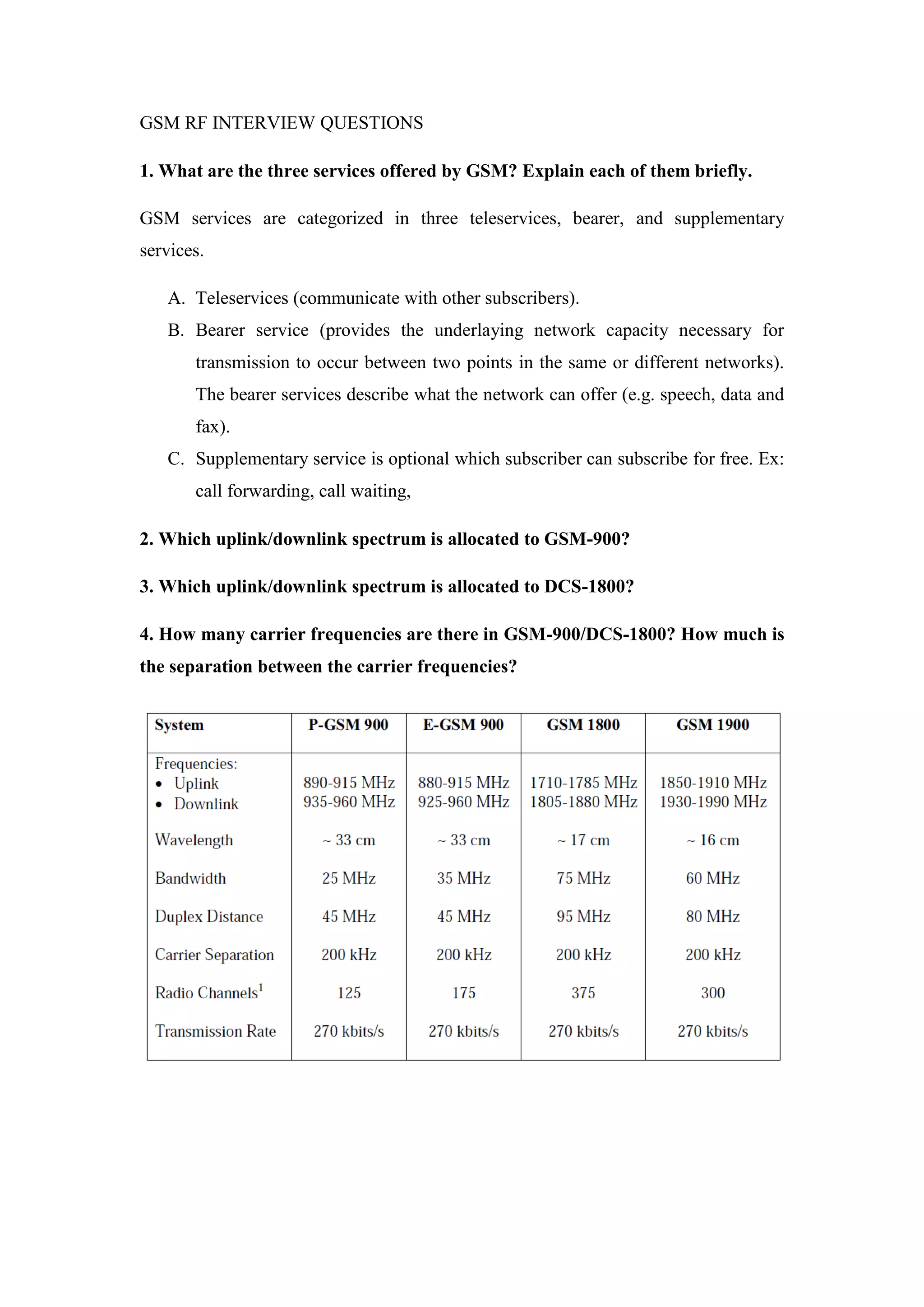
2. Spectrum allocation for GSM-900 and DCS-1800 networks.
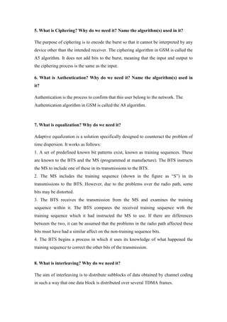
3. Concepts like ciphering, authentication, equalization, and interleaving which are used to secure communications and address issues like signal distortion over the air interface.
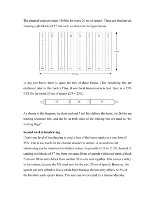
4. Channel coding and speech coding techniques used to compress voice data and add error correction for transmission.