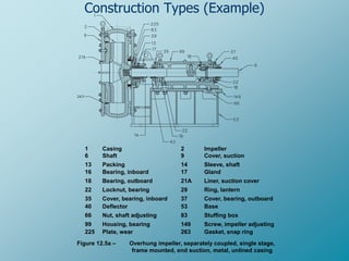
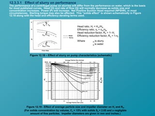
American National Standard for
Centrifugal Slurry Pumps
For Nomenclature Definitions,
Applications and Operation
Prepared By
Md Aminul Islam
Reliability Engineer
SADAF-SABIC,KSA
“WORKING DOCUMENT FOR HI COMMITTEE USE ONLY”
NOT FOR PUBLICATION
ANSI/HI 12.1-12.7 2001
12.0 Scope
This Standard is for centrifugal, single stage,
overhung slurry pumps horizontal and vertical
of industrial types. It includes types and
nomenclature; definitions; design and
application; and installation, operation and
maintenance.
12.1 Objective
To clearly outline information necessary to
define, select, apply, operate and maintain
centrifugal slurry pumps.
Figure 12.1 – Centrifugal slurry pump types
Centrifugal
Overhung Impeller
Single Stage
Frame
Mounted
Separately
Coupled
Wet Pit
Cantilever
Lined
Unlined
Lined
Unlined
Close
Coupled
Lined
Unlined
Metal Lined Fig. 12.3
Fig. 12.4a
Elastomer Lined
Metal
B73.1(note 1)
Fig. 12.5a
Fig. 12.5b
Fig. 12.5c
Fig. 12.6
Fig. 12.8
Elastomer Lined
Fig. 12.7a
Elastomer Lined
Metal
Metal
Note 1: B73.1 pumps used in slurry services normally require greater than normal thicknesses on parts exposed to slurry
Fig. 12.10b
Fig. 12.4b
Fig. 12.4c
Fig. 12.10a
Fig. 12.7b
Fig. 12.9a
Fig. 12.9b
Submersible
12.1.4 Definition (and application) of slurry pumps
A slurry pump is defined as a pump suitable for pumping the slurry in the
particular application. Slurry pumps vary in construction as much as the
properties of slurry, they are generally more robust than the pumps used in clean
liquid services, and they often have replaceable wear parts. Figure 12.2 shows
how various designs of slurry pumps are generally used.
Zone1. Rubber or Metal Centrifugal – Note: Total head
generation with rubber impellers is generally limited
to 40m/stage
Zone 2. Metal Centrifugal
Figure 12.2
Construction Types (Example)
1 Casing 2 Impeller
6 Shaft 9 Cover, suction
13 Packing 14 Sleeve, shaft
16 Bearing, inboard 17 Gland
18 Bearing, outboard 21A Liner, suction cover
22 Locknut, bearing 29 Ring, lantern
35 Cover, bearing, inboard 37 Cover, bearing, outboard
40 Deflector 53 Base
66 Nut, shaft adjusting 83 Stuffing box
99 Housing, bearing 149 Screw, impeller adjusting
225 Plate, wear 263 Gasket, snap ring
Figure 12.5a – Overhung impeller, separately coupled, single stage,
frame mounted, end suction, metal, unlined casing
12.2.9 Slurry Terminology (Sample)
12.2.9.1 Slurry
A mixture consisting of solid particles (specific gravity greater than 1) dispersed in a liquid.
12.2.9.2 Apparent viscosity
The viscosity of a non-Newtonian slurry at a particular rate of shear, expressed in terms applicable to Newtonian fluids.
12.2.9.3 Minimum carrying velocity
The velocity of the specific slurry in a particular conduit, above which the solids remain in suspension and below which
solid-liquid separation occurs.
12.2.9.4 Mean effective particle diameter, or average particle size
The single particle size used to represent the behavior of a mixture of various sizes of particles in slurry. This particle size is
where 50% by weight passes through a designated size screen. The d50 size is normally specified in microns but may also
be in other units, such as the as the Tyler Mesh, as shown in Figure 12.16. This d50 designation is used by some engineers
to calculate system requirements and pump performance. Figure 12.16 shows how it may be used to classify slurries and
provides different d50 size equivalents.
12.2.9.5 Solids mixture d85 size
The particle size, where 85% by weight passes through a designated size screen. The d85 size is normally expressed in
microns, but may also be in other units, such as the as the Tyler Mesh, as shown in Figure 12.16.
12.2.9.6 Maximum particle size
The maximum particle size expected in the slurry, under normal conditions, that has to pass though the pump.
12.2.9.7 Friction characteristic
A term used to describe the resistance to flow, which is exhibited by solid-liquid mixtures at various rates of flow.
12.2.9.8 Heterogeneous mixture
A mixture of solids and a liquid in which the solids are not uniformly distributed and tend to be more concentrated in the
bottom of the pipe.
12.2.9.9 Homogeneous mixture
A mixture of solids and a liquid in which the solids are uniformly distributed.
Figure 12.14 – Solids Transport Rate
Figure 12.17 – Nomograph for
maximum velocity
of stationary deposition.
12.3.3.1 Effect of slurry on performance
Head ratio, Hr = Hm/Hw
Efficiency ratio, ηr = ηm/ηw
Head reduction factor, Rh = 1- Hr
Efficiency reduction factor, Rη = 1-ηr
Where m is slurry
w is water
The performance of a centrifugal pump on slurries will differ from the performance on water, which is the basis
for most published curves. Head (H) and rate of flow (Q) will normally decrease as solids size and
concentration increases. Power (P) will increase. Net Positive Suction Head required (NPSHR), in most
circumstances. Starting torque may also be affected. This “solids effect” is shown schematically in Figure
12.18 along with the head and efficiency derating terms used.
Figure 12.18 – Effect of slurry on pump characteristics (schematic)
(For solids concentration by volume, Cv = 15% with solids Ss = 2.65 and a negligible
amount of fine particles. Impeller diameters are given in mm and inches.)
Figure 12.19 - Effect of average particle size and impeller diameter on Hr and Rh.
12.3.4 Froth Pumping
Froth is an aerated liquid medium (slurry) that occurs naturally or on purpose. Natural occurrence may be
due to the nature of the ore processed in the mineral industries creating a general nuisance in many cases.
Froth is created for the purpose of separating minerals floating the product from the waste or visa versa.
Froth is created by the aeration of the slurry through air injection during agitation with the addition of
polymers to increase the surface tension creating bubbles to which the product or waste adheres. This
allows for the separation and collection of the sought after mineral for further refining.
The transfer of froths with centrifugal slurry pumps is a special purpose application commonly encountered
in the launders of flotation circuits. The very large proportion of air in the froth being handled upsets the
normal relationships that are used to predict pumping performance and requires a unique approach in
selecting and applying pumps for this service.
It is well known that the presence of air at the suction inlet will decrease the head, flow and efficiency of a
pump and, with increasing amounts of air, the losses will also increase. The NPSH required increases with
increasing air content and at a certain critical level the pump loses prime and stops pumping. Studies done
with air injected into the suction of the pump have confirmed this but the data cannot be applied directly to
froth pumping.
Application Pump Froth Factor
Copper rougher concentrates 1.5
Copper cleaner concentrates 3.0
Molybdenum rougher concentrates 2.0
Molybdenum concentrates 3.0
Potash 2.0
Iron concentrates 4.0 to 6.0
Coal 6.0
Figure 12.20 shows how a froth factor is used to increase the process design capacity and select a pump for
the service. Example, for molybdenum, rougher concentrates with a design capacity of 225 cubic meters per
hour (990 us gpm) and the required head is 10 meters (33 feet). A 150mm (6”) discharge size pump would
normally be selected for this flow, but this example has a froth factor of 2.0. The factored capacity will be 450
cubic meters per hour (1981 us gpm). This flow rate is better suited to a 200mm (8”) pump. The original
condition point has been plotted on the curve along with the factored condition point. The required head
does not change and is simply transferred to the new flow rate. The pump speed will increase from 505 rpm
to 550 rpm as shown in the figure.
Table 12.5 - Approximate Froth Factors
12.3.5.2 Pump Wear
Pump wear depends on the pump design, the abrasivity of the slurry, the specifics of the
application or duty conditions, the way in which the pump is applied or selected for the duty
and the actual conditions of service.
Figure 12.23 - Erosive Wear Service Class
chart for slurry pumps
Service class
1 2 3 4
Max. head per stage:
meter
feet
123
400
66
225
52
168
40
130
Max. impeller peripheral speed:
All-metal pump
(m/s)
(ft/min)
43
8500
38
7500
33
6500
28
5500
Rubber-lined pump
(m/s)
(ft/min)
31
6000
28
5500
26
5000
23
4500
Table 12.6 - Suggested Maximum Value
for Acceptable Wear
Shaft Seals
The “weep type” arrangement, Figure 12.29, restricts flow into the pump by positioning the lantern ring between
the packing rings with a clean liquid injection at a higher pressure than pump discharge. Product dilution is
greatly reduced with this arrangement, but the slurry can penetrate the packing and wear the packing sleeve or
shaft, if the packing has not been carefully adjusted. This type of arrangement is recommended for Wear Service
Classes 2 and 3.
Figure 12.29 – “Weep type” stuffing box with lantern ring in extended position
Figure 12.30 – “Dry type” packing with Dynamic Seal
Mechanical Seals
Single spring elastomeric bellows seal (Figure 12.33 and Figure 12.34) - The non-pusher type elastomer bellows
seal has the advantage of free movement of the front section of the bellows and utilizes a non-clogging single
spring design. Non-pusher refers to the movement of the secondary seal along the shaft or sleeve. When
mounted as a stationary seal as shown in Figure 12.34 the probability of seal hang-up from leakage is decreased.
Figure 12.34 – Stationary elastomeric bellows seal
Figure 12.35 – Heavy duty slurry seal with quench device
Testing of nozzle loads on the above-described pumps has shown that mis-alignment between
the pump and motor shaft occurs from movement of the casing relative to the base plate. The
loading required for the movement is less than that which would produce excessive stresses in
the nozzles or internal distortion of parts. The amount of loading that result in movement
depends on the sizes of hold-down bolts, the amount of torque applied to the bolts and the
grade of bolts.
12.4.2 Nozzle Loads
Figure 12.40
The nozzle loads shown in Figure 12.40 are for those applied to cast-iron casings mounted on
machined mounting surface(s) of carbon steel base-plate. The loads are for Grade A ASTM
A307 bolts with no lubrication to the bolt threads.
This Slurry Pump Standard is
through the Slurry Standard
Committee Ballot and is now up
for consideration by the
Hydraulic Institute’s Standard
Voting Representative Ballot.

ANSI pump standard

  • 1.
    American National Standardfor Centrifugal Slurry Pumps For Nomenclature Definitions, Applications and Operation Prepared By Md Aminul Islam Reliability Engineer SADAF-SABIC,KSA “WORKING DOCUMENT FOR HI COMMITTEE USE ONLY” NOT FOR PUBLICATION ANSI/HI 12.1-12.7 2001
  • 2.
    12.0 Scope This Standardis for centrifugal, single stage, overhung slurry pumps horizontal and vertical of industrial types. It includes types and nomenclature; definitions; design and application; and installation, operation and maintenance. 12.1 Objective To clearly outline information necessary to define, select, apply, operate and maintain centrifugal slurry pumps.
  • 3.
    Figure 12.1 –Centrifugal slurry pump types Centrifugal Overhung Impeller Single Stage Frame Mounted Separately Coupled Wet Pit Cantilever Lined Unlined Lined Unlined Close Coupled Lined Unlined Metal Lined Fig. 12.3 Fig. 12.4a Elastomer Lined Metal B73.1(note 1) Fig. 12.5a Fig. 12.5b Fig. 12.5c Fig. 12.6 Fig. 12.8 Elastomer Lined Fig. 12.7a Elastomer Lined Metal Metal Note 1: B73.1 pumps used in slurry services normally require greater than normal thicknesses on parts exposed to slurry Fig. 12.10b Fig. 12.4b Fig. 12.4c Fig. 12.10a Fig. 12.7b Fig. 12.9a Fig. 12.9b Submersible
  • 4.
    12.1.4 Definition (andapplication) of slurry pumps A slurry pump is defined as a pump suitable for pumping the slurry in the particular application. Slurry pumps vary in construction as much as the properties of slurry, they are generally more robust than the pumps used in clean liquid services, and they often have replaceable wear parts. Figure 12.2 shows how various designs of slurry pumps are generally used. Zone1. Rubber or Metal Centrifugal – Note: Total head generation with rubber impellers is generally limited to 40m/stage Zone 2. Metal Centrifugal Figure 12.2
  • 5.
    Construction Types (Example) 1Casing 2 Impeller 6 Shaft 9 Cover, suction 13 Packing 14 Sleeve, shaft 16 Bearing, inboard 17 Gland 18 Bearing, outboard 21A Liner, suction cover 22 Locknut, bearing 29 Ring, lantern 35 Cover, bearing, inboard 37 Cover, bearing, outboard 40 Deflector 53 Base 66 Nut, shaft adjusting 83 Stuffing box 99 Housing, bearing 149 Screw, impeller adjusting 225 Plate, wear 263 Gasket, snap ring Figure 12.5a – Overhung impeller, separately coupled, single stage, frame mounted, end suction, metal, unlined casing
  • 6.
    12.2.9 Slurry Terminology(Sample) 12.2.9.1 Slurry A mixture consisting of solid particles (specific gravity greater than 1) dispersed in a liquid. 12.2.9.2 Apparent viscosity The viscosity of a non-Newtonian slurry at a particular rate of shear, expressed in terms applicable to Newtonian fluids. 12.2.9.3 Minimum carrying velocity The velocity of the specific slurry in a particular conduit, above which the solids remain in suspension and below which solid-liquid separation occurs. 12.2.9.4 Mean effective particle diameter, or average particle size The single particle size used to represent the behavior of a mixture of various sizes of particles in slurry. This particle size is where 50% by weight passes through a designated size screen. The d50 size is normally specified in microns but may also be in other units, such as the as the Tyler Mesh, as shown in Figure 12.16. This d50 designation is used by some engineers to calculate system requirements and pump performance. Figure 12.16 shows how it may be used to classify slurries and provides different d50 size equivalents. 12.2.9.5 Solids mixture d85 size The particle size, where 85% by weight passes through a designated size screen. The d85 size is normally expressed in microns, but may also be in other units, such as the as the Tyler Mesh, as shown in Figure 12.16. 12.2.9.6 Maximum particle size The maximum particle size expected in the slurry, under normal conditions, that has to pass though the pump. 12.2.9.7 Friction characteristic A term used to describe the resistance to flow, which is exhibited by solid-liquid mixtures at various rates of flow. 12.2.9.8 Heterogeneous mixture A mixture of solids and a liquid in which the solids are not uniformly distributed and tend to be more concentrated in the bottom of the pipe. 12.2.9.9 Homogeneous mixture A mixture of solids and a liquid in which the solids are uniformly distributed.
  • 7.
    Figure 12.14 –Solids Transport Rate
  • 8.
    Figure 12.17 –Nomograph for maximum velocity of stationary deposition.
  • 9.
    12.3.3.1 Effect ofslurry on performance Head ratio, Hr = Hm/Hw Efficiency ratio, ηr = ηm/ηw Head reduction factor, Rh = 1- Hr Efficiency reduction factor, Rη = 1-ηr Where m is slurry w is water The performance of a centrifugal pump on slurries will differ from the performance on water, which is the basis for most published curves. Head (H) and rate of flow (Q) will normally decrease as solids size and concentration increases. Power (P) will increase. Net Positive Suction Head required (NPSHR), in most circumstances. Starting torque may also be affected. This “solids effect” is shown schematically in Figure 12.18 along with the head and efficiency derating terms used. Figure 12.18 – Effect of slurry on pump characteristics (schematic) (For solids concentration by volume, Cv = 15% with solids Ss = 2.65 and a negligible amount of fine particles. Impeller diameters are given in mm and inches.) Figure 12.19 - Effect of average particle size and impeller diameter on Hr and Rh.
  • 10.
    12.3.4 Froth Pumping Frothis an aerated liquid medium (slurry) that occurs naturally or on purpose. Natural occurrence may be due to the nature of the ore processed in the mineral industries creating a general nuisance in many cases. Froth is created for the purpose of separating minerals floating the product from the waste or visa versa. Froth is created by the aeration of the slurry through air injection during agitation with the addition of polymers to increase the surface tension creating bubbles to which the product or waste adheres. This allows for the separation and collection of the sought after mineral for further refining. The transfer of froths with centrifugal slurry pumps is a special purpose application commonly encountered in the launders of flotation circuits. The very large proportion of air in the froth being handled upsets the normal relationships that are used to predict pumping performance and requires a unique approach in selecting and applying pumps for this service. It is well known that the presence of air at the suction inlet will decrease the head, flow and efficiency of a pump and, with increasing amounts of air, the losses will also increase. The NPSH required increases with increasing air content and at a certain critical level the pump loses prime and stops pumping. Studies done with air injected into the suction of the pump have confirmed this but the data cannot be applied directly to froth pumping. Application Pump Froth Factor Copper rougher concentrates 1.5 Copper cleaner concentrates 3.0 Molybdenum rougher concentrates 2.0 Molybdenum concentrates 3.0 Potash 2.0 Iron concentrates 4.0 to 6.0 Coal 6.0 Figure 12.20 shows how a froth factor is used to increase the process design capacity and select a pump for the service. Example, for molybdenum, rougher concentrates with a design capacity of 225 cubic meters per hour (990 us gpm) and the required head is 10 meters (33 feet). A 150mm (6”) discharge size pump would normally be selected for this flow, but this example has a froth factor of 2.0. The factored capacity will be 450 cubic meters per hour (1981 us gpm). This flow rate is better suited to a 200mm (8”) pump. The original condition point has been plotted on the curve along with the factored condition point. The required head does not change and is simply transferred to the new flow rate. The pump speed will increase from 505 rpm to 550 rpm as shown in the figure. Table 12.5 - Approximate Froth Factors
  • 11.
    12.3.5.2 Pump Wear Pumpwear depends on the pump design, the abrasivity of the slurry, the specifics of the application or duty conditions, the way in which the pump is applied or selected for the duty and the actual conditions of service. Figure 12.23 - Erosive Wear Service Class chart for slurry pumps Service class 1 2 3 4 Max. head per stage: meter feet 123 400 66 225 52 168 40 130 Max. impeller peripheral speed: All-metal pump (m/s) (ft/min) 43 8500 38 7500 33 6500 28 5500 Rubber-lined pump (m/s) (ft/min) 31 6000 28 5500 26 5000 23 4500 Table 12.6 - Suggested Maximum Value for Acceptable Wear
  • 12.
    Shaft Seals The “weeptype” arrangement, Figure 12.29, restricts flow into the pump by positioning the lantern ring between the packing rings with a clean liquid injection at a higher pressure than pump discharge. Product dilution is greatly reduced with this arrangement, but the slurry can penetrate the packing and wear the packing sleeve or shaft, if the packing has not been carefully adjusted. This type of arrangement is recommended for Wear Service Classes 2 and 3. Figure 12.29 – “Weep type” stuffing box with lantern ring in extended position Figure 12.30 – “Dry type” packing with Dynamic Seal
  • 13.
    Mechanical Seals Single springelastomeric bellows seal (Figure 12.33 and Figure 12.34) - The non-pusher type elastomer bellows seal has the advantage of free movement of the front section of the bellows and utilizes a non-clogging single spring design. Non-pusher refers to the movement of the secondary seal along the shaft or sleeve. When mounted as a stationary seal as shown in Figure 12.34 the probability of seal hang-up from leakage is decreased. Figure 12.34 – Stationary elastomeric bellows seal Figure 12.35 – Heavy duty slurry seal with quench device
  • 14.
    Testing of nozzleloads on the above-described pumps has shown that mis-alignment between the pump and motor shaft occurs from movement of the casing relative to the base plate. The loading required for the movement is less than that which would produce excessive stresses in the nozzles or internal distortion of parts. The amount of loading that result in movement depends on the sizes of hold-down bolts, the amount of torque applied to the bolts and the grade of bolts. 12.4.2 Nozzle Loads Figure 12.40 The nozzle loads shown in Figure 12.40 are for those applied to cast-iron casings mounted on machined mounting surface(s) of carbon steel base-plate. The loads are for Grade A ASTM A307 bolts with no lubrication to the bolt threads.
  • 15.
    This Slurry PumpStandard is through the Slurry Standard Committee Ballot and is now up for consideration by the Hydraulic Institute’s Standard Voting Representative Ballot.