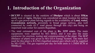
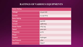
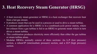
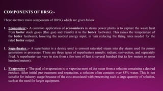
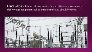
A
Training Seminar
On Summer Internship at
DHOLPUR COMBINED CYCLE POWER PLANT
Submitted to: Submitted by:
Dr. PRAVEEN KUMAR AGARWAL DURG SINGH
MNIT JAIPUR 2016UEE1142
CONTENTS
1. Introduction of the Organization
2. Gas Turbine (GT)
3. Heat Recovery Steam Generator (HRSG)
4. Steam Turbine (ST) & Condenser
5. Turbo Generator and Excitation System
6. 220KV Switchyard & Transformer and Maintenance Work
POWER PLANT
SELECTION OF SITES FOR THE GAS POWER PLANT
1.Supply of Water
2.Requirement of Land
3.Transportation Facility
4.Labor Supplies
5.Ash Disposal
6.Distance from The Populated Area
1. Cost of Plant Rs. 1155.15 Crore
2. Date of Synchronization UNIT I- 1 Sep 2007,
UNIT II- 1 Sep 2007,
UNIT III- 1 Jan 2008
3. Chimney Height 220m
4. Water Requirement 400m3/h
TECHNICAL DATA
GENERAL DATA:-
RATINGS OF VARIOUS EQUIPMENTS
Boiler Rating
Type High pressure boiler drum
Capacity 780 tons/hr.
Make BHEL
Steam Temperature 550 c
Steam Pressure 150 kg/cm2
Generator Rating
Make BHEL
Type Tg-Hh-0250-2
Capacity 250 MW
KVA 294100 KVA
RATINGS OF VARIOUS EQUIPMENTS
Stator Rating
Voltage 16,500Volt
Current 10,290 Amp
Rotor Rating
Voltage 319Volt
Current 2386 Amp
Power Factor 0.85 Lag
Speed 3000 rpm
Frequency 50 Hz
Phase 3
Coolant Hydrogen
Gas Pressure 3 Bar
Insulation Class F
2. GAS TURBINE (GT)
A. Working of Gas Turbine: -
• A gas turbine, also called a combustion turbine, is a rotary engine that extracts energy
from a flow of hot gas produced by combustion of gas in a stream of compressed air.
• It has an upstream air compressor radial or axial flow mechanically coupled to a
downstream turbine and a combustion chamber in between.
• Energy is relaxed when compressed air is mixed with fuel and ignited in the combustor.
• The resulting gases are directed over the turbine’s blades, spinning the turbine, and,
mechanically powering the compressor.
• Energy is extracted in the form of shaft power, compressed air and thrust, in any
combustion, and used to power electrical generators.
GAS TURBINE
B. Theory of Operation: -
DCCPP works on the principle of Brayton Cycle.
BRAYTON CYCLE:-
• The Brayton cycle named after the American Engineer George Brayton is a good model for the
operation of a gas turbines engine.
• Most turbines also try to recover exhaust heat, which otherwise is wasted energy, the heat released
from the exhaust gas has been absorbed by many kms of tubing which go to the boiler.
• Water is inside these tubes, , which takes the heat and is converted into steam at high temperature
and pressure.
• This type of boiler is called heat recovery steam generation (HRSG). This steam at high
temperature and pressure is sent to the turbine where it is discharged through the nozzles on to the
turbine blades.
• The energy of the steam striking on the blades makes the turbine to rotate.
3. Heat Recovery Steam Generator (HRSG)
• A heat recovery steam generator or HRSG is a heat exchanger that recovers heat
from a hot gas stream.
• It produces steam that can be used in a process or used to drive a steam turbine.
• A common application for a HRSG is in a combined-cycle power station, where
hot exhaust from a gas turbine is fed to an HRSG to generate steam which in turn
drives a steam turbine.
• This combination produces electricity more efficiently than either the gas turbine
or steam turbine alone.
• Modular HRSGs normally consist of three sections: An L.P (low pressure)
section, a reheat/IP (intermediate pressure) section, and a H.P (high pressure)
section.
COMPONENTS OF HRSG:-
There are three main components of HRSG which are given below
1. Economizer:- A common application of economizers in steam power plants is to capture the waste heat
from boiler stack gases (flue gas) and transfer it to the boiler feedwater. This raises the temperature of
the boiler feedwater, lowering the needed energy input, in turn reducing the firing rates needed for the
rated boiler output.
1. Superheater :- A superheater is a device used to convert saturated steam into dry steam used for power
generation or processes. There are three types of superheaters namely: radiant, convection, and separately
fired. A superheater can vary in size from a few tens of feet to several hundred feet (a few meters or some
hundred meters).
1. Evaporator :- The goal of evaporation is to vaporize most of the water from a solution containing a desired
product. After initial pre-treatment and separation, a solution often contains over 85% water. This is not
suitable for industry usage because of the cost associated with processing such a large quantity of solution,
such as the need for larger equipment.
SPECIFICATION OF BOILER DRUMS
1. HP Drum:
Design pressure 105Kg/Cm2
Working pressure 78.2 Kg/Cm2
Hydraulic pressure 157.5 Kg/Cm2
Water temperature Ambient
Holding time 10 min
HP steam 79.8 Kg/Cm2
Steam temp. 490 Deg C
2. LP Drum:
Design pressure 12 Kg/Cm2
Working pressure 5.0 Kg/Cm2
Hydraulic pressure 18 Kg/Cm2
Water temp. Ambient
Holding time 10 min
Steam temp. 220 Deg C
3. Chimney Exhaust:
Maximum temperature 90 Deg C
Working temperature 65- 70 Deg C
4. Steam Turbine (ST) & Condenser
STEAM TURBINE:
In a steam turbine steam is passed through nozzles or fixed blades where the heat drops take place increasing
the velocity of steam. The high velocity steams impinge on the curved vanes which causes the direction of the
steam to be changed. Due to this change of momentum motive force is exerted on the moving blades and
power is obtained.
Working of Steam Turbine:
• The steam turbine is a Siemens Westinghouse KN Turbines Generator, capable of producing up to 240 MW.
It is located on top of the condenser, across from the cooling tower.
• Steam enters the turbine with temperatures as high as 1000 degrees Fahrenheit and pressure as strong as
2,200 pounds per square inch. The pressure of the steam is used to spin turbine blades that are attached to a
rotor and generator, producing additional electricity about 100 MW per HRSG unit.
• After the steam is spent in the turbine process, the residual steam leaves the turbine at low pressure and low
heat about 100 degrees. This exhaust steam passes into a condenser, to be turned back into water.
• By using this “combined-cycle” process, two gas turbines and one steam turbine, we can produce a total of
about 110 MW of electricity.
Losses in Steam Turbine:
There are some losses in steam turbine.
• Loss in the exit velocity of steam
• Loss due to friction and turbulence
• Loss due to leakage
• Losses due to mechanical friction to the bearing, etc. this loss is less than 1 % and it
decreases with the size of the plant.
• Governor losses
• Exhaust losses
CONDENSER:
• The purpose of the condenser is to turn low energy steam back into pure water for use in
the Heat Recovery System Generator.
• A condenser makes it possible to remove exhaust economically at a pressure less than
that of atmosphere, thus by use of a condenser in a team plant low exhaust pressure can
be used and large heat drop per kg of steam utilized increasing both the efficiency and
power output of the plant.
Elements of Condensing plant:
• The condenser where steam is condensed.
• The condensate pumps for extracting water for the condenser to the hot well.
• The hot well for collecting the condensate.
• The air ejector or dry air pump for removing the non-condensable gases from the
condenser.
• The circulating water pump for circulating the cooling water.
• The cooling tower if same circulating water is to be used again and again.
5.Turbo Generator and Excitation System
An turbo-generator is an electromechanical device that converts mechanical energy using a rotating magnetic
field.
Main Components of Generator:
• Stator – Stator Frame (Fabrication & Machining)
• Core Assembly – Stator Core, Core Suspension Arrangement
• End shield
• Stator Winding Assembly – Stator Winding, Winding Assembly, Connecting Bus Bar, Terminal Bushing
• Rotor – Rotor Shaft, Rotor Wedges, Rotor Coils, Wound Rotor, Rotor Assembly
• Completing Assembly – Bearing Assembly, Shaft Seal Assembly, Oil Catchers, Insert Cover etc.
• Exciter
• Auxiliary system
Functions of Excitation System:
• Generation of air gap flux to get electrical output.
• To generate synchronizing torque to keep the machine in synchronism.
• To generate reactive power (MVAR)
• Fast response to system disturbances.
• Capability to generate field forcing condition for prompt clearance of faults.
Brushless Excitation System:
• Contact less system
• Eliminates all problem related to transfer of power between stationary and rotating elements.
• Completely eliminates brush gear, slip rings, field breaker
• Eliminates the hazard of changing
• Brushes on load
• Brush losses are eliminated
• Reliability is better
• Ideally suited for large sets
EXCITATION SYSTEM
6. 220KV Switchyard & Transformer and
Maintenance Work
STRUCTURE OF SWITCHYARD:-
1.Earthing of substation
2.Earth mat or High Resistance Mat (stones)
3.Ground Clearance
1.Earthing of substation:- Earthing system is made of a mesh of buried
bare copper cable, with additional earth rods
2.HIGH RESISTANCE MAT:- Stone increase resistance of
soil, step potential, and the touch potential limit decrease.
TOUCH POTENTIAL:-
It is the voltage between energized
object and the feet of a person in
contact with the object.
STEP POTENTIAL:-
It is defined as the maximum
potential difference that exists
between the feet when a fault
current flows.
3.GROUND CLEARANCE:-
Ground clearance is the vertical clearance
between the live parts of the equipment and the
earth surface.
(1)General ground clearance
(2)Technical ground clearance
LIST OF SWITCHYARD EQUIPMENT
1. Lightening arrestor
2. Corona ring
3. Capacitor voltage transformer
4. Wave trap
5. Line reactor
6. Isolator
7. Current transformer
8. Circuit breaker
9. Bus bar
10. Transformers
11. Bus reactor
12. Insulator
1. Lightening arrestor:-
LAS are used to protect any part of power system and equipment against Lightning
Over voltages and Switching Surges .
Lightening arrester Surge counter
2.CORONA RING:-
Corona rings are used to prevent corona discharge that occurs in
high-voltage power lines. They are fixed at the end of bushings
and insulator strings.
Corona discharge Corona ring
3.Capacitor voltage transformer:- CVTs are used for metering and protection
purposes. They also serves the purpose of PLCC.
4.WAVE TRAP:-
It is parallel resonant circuit mounted inline on
HVAC transmission power lines to prevent the
trans-mission of high frequency carrier signal so
that it can be used in (PLCC).
WAVE TRAP
5.ISOLATOR:- It is an off load device. It is to efficiently isolate very
high voltage equipment such as transformers and circuit breakers.
6.SHUNT REACTOR:-Shunt reactors are used in power systems to
counteract the effect of the line capacitance thereby stabilizing the system
voltage within acceptable limits.
50 MVAR Shunt Reactor
7.CURRENT TRANSFORMER:-Current Transformers (CTs) are used to transform
high voltage line current to a low standard value. So that high current is easy to handle for
measuring and protective relays.
Construction wise type of CTs –
(1) Live tank CTs
(2) Dead tank CTs
Live Tank CTs
8.CIRCUIT BREAKER:-It is an automatically operated electrical on
load switch designed to protect an electrical circuit from damage
caused by overload or short circuit.
Types of CBs-
1. Oil circuit breakers (OCBs)
2. Vacuum circuit breaker (VCB)
3. SF6 Circuit Breakers
4. Air circuit breaker
SF6 CIRCUIT BREAKER:-
In this SF6 gas is used for arc quenching medium.
SF6 Circuit Breaker
9.BUS BAR:- It is defined as a conductor or a group of conductor used for
collecting electric power from the incoming feeders and distributes them to the
outgoing Feeders.
10.TRANSFORMER:- It is used in electric power transmission to step
down or step up the voltage.
Construction wise types –
(1) core type
(2) shell type
500 MVA ,400kV/220kV Autotransformer
(1)Steel Tank
(2)Core of transformer
(3)Windings
(4)Breather
(5)Thermometer
(6)Buchholz relay
(7)Bushing
(8)On load tap changer
(9)Radiator
(10) Oil pumps
(11)Conservator tank
(12)Pressure relief vent
(13)Tertiary Bushing
MAIN PARTS OF TRANSFROMER:-
Buchholz Relay
11.BUS REACTOR:- A bus reactor is a type of air core inductor connected
between two buses or two sections of the same bus in order to limit the
voltage transient on either bus.
12.INSULATOR:- Insulators are used in electrical equipment to
support and separate electrical conductors without allowing current
through themselves.
PIN TYPE STRAIN TYPE SUSPENSION TYPE
SUSPENSION TYPE
THANK YOU

Ppt of internship at dccpp

  • 1.
    A Training Seminar On SummerInternship at DHOLPUR COMBINED CYCLE POWER PLANT Submitted to: Submitted by: Dr. PRAVEEN KUMAR AGARWAL DURG SINGH MNIT JAIPUR 2016UEE1142
  • 2.
    CONTENTS 1. Introduction ofthe Organization 2. Gas Turbine (GT) 3. Heat Recovery Steam Generator (HRSG) 4. Steam Turbine (ST) & Condenser 5. Turbo Generator and Excitation System 6. 220KV Switchyard & Transformer and Maintenance Work
  • 4.
  • 5.
    SELECTION OF SITESFOR THE GAS POWER PLANT 1.Supply of Water 2.Requirement of Land 3.Transportation Facility 4.Labor Supplies 5.Ash Disposal 6.Distance from The Populated Area
  • 6.
    1. Cost ofPlant Rs. 1155.15 Crore 2. Date of Synchronization UNIT I- 1 Sep 2007, UNIT II- 1 Sep 2007, UNIT III- 1 Jan 2008 3. Chimney Height 220m 4. Water Requirement 400m3/h TECHNICAL DATA GENERAL DATA:-
  • 7.
    RATINGS OF VARIOUSEQUIPMENTS Boiler Rating Type High pressure boiler drum Capacity 780 tons/hr. Make BHEL Steam Temperature 550 c Steam Pressure 150 kg/cm2 Generator Rating Make BHEL Type Tg-Hh-0250-2 Capacity 250 MW KVA 294100 KVA
  • 8.
    RATINGS OF VARIOUSEQUIPMENTS Stator Rating Voltage 16,500Volt Current 10,290 Amp Rotor Rating Voltage 319Volt Current 2386 Amp Power Factor 0.85 Lag Speed 3000 rpm Frequency 50 Hz Phase 3 Coolant Hydrogen Gas Pressure 3 Bar Insulation Class F
  • 9.
    2. GAS TURBINE(GT) A. Working of Gas Turbine: - • A gas turbine, also called a combustion turbine, is a rotary engine that extracts energy from a flow of hot gas produced by combustion of gas in a stream of compressed air. • It has an upstream air compressor radial or axial flow mechanically coupled to a downstream turbine and a combustion chamber in between. • Energy is relaxed when compressed air is mixed with fuel and ignited in the combustor. • The resulting gases are directed over the turbine’s blades, spinning the turbine, and, mechanically powering the compressor. • Energy is extracted in the form of shaft power, compressed air and thrust, in any combustion, and used to power electrical generators.
  • 10.
  • 11.
    B. Theory ofOperation: - DCCPP works on the principle of Brayton Cycle. BRAYTON CYCLE:- • The Brayton cycle named after the American Engineer George Brayton is a good model for the operation of a gas turbines engine. • Most turbines also try to recover exhaust heat, which otherwise is wasted energy, the heat released from the exhaust gas has been absorbed by many kms of tubing which go to the boiler. • Water is inside these tubes, , which takes the heat and is converted into steam at high temperature and pressure. • This type of boiler is called heat recovery steam generation (HRSG). This steam at high temperature and pressure is sent to the turbine where it is discharged through the nozzles on to the turbine blades. • The energy of the steam striking on the blades makes the turbine to rotate.
  • 12.
    3. Heat RecoverySteam Generator (HRSG) • A heat recovery steam generator or HRSG is a heat exchanger that recovers heat from a hot gas stream. • It produces steam that can be used in a process or used to drive a steam turbine. • A common application for a HRSG is in a combined-cycle power station, where hot exhaust from a gas turbine is fed to an HRSG to generate steam which in turn drives a steam turbine. • This combination produces electricity more efficiently than either the gas turbine or steam turbine alone. • Modular HRSGs normally consist of three sections: An L.P (low pressure) section, a reheat/IP (intermediate pressure) section, and a H.P (high pressure) section.
  • 13.
    COMPONENTS OF HRSG:- Thereare three main components of HRSG which are given below 1. Economizer:- A common application of economizers in steam power plants is to capture the waste heat from boiler stack gases (flue gas) and transfer it to the boiler feedwater. This raises the temperature of the boiler feedwater, lowering the needed energy input, in turn reducing the firing rates needed for the rated boiler output. 1. Superheater :- A superheater is a device used to convert saturated steam into dry steam used for power generation or processes. There are three types of superheaters namely: radiant, convection, and separately fired. A superheater can vary in size from a few tens of feet to several hundred feet (a few meters or some hundred meters). 1. Evaporator :- The goal of evaporation is to vaporize most of the water from a solution containing a desired product. After initial pre-treatment and separation, a solution often contains over 85% water. This is not suitable for industry usage because of the cost associated with processing such a large quantity of solution, such as the need for larger equipment.
  • 14.
    SPECIFICATION OF BOILERDRUMS 1. HP Drum: Design pressure 105Kg/Cm2 Working pressure 78.2 Kg/Cm2 Hydraulic pressure 157.5 Kg/Cm2 Water temperature Ambient Holding time 10 min HP steam 79.8 Kg/Cm2 Steam temp. 490 Deg C
  • 15.
    2. LP Drum: Designpressure 12 Kg/Cm2 Working pressure 5.0 Kg/Cm2 Hydraulic pressure 18 Kg/Cm2 Water temp. Ambient Holding time 10 min Steam temp. 220 Deg C 3. Chimney Exhaust: Maximum temperature 90 Deg C Working temperature 65- 70 Deg C
  • 16.
    4. Steam Turbine(ST) & Condenser STEAM TURBINE: In a steam turbine steam is passed through nozzles or fixed blades where the heat drops take place increasing the velocity of steam. The high velocity steams impinge on the curved vanes which causes the direction of the steam to be changed. Due to this change of momentum motive force is exerted on the moving blades and power is obtained. Working of Steam Turbine: • The steam turbine is a Siemens Westinghouse KN Turbines Generator, capable of producing up to 240 MW. It is located on top of the condenser, across from the cooling tower. • Steam enters the turbine with temperatures as high as 1000 degrees Fahrenheit and pressure as strong as 2,200 pounds per square inch. The pressure of the steam is used to spin turbine blades that are attached to a rotor and generator, producing additional electricity about 100 MW per HRSG unit. • After the steam is spent in the turbine process, the residual steam leaves the turbine at low pressure and low heat about 100 degrees. This exhaust steam passes into a condenser, to be turned back into water. • By using this “combined-cycle” process, two gas turbines and one steam turbine, we can produce a total of about 110 MW of electricity.
  • 17.
    Losses in SteamTurbine: There are some losses in steam turbine. • Loss in the exit velocity of steam • Loss due to friction and turbulence • Loss due to leakage • Losses due to mechanical friction to the bearing, etc. this loss is less than 1 % and it decreases with the size of the plant. • Governor losses • Exhaust losses
  • 18.
    CONDENSER: • The purposeof the condenser is to turn low energy steam back into pure water for use in the Heat Recovery System Generator. • A condenser makes it possible to remove exhaust economically at a pressure less than that of atmosphere, thus by use of a condenser in a team plant low exhaust pressure can be used and large heat drop per kg of steam utilized increasing both the efficiency and power output of the plant. Elements of Condensing plant: • The condenser where steam is condensed. • The condensate pumps for extracting water for the condenser to the hot well. • The hot well for collecting the condensate. • The air ejector or dry air pump for removing the non-condensable gases from the condenser. • The circulating water pump for circulating the cooling water. • The cooling tower if same circulating water is to be used again and again.
  • 19.
    5.Turbo Generator andExcitation System An turbo-generator is an electromechanical device that converts mechanical energy using a rotating magnetic field. Main Components of Generator: • Stator – Stator Frame (Fabrication & Machining) • Core Assembly – Stator Core, Core Suspension Arrangement • End shield • Stator Winding Assembly – Stator Winding, Winding Assembly, Connecting Bus Bar, Terminal Bushing • Rotor – Rotor Shaft, Rotor Wedges, Rotor Coils, Wound Rotor, Rotor Assembly • Completing Assembly – Bearing Assembly, Shaft Seal Assembly, Oil Catchers, Insert Cover etc. • Exciter • Auxiliary system
  • 20.
    Functions of ExcitationSystem: • Generation of air gap flux to get electrical output. • To generate synchronizing torque to keep the machine in synchronism. • To generate reactive power (MVAR) • Fast response to system disturbances. • Capability to generate field forcing condition for prompt clearance of faults. Brushless Excitation System: • Contact less system • Eliminates all problem related to transfer of power between stationary and rotating elements. • Completely eliminates brush gear, slip rings, field breaker • Eliminates the hazard of changing • Brushes on load • Brush losses are eliminated • Reliability is better • Ideally suited for large sets
  • 21.
  • 22.
    6. 220KV Switchyard& Transformer and Maintenance Work STRUCTURE OF SWITCHYARD:- 1.Earthing of substation 2.Earth mat or High Resistance Mat (stones) 3.Ground Clearance
  • 23.
    1.Earthing of substation:-Earthing system is made of a mesh of buried bare copper cable, with additional earth rods
  • 24.
    2.HIGH RESISTANCE MAT:-Stone increase resistance of soil, step potential, and the touch potential limit decrease.
  • 25.
    TOUCH POTENTIAL:- It isthe voltage between energized object and the feet of a person in contact with the object. STEP POTENTIAL:- It is defined as the maximum potential difference that exists between the feet when a fault current flows.
  • 26.
    3.GROUND CLEARANCE:- Ground clearanceis the vertical clearance between the live parts of the equipment and the earth surface. (1)General ground clearance (2)Technical ground clearance
  • 27.
    LIST OF SWITCHYARDEQUIPMENT 1. Lightening arrestor 2. Corona ring 3. Capacitor voltage transformer 4. Wave trap 5. Line reactor 6. Isolator 7. Current transformer 8. Circuit breaker 9. Bus bar 10. Transformers 11. Bus reactor 12. Insulator
  • 28.
    1. Lightening arrestor:- LASare used to protect any part of power system and equipment against Lightning Over voltages and Switching Surges . Lightening arrester Surge counter
  • 29.
    2.CORONA RING:- Corona ringsare used to prevent corona discharge that occurs in high-voltage power lines. They are fixed at the end of bushings and insulator strings. Corona discharge Corona ring
  • 30.
    3.Capacitor voltage transformer:-CVTs are used for metering and protection purposes. They also serves the purpose of PLCC.
  • 31.
    4.WAVE TRAP:- It isparallel resonant circuit mounted inline on HVAC transmission power lines to prevent the trans-mission of high frequency carrier signal so that it can be used in (PLCC). WAVE TRAP
  • 32.
    5.ISOLATOR:- It isan off load device. It is to efficiently isolate very high voltage equipment such as transformers and circuit breakers.
  • 33.
    6.SHUNT REACTOR:-Shunt reactorsare used in power systems to counteract the effect of the line capacitance thereby stabilizing the system voltage within acceptable limits. 50 MVAR Shunt Reactor
  • 34.
    7.CURRENT TRANSFORMER:-Current Transformers(CTs) are used to transform high voltage line current to a low standard value. So that high current is easy to handle for measuring and protective relays. Construction wise type of CTs – (1) Live tank CTs (2) Dead tank CTs
  • 35.
  • 36.
    8.CIRCUIT BREAKER:-It isan automatically operated electrical on load switch designed to protect an electrical circuit from damage caused by overload or short circuit. Types of CBs- 1. Oil circuit breakers (OCBs) 2. Vacuum circuit breaker (VCB) 3. SF6 Circuit Breakers 4. Air circuit breaker
  • 37.
    SF6 CIRCUIT BREAKER:- Inthis SF6 gas is used for arc quenching medium.
  • 38.
  • 39.
    9.BUS BAR:- Itis defined as a conductor or a group of conductor used for collecting electric power from the incoming feeders and distributes them to the outgoing Feeders.
  • 40.
    10.TRANSFORMER:- It isused in electric power transmission to step down or step up the voltage. Construction wise types – (1) core type (2) shell type
  • 41.
    500 MVA ,400kV/220kVAutotransformer
  • 42.
    (1)Steel Tank (2)Core oftransformer (3)Windings (4)Breather (5)Thermometer (6)Buchholz relay (7)Bushing (8)On load tap changer (9)Radiator (10) Oil pumps (11)Conservator tank (12)Pressure relief vent (13)Tertiary Bushing MAIN PARTS OF TRANSFROMER:- Buchholz Relay
  • 43.
    11.BUS REACTOR:- Abus reactor is a type of air core inductor connected between two buses or two sections of the same bus in order to limit the voltage transient on either bus.
  • 44.
    12.INSULATOR:- Insulators areused in electrical equipment to support and separate electrical conductors without allowing current through themselves. PIN TYPE STRAIN TYPE SUSPENSION TYPE SUSPENSION TYPE
  • 45.