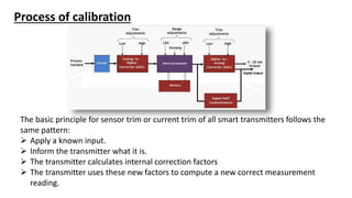
SMART TRANSMITTERS
Sensors & Transmitters ??
• Sensor senses the process variable like temperature, level, flow, pressure, pH,
conductivity etc to produces a corresponding electrical signal. This signal is
mostly in mV or low resistance range. This can not be used easily for any
meaningful measurement or control.
• A Transmitter in process control is a device that converts the signal produced by a
sensor into a standard instrumentation signal representing a process variable
being measured and controlled.
• Transmitters produce signal in more user friendly signal formats like 4-20 mA.
Conventional Transmitters
Only analog signal is available as output.
Physical zero or span buttons or pot available to calibrate.
Calibration possible by physical visit to the site.
Smart Transmitters
 SMART stands for Single Modular Auto-ranging Remote Transducer.
 SMART transmitters compared to analog transmitters have microprocessor
as their integral part , which helps for self diagnostic abilities , non-linear
compensations , re-ranging without performing calibrations ,and ability to
communicate digitally over the network.
1) Software : Configuration Options, User can select from various options on
Ranges, response, Display info, Outputs, etc
2) Sensor Characterization Data : Sensor data stored in the memory (EPROM).
Sensor behavior at various operating conditions is tested, and used for
compensation. It Drastically reduces drifts.
3 ) Store (and transmit when required) info such as :
tag - for identification of transmitter
date modified - date of last or next calibration or installation
message - name of person or some special precaution etc.
information on flange type, flange material O-ring, seal type, sensor range etc.
Functionality of Smart Transmitters
4) Processing signals: Enables Computations and Output Signal Options
linear : for pressure, differential pressure, level measurement. ..,
square root : for flow measurement with differential pressure meters,
square root of third and fifth powers : for flow measurement in open channels..
use values stored in table : to calculate the value of process variable
5) Re-ranging, Turn-down : Adjust or Change the zero / span
Send Command from Handheld/remote computer to the Process Transmitter
Re-ranging can be performed without applying reference (pressure /
temperature); It uses Characterization data.
6) Limits / Alarm values : High limit, low limit, high rate of change, low rate of
change can be set as alarm. Also failsafe values can be set.
7) Self-diagnostics : diagnostic to determine conditions of sensor, communication
line, power supply, configurations, etc. helps reduce trouble shooting efforts,
improves servicing.
8) Improved Safety : Re-ranging, calibration, etc., can be done remotely without going
to the actual transmitter site which may be in an hazardous or unsafe location.
9) High Accuracy : The process of analog-to-digital and digital-to-analog conversion of
the 4-20 signal are eliminated by the use of digital communication.
Functions like sensor output compensation for drifts due to changing operating
conditions, output linearization or other computations, etc. enable high accuracy of
transmitted data.
10) Reduced Inventory : Facility to re-range the transmitter without loss of accuracy,
facility to configure the transmitter when using a different process media,
computational abilities like square-root extraction, etc., implies that only one type of
smart transmitter need to be purchased or maintained as spare for a wide range.
Advantages of Smart Transmitters over conventional
transmitters
 perform calculations. (Output transfer function like linear, square root)
 produce troubleshooting diagnostics.
 Better accuracy and stability.
 Uses digital communication protocol.
 Can enable Password protection to ward off unauthorised use.
 Programmable failsafe level output for the control.
 Remote calibration.
Types of communication protocol
HART
Foundation Fieldbus
Wireless Hart
Profibus
RS 485
Bluetooth
Wifi
Etc…
HART enabled Smart Transmitters
 HART (Highway Addressable Remote Transmitter) is a communication protocol.
 A HART transmitter contains both a conventional analogue mA signal and a digital
signal superimposed on top of the analogue signal.
 Since it also has the analogue signal, it is compatible with conventional
installations.
 HART standard helps instruments to digitally communicate with one another over
the same two wires used to convey a 4-20 mA analog instrument signal.
Calibration of Smart Transmitter
Although a Smart Transmitter is advertised as being smart and extremely accurate,
there is still a need to calibrate the instruments.
Calibration must always be a priority due to the following reasons:
 Most smart transmitters are exposed to harsh conditions. Thus, these instruments
drift over the time.
 To fulfill regulatory requirements, such as safety, quality systems, environmental
systems and standards, etc.
 Accurate measurements always lead to appropriate decision making, which may
bring various economic benefits.
 Regular calibration helps process owners to ensure workplace and employee safety.
 Calibration helps achieve consistent product quality by optimizing processes.
Process of calibration
The smart transmitter calibration procedure is known as digital trimming. It
needs to be done using either a digital hand held communicator or
advanced calibrators.
Sensor trim is the correction of the digital reading from
the sensor after the A/D conversion.
Re-ranging is configuration of the lower and
upper range values corresponding to the
input values at which the transmitter output
shall be 4 mA and 20 mA respectively.
Current trim is the correction of the analog output from
the transmitter
Process of calibration
The basic principle for sensor trim or current trim of all smart transmitters follows the
same pattern:
 Apply a known input.
 Inform the transmitter what it is.
 The transmitter calculates internal correction factors
 The transmitter uses these new factors to compute a new correct measurement
reading.
Thanks

Smart transmitters.pptx

  • 1.
  • 2.
    Sensors & Transmitters?? • Sensor senses the process variable like temperature, level, flow, pressure, pH, conductivity etc to produces a corresponding electrical signal. This signal is mostly in mV or low resistance range. This can not be used easily for any meaningful measurement or control. • A Transmitter in process control is a device that converts the signal produced by a sensor into a standard instrumentation signal representing a process variable being measured and controlled. • Transmitters produce signal in more user friendly signal formats like 4-20 mA.
  • 3.
    Conventional Transmitters Only analogsignal is available as output. Physical zero or span buttons or pot available to calibrate. Calibration possible by physical visit to the site.
  • 4.
    Smart Transmitters  SMARTstands for Single Modular Auto-ranging Remote Transducer.  SMART transmitters compared to analog transmitters have microprocessor as their integral part , which helps for self diagnostic abilities , non-linear compensations , re-ranging without performing calibrations ,and ability to communicate digitally over the network.
  • 5.
    1) Software :Configuration Options, User can select from various options on Ranges, response, Display info, Outputs, etc 2) Sensor Characterization Data : Sensor data stored in the memory (EPROM). Sensor behavior at various operating conditions is tested, and used for compensation. It Drastically reduces drifts. 3 ) Store (and transmit when required) info such as : tag - for identification of transmitter date modified - date of last or next calibration or installation message - name of person or some special precaution etc. information on flange type, flange material O-ring, seal type, sensor range etc. Functionality of Smart Transmitters
  • 6.
    4) Processing signals:Enables Computations and Output Signal Options linear : for pressure, differential pressure, level measurement. .., square root : for flow measurement with differential pressure meters, square root of third and fifth powers : for flow measurement in open channels.. use values stored in table : to calculate the value of process variable 5) Re-ranging, Turn-down : Adjust or Change the zero / span Send Command from Handheld/remote computer to the Process Transmitter Re-ranging can be performed without applying reference (pressure / temperature); It uses Characterization data. 6) Limits / Alarm values : High limit, low limit, high rate of change, low rate of change can be set as alarm. Also failsafe values can be set. 7) Self-diagnostics : diagnostic to determine conditions of sensor, communication line, power supply, configurations, etc. helps reduce trouble shooting efforts, improves servicing.
  • 7.
    8) Improved Safety: Re-ranging, calibration, etc., can be done remotely without going to the actual transmitter site which may be in an hazardous or unsafe location. 9) High Accuracy : The process of analog-to-digital and digital-to-analog conversion of the 4-20 signal are eliminated by the use of digital communication. Functions like sensor output compensation for drifts due to changing operating conditions, output linearization or other computations, etc. enable high accuracy of transmitted data. 10) Reduced Inventory : Facility to re-range the transmitter without loss of accuracy, facility to configure the transmitter when using a different process media, computational abilities like square-root extraction, etc., implies that only one type of smart transmitter need to be purchased or maintained as spare for a wide range.
  • 8.
    Advantages of SmartTransmitters over conventional transmitters  perform calculations. (Output transfer function like linear, square root)  produce troubleshooting diagnostics.  Better accuracy and stability.  Uses digital communication protocol.  Can enable Password protection to ward off unauthorised use.  Programmable failsafe level output for the control.  Remote calibration.
  • 9.
    Types of communicationprotocol HART Foundation Fieldbus Wireless Hart Profibus RS 485 Bluetooth Wifi Etc…
  • 10.
    HART enabled SmartTransmitters  HART (Highway Addressable Remote Transmitter) is a communication protocol.  A HART transmitter contains both a conventional analogue mA signal and a digital signal superimposed on top of the analogue signal.  Since it also has the analogue signal, it is compatible with conventional installations.  HART standard helps instruments to digitally communicate with one another over the same two wires used to convey a 4-20 mA analog instrument signal.
  • 11.
    Calibration of SmartTransmitter Although a Smart Transmitter is advertised as being smart and extremely accurate, there is still a need to calibrate the instruments. Calibration must always be a priority due to the following reasons:  Most smart transmitters are exposed to harsh conditions. Thus, these instruments drift over the time.  To fulfill regulatory requirements, such as safety, quality systems, environmental systems and standards, etc.  Accurate measurements always lead to appropriate decision making, which may bring various economic benefits.  Regular calibration helps process owners to ensure workplace and employee safety.  Calibration helps achieve consistent product quality by optimizing processes.
  • 12.
    Process of calibration Thesmart transmitter calibration procedure is known as digital trimming. It needs to be done using either a digital hand held communicator or advanced calibrators.
  • 13.
    Sensor trim isthe correction of the digital reading from the sensor after the A/D conversion. Re-ranging is configuration of the lower and upper range values corresponding to the input values at which the transmitter output shall be 4 mA and 20 mA respectively. Current trim is the correction of the analog output from the transmitter Process of calibration
  • 14.
    Process of calibration Thebasic principle for sensor trim or current trim of all smart transmitters follows the same pattern:  Apply a known input.  Inform the transmitter what it is.  The transmitter calculates internal correction factors  The transmitter uses these new factors to compute a new correct measurement reading.
  • 15.