Download to read offline
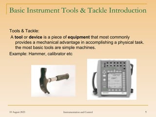

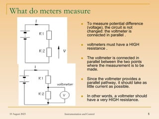
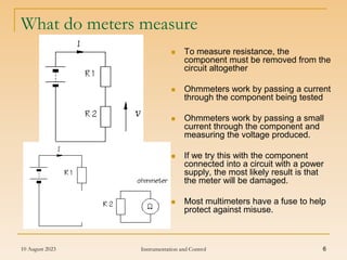
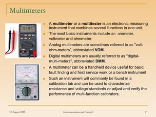
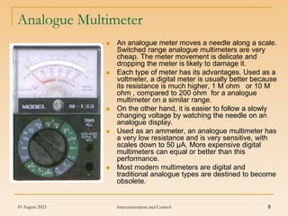
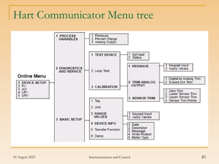
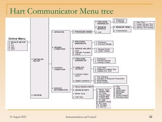
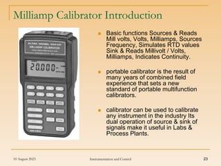
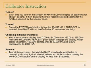


This document provides information about basic instrument tools and calibration tools. It discusses common tools used in instrumentation like multimeters, pressure calibrators and wrenches. It also describes how meters like ammeters, voltmeters and ohmmeters work and how they are connected in circuits. Finally, it discusses Hart communicators and milliamp calibrators, including their functions, menus and specifications.


