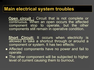
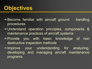
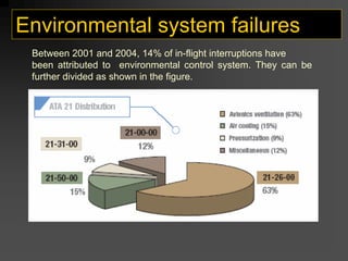
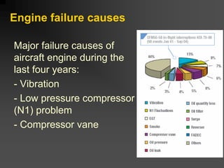
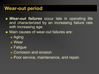
The document provides an overview of aircraft maintenance training. It covers topics like aircraft ground handling procedures, aircraft systems including hydraulic, pneumatic, flight control and landing gear systems, aircraft engines, and environmental control systems. The course outline includes sections on aircraft ground handling, aircraft systems, corrosion inspection methods, and aircraft maintenance planning. Key components and functions of different aircraft systems are described in further detail.

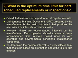
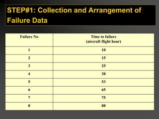
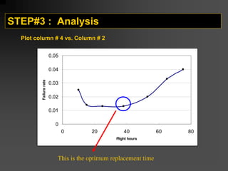
![STEP#2: Calculation of failure rate
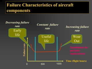
Failure rate
Time
between
failures
∆t
Time
to
failure
(flight hour)
Failure Number
( i )
1 / [(5)(8+1-1)]=0.025
10
1
0.014
15
2
0.013
13
25
3
0.013
15
38
4
0.020
12
53
5
0.033
10
65
6
0.040
13
75
7
-
-
88
8
)
i
1
n
)(
t
(
1
FR
−
+
Δ
=
n= 8 (total number of failures)
15-10=5
25-15=10
?](https://image.slidesharecdn.com/methodsofmaintenance-230926102851-687dc483/85/methods-of-maintenance-pdf-161-320.jpg)