![Amitabh Gairola [LION] amitaban1990@gmail.com, profile picture](https://cdn.slidesharecdn.com/profile-photo-AmitabhGairola1-48x48.jpg?cb=1527588730)
Downloaded 45 times


![19
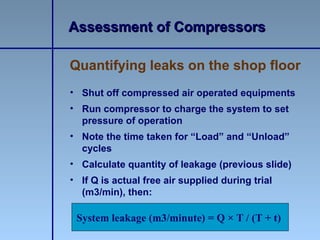
• Total leakage calculation:
T = on-load time (minutes)
t = off-load time (minutes)
• Well maintained system: less than 10%
leakages
Leak Quantification Method
Assessment of CompressorsAssessment of Compressors
Leakage (%) = [(T x 100) / (T + t)]](https://image.slidesharecdn.com/compressors-130530033006-phpapp01/85/Compressors-19-320.jpg)
![21
• Compressor capacity (m3/minute) = 35
• Cut in pressure, kg/cm2 = 6.8
• Cut out pressure, kg/cm2 = 7.5
• Load kW drawn = 188 kW
• Unload kW drawn = 54 kW
• Average ‘Load’ time =1.5 min
• Average ‘Unload’ time = 10.5 min
Example
Assessment of CompressorsAssessment of Compressors
Leakage = [(1.5)/(1.5+10.5)] x 35 = 4.375 m3/minute](https://image.slidesharecdn.com/compressors-130530033006-phpapp01/85/Compressors-21-320.jpg)


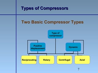
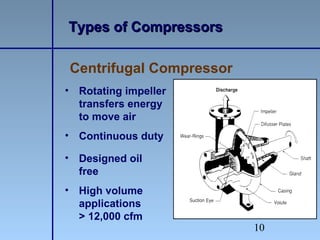
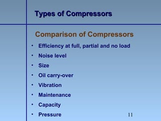
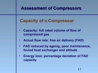
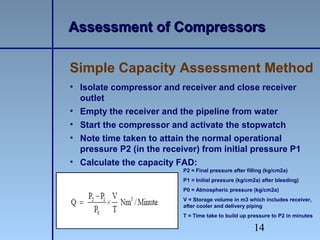
This document provides an overview of a training session on air compressors and compressed air systems. It discusses the different types of compressors including reciprocating, rotary, centrifugal and axial compressors. It also covers how to assess compressors and compressed air systems to determine capacity, efficiency and leaks. Finally, it outlines various energy efficiency opportunities such as optimizing pressure settings and intake air conditions, installing intercoolers and aftercoolers, minimizing leaks, and implementing proper maintenance practices.


