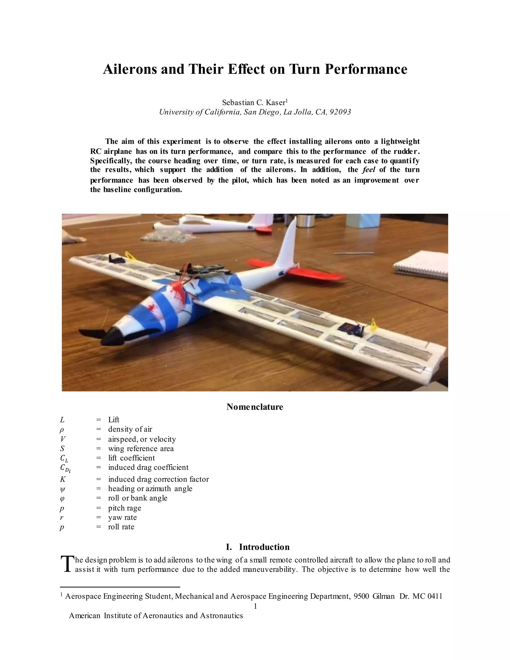
The document discusses an experiment to compare the turn performance of an RC airplane using ailerons versus using just the rudder. Flight tests were conducted to measure the turn rate for each case using a GPS data logger. Results showed the turn rate varied more when using ailerons but peak rates were mostly higher than when using just the rudder, indicating improved performance with the addition of ailerons. Some modifications were made to strengthen the wing and increase power to accommodate the added weight of the aileron control surfaces.
This document provides detailed instructions for a new technique called "Tru-Fit Fuselage Construction" developed by Robin Hunt and his son Robby Hunt. The technique allows for molded fuselage shells and a fuselage structure ("crutch") that are perfectly matched without gaps. The instructions explain how to make templates and mold bucks to produce top and bottom fuselage shells that will precisely fit the internal fuselage structure. Multiple templates, plates and mold bucks are cut from materials like balsa, plywood and foam to create molds that yield perfectly fitting shell components for complex fuselage shapes.
This document provides an overview of weight and balance concepts for aircraft. It defines key terms like empty weight, useful load, center of gravity, moment, and arm. It explains how weight and balance affects aircraft performance and safety. Maintaining the proper center of gravity is important for longitudinal stability and control. Being over or under weight limits can reduce performance and endurance or cause structural issues. The document also describes how to calculate weight and balance using information in the aircraft's Pilot Operating Handbook.
The document discusses inspections required on certificated aircraft according to FAR regulations. It covers the following key points:
- Owners are responsible for maintaining airworthiness and complying with inspections and airworthiness directives.
- Inspections required include annual inspections, 100-hour inspections, and inspections selected from FAA-approved programs depending on the aircraft type and operation.
- Additional inspections include altimeter and static system inspections every 24 months and transponder inspections every 24 months if the aircraft is equipped with a transponder.
1) An aircraft's static stability and center of gravity (CG) position depend on the CG being ahead of the aerodynamic center.
2) The CG position affects aircraft performance characteristics like stall speed, takeoff distance, and landing distance, as well as drag and fuel consumption.
3) The CG must remain within certified forward and aft limits that depend on the aircraft's weight and are expressed as a percentage of the mean aerodynamic chord.
This document discusses the structural design of aircraft. It begins by describing the basic components of an aircraft structure, including wings, fuselage, tail, and control surfaces. It then discusses the functions of different structural elements like skin, spars, ribs, stringers, and frames. It provides details on fuselage types, wing structure, empennage, landing gear, and materials used in aircraft construction. It concludes with an explanation of the V-n diagram used for structural design and load factors specified by airworthiness authorities.
The Chief Officer acts as the ship's Safety Officer and is responsible for ensuring proper maintenance of safety equipment and reporting of accidents. The Safety Officer ensures safety committee meetings are held regularly and minutes are submitted. It is the duty of the Safety Officer to maintain a safe working environment and comply with safety regulations. The Safety Officer is also responsible for maintaining the vessel's safety file which contains various safety records and documents. Regular safety meetings must be held to discuss safety issues and improvements.
The document describes the design and fabrication of a V-tail unmanned aerial vehicle (UAV). It aims to study the stability, design parameters, and operation of a V-tail configuration. The project involves designing all parts of the RC aircraft using CATIA software, performing calculations to determine dimensions, and assembling the final prototype. The design process considers various factors like material selection, component orientation, weight estimation, and control surface sizing. The report outlines the various stages of completing the project, from initial conceptualization to fabrication and testing of the final V-tail UAV model.
This document summarizes a seminar presentation on unmanned aerial vehicles (UAVs), also known as drones. It defines UAVs as aircraft without onboard pilots that are controlled remotely. The presentation covered types of UAVs, the necessity of UAVs in reducing risks to human life, methodology for UAV design including consideration of thrust, drag, lift and weight, applications such as surveillance and disaster relief, disadvantages including risks of hacking or losing control, and conclusions on the importance of UAVs and software used for design.
Under the guidance of Mr. Darshankumar Billur, the document discusses the history and classification of unmanned aerial vehicles (UAVs). It provides details on the different elements of UAV systems, including the airframe, propulsion, payload and ground control systems. A case study is presented on the Predator C Avenger UAV, covering its specifications and capabilities. Advantages of UAVs include reduced risks and longer flight times compared to manned aircraft, while disadvantages include higher costs and limited abilities. Applications discussed include remote sensing, surveillance, transport, search and rescue, and armed attacks.
The pressure distribution over an airfoil is represented by the pressure coefficient Cp, which is a nondimensional measurement of pressure. Cp is plotted against the chordwise location x/c to show that pressure decreases rapidly on the upper and lower surfaces near the leading edge before recovering further back. The lift generated by the airfoil is related to the difference in pressure between the upper and lower surfaces, as represented by the area between the Cp curves.
The document discusses weight and balance concepts for aircraft. It covers structural weight limitations, performance effects of being overweight, and the importance of center of gravity position for stability and controllability. Calculating an aircraft's center of gravity involves determining the basic empty weight, empty moment, and empty center of gravity, then accounting for changes in weight and moment from passengers, baggage, and fuel. The center of gravity position must remain within specified limits for safe flight.
This document analyzes the aerodynamic performance of three different wing configurations for unmanned air vehicles (UAVs) using computational fluid dynamics (CFD). The three wings analyzed are a hybrid wing, joined wing, and tailless wing. CFD simulations were run at varying Mach numbers and angles of attack. Results show the tailless wing generates the lowest vortices and has the highest lift-to-drag ratio and stall angle, indicating it provides the best aerodynamic performance of the three wings analyzed for UAV applications.
Abstract:
Landing gear is one of the critical subsystems of an aircraft. The need to design landing gear with minimum weight, minimum volume, high performance, improved life and reduced life cycle cost have posed many challenges to landing gear designers and practitioners. Further it is essential to reduce the landing gear design and development cycle time while meeting all the regulatory and safety requirements. Many technologies have been developed over the years to meet these challenges in design and development of landing gear. This paper presents a perspective on various stages of landing gear design and development, current technology landscape and how these technologies are helping us to meet the challenges involved in the development of landing gear and how they are going to evolve in future.
NAME : S. Srinivasa Phani Kumar
Branch : MECHANICAL
College : SWARNANDHRA COLLEGE OF ENGINEERING & TECHNOLOGY
This document provides information on several features of an ARPA radar system, including:
1. It describes how the Predicted Point of Collision (PPC) and Predicted Area of Danger (PAD) can be displayed to evaluate collision threats.
2. It explains that trial maneuvering simulations allow users to assess how targets will respond to potential course alterations before implementing them.
3. Past target positions can be shown to identify changes in course or speed over the last 8 minutes.
4. The results of trial maneuvers are approximations that depend on the system's own ship models and input course/speed alterations. Clear labeling distinguishes simulated from actual target data.
This document provides details of the third weight estimation for a small surveillance aircraft model. The total weight from the second estimation is 1045.3g. Design parameters like a NACA 2414 airfoil with 16cm chord, 1m wingspan, and 45.38N/m^2 wing loading are assumed. Balsa wood is selected as the construction material. Component weights like power plant (256g), payload (120g) are known. The third estimation will account for additional structural weights of the wings, fuselage, tail surfaces, and fittings to obtain the final total weight.
PRELIMINARY DESIGN APPROACH TO WING BOX LAYOUT AND STRUCTURAL CONFIGURATIONLahiru Dilshan
This is an assignment that was done to design the basic layout of the aircraft wing and structural configuration. Key aspects of the assignment are to design the structural layout, identify the basic component, identify the structural arrangement
Geoffrey Wardle has over 40 years of experience in air and space research and development. His career began in 1982 with designing coatings to protect rocket engine parts from corrosion for the LEROS liquid fuel rocket engine. In the 1980s and early 1990s, he conducted structural qualification testing for components of Eurofighter Typhoon and developed test methodologies at establishments including RAE Farnborough and BAe. Currently, he is researching advanced composite airframe technologies and supersonic bomber design using simulation tools from his graduate studies.
This technical paper presentation provides an overview of helicopter aerodynamics. Key topics covered include airfoils, rotary wing platforms, relative wind, angle of attack, total aerodynamic force, and factors that influence lift such as speed, area, angle of attack, and air density. The presentation defines important aerodynamic terms and illustrates concepts like induced flow and how it modifies the relative wind experienced by rotor blades in hover and forward flight.
SOLAS is the most important international treaty concerning maritime safety. It establishes minimum standards for the construction, equipment and operation of ships. SOLAS has undergone revisions and amendments over time to keep up with technological and operational advances. Key provisions address subdivision and stability, fire safety, life-saving appliances, safe navigation, dangerous cargo carriage, and ship security. SOLAS requires certifications and has different technical requirements depending on ship type and cargo. Its goal is to specify uniform safety standards to ensure ships remain safe and secure at sea.
This document is an introduction to an aviation law textbook. It provides definitions for key terms and abbreviations used in aviation law. The textbook is designed to cover the content of the JAA-FCL syllabus for the air law subject, including international agreements, rules of the air, flight crew licensing and more. It notes that while called "air law", the subject involves both legal and airmanship aspects. The introduction emphasizes that most of the content involves common sense topics familiar to pilots.
This document provides an overview of aircraft landing gear systems. It describes the main components, including the types of landing gear arrangements (tail wheel, tandem, tricycle), construction details, alignment and retraction mechanisms, nose wheel steering, braking systems, tires, and antiskid systems. The purpose of landing gear is to support the aircraft during landing and taxiing. Retractable gear stows in the fuselage or wings to reduce drag while flying. Nose wheel steering and braking systems provide directional control on the ground. Aircraft tires must withstand high loads and provide traction for takeoff and landing. Antiskid systems help maintain braking effectiveness.
The document discusses several types of aircraft navigation equipment, including VHF Omnidirectional Range (VOR) systems, Instrument Landing Systems (ILS), Distance Measuring Equipment (DME), Automatic Direction Finders (ADF), Doppler navigation systems, and Inertial Navigation Systems. It provides details on how each system works and the information it provides to pilots during flight.
The document discusses the International Maritime Organization (IMO), an agency of the United Nations that regulates international shipping. It outlines that the IMO was established in 1948 to improve vessel safety and prevent marine pollution. The IMO adopts international conventions covering issues like safety of life at sea, training of seafarers, and prevention of pollution from ships. Member states are required to adopt these conventions into their own laws. The document focuses on key IMO conventions regarding safety (SOLAS) and prevention of pollution (MARPOL).
RADAR is used for air traffic control and aircraft surveillance. It operates in the UHF and SHF bands using frequencies between 1-30 GHz. There are several types of RADAR used in aviation including en-route surveillance radar to track aircraft up to 300 NM, terminal approach radar for precision tracking near airports, and surface movement radar to monitor aircraft and vehicle movements on runways and taxiways. RADAR can use primary surveillance to detect aircraft via reflected pulses or secondary surveillance where aircraft transmit identification codes in response to interrogation signals.
The document discusses various technologies used in air traffic control and air navigation, including navigation aids like VOR, ILS, DME, RNAV, and satellite navigation. It also covers flight planning, airport charts, approach charts, and the role of the flight management system.
AIRCRAFT WEIGHT AND BALANCE BASIC FOR LOAD CONTROLjasmine jacob
The document discusses aircraft weight and balance requirements. It covers key topics such as:
1) Compliance with weight and balance limits is critical for flight safety, as exceeding maximum weight limits can compromise structural integrity and affect aircraft performance. Operating with the center of gravity outside approved limits can also cause control difficulties.
2) Proper load planning, distribution, and securing of cargo and baggage is required. Various aircraft compartments and structural loading limitations must be followed.
3) Dangerous goods and special items require special documentation and handling procedures. Records of weight and balance calculations must be retained for regulatory compliance.
Early pilots navigated visually by looking for landmarks but as flying occurred at night and in poor weather, new navigation technologies were developed. In the 1920s, navigation aids helped pilots determine attitude and position even when the ground was not visible. In 1929, Sperry introduced the artificial horizon and other mechanical aids emerged in the 1930s. Today, aircraft are tracked by radar but GPS now allows pilots to determine their precise position without assistance from air traffic control. This has led to debates around who should control navigation - pilots using GPS or air traffic controllers.
The document summarizes modeling a 2-input comparator circuit using PSpice. It includes the equivalent circuit diagram showing the two inputs (IN+ and IN-), output (OUT), and components including resistors R1-R3 and capacitor C1. The summary describes simulating the circuit by applying square wave input signals to test the output.
This document provides summaries of several wire artists:
- Sir Antony Gormley is a British sculptor best known for public works like the Angel of the North in England and Event Horizon installations in London, New York, and São Paulo.
- Gavin Worth was born in Zimbabwe and works as an actor, musician, and self-taught sculptor based in New Mexico.
- David Oliveira is a Portuguese sculptor who holds a degree from Lisbon University and creates wire sculptures that play with optical illusions and the appearance of sketches suspended in space.
- Diane Komater was inspired by stained glass windows as a child and now creates wire sculptures.
- Derek Kinzett is a British wire sculpt
PT. Jeklindo Consulting menawarkan berbagai jasa konsultasi perijinan usaha di Indonesia, termasuk penerbitan izin usaha, perijinan impor, dan dokumen lainnya. Perusahaan ini memiliki pengalaman dalam mengurus berbagai dokumen perijinan untuk perusahaan maupun individu.
El documento describe el uso del tiempo de una persona a lo largo de la semana. Se divide el tiempo en cuatro cuadrantes: cumplimiento de objetivos laborales, superación personal, tareas domésticas, y distracciones. El documento analiza cómo el uso del tiempo en cada cuadrante afecta los resultados como estrés, cansancio y cumplimiento de metas.
This was my final year project thesis, based on the results from NASA Langley Research Centre’s work on the PRANDTL-D project which was into minimizing the induced drag of a wing body along with elimination of adverse yaw.
IRJET-Subsonic Flow Study and Analysis on Rotating Cylinder AirfoilIRJET Journal
This document presents a study on modifying the lift characteristics of a conventional symmetrical airfoil (NACA 0012) by adding a rotating cylinder. A numerical analysis and computational fluid dynamics simulation were conducted. Two cases were considered: a cylinder with 13mm diameter located at the 0.125 chord point, and a 15mm cylinder at the 0.25 chord point. The presence of a rotating cylinder was found to significantly increase the airfoil's lift at zero angle of attack through momentum injection, by up to 100%. It also delayed stall characteristics. The document outlines the methodology, including the airfoil geometry, range of air velocities and cylinder rotation speeds studied, and equations used to model static and total pressure.
A Good Effect of Airfoil Design While Keeping Angle of Attack by 6 Degreepaperpublications3
Abstract: Airfoil is a shape of wing or blade of (a propeller, rotor or turbine) by which a fluid generates an aerodynamic force. The component of this force perpendicular to the direction of its speed is called lift force and the component parallel to its speed is called drag forces. Here we see that if we set the angle of attack by 6 degree in fluid NACA0012 we found the aerodynamic forces with suitable positive result our research is totally based on iterations method and based on the help of cfd software.
International Journal of Engineering Research and Applications (IJERA) is an open access online peer reviewed international journal that publishes research and review articles in the fields of Computer Science, Neural Networks, Electrical Engineering, Software Engineering, Information Technology, Mechanical Engineering, Chemical Engineering, Plastic Engineering, Food Technology, Textile Engineering, Nano Technology & science, Power Electronics, Electronics & Communication Engineering, Computational mathematics, Image processing, Civil Engineering, Structural Engineering, Environmental Engineering, VLSI Testing & Low Power VLSI Design etc.
Strategic design of aircraft wings have evolved over time for maximum fuel efficiency. One of such ideas involves winglet which has been known
to reduce turbulence at the tip of the wings. This study intends to investigate the
differences in drag and lift forces generated at aeroplane wings with and without winglet at cruising speed using FEM. Simulations were performed in the
SST turbulence model of CFD and the results are compared to that of the experimental and theoretical models. The simulation showed that the lift increased
by 26.0% and the drag decreased by 74.6% for the winglet at cruising speed.
Experimental investigation of stepped aerofoil using propeller test rigeSAT Publishing House
IJRET : International Journal of Research in Engineering and Technology is an international peer reviewed, online journal published by eSAT Publishing House for the enhancement of research in various disciplines of Engineering and Technology. The aim and scope of the journal is to provide an academic medium and an important reference for the advancement and dissemination of research results that support high-level learning, teaching and research in the fields of Engineering and Technology. We bring together Scientists, Academician, Field Engineers, Scholars and Students of related fields of Engineering and Technology.
1) A prototype twisting wing was developed using shape memory alloy actuators to enable variable wing twist.
2) Benchtop and wind tunnel testing showed that the wing could be twisted up to 10 degrees using a PID controller to precisely control wing twist.
3) Wind tunnel tests measured how lift and drag coefficients varied with angle of attack for different levels of controlled wing twist.
This thesis analyzes the aerodynamic performance of a canard-configured forward swept wing aircraft design. Canards are small wings mounted in front of the main wing that act as horizontal stabilizers to control pitch. A forward swept wing directs airflow inward from the wingtips toward the root. The study selects airfoils for the canards, wing root, and wing tip based on criteria to induce earlier stalling at the root than the tips. Graphs of lift, drag, and moment coefficients versus angle of attack are presented for the reference design and two experimental airfoil sets. The second set is chosen for its larger gaps in stalling angles and higher maneuverability potential. In conclusion, a canard-configured forward
This document analyzes the aerodynamic performance of blended winglets on aircraft wings through computational fluid dynamics modeling. It finds that winglets can increase the lift to drag ratio of wings by 6-15% compared to wings without winglets. The maximum efficiency occurs at a winglet cant angle of 45 degrees and an angle of attack of 4 degrees. CFD simulations are validated against experimental data and show good agreement on lift coefficient values. Winglets improve efficiency by reducing wingtip vortices and increasing effective aspect ratio without adding structural weight.
The document summarizes a computational fluid dynamics study of flow over clean and loaded wings using ANSYS Fluent. It describes simulating flow over an airfoil at angles from 0-20 degrees both with and without a missile model attached. The results show that boundary layer separation begins around 15 degrees for the clean wing and occurs at a lower angle for the loaded wing. However, issues with meshing prevented analysis of the loaded wing case. Increasing angle of attack was found to increase lift forces until stall occurred due to vortex shedding beyond 20 degrees.
This document describes a CFD modeling project of flow over a flat plate. It includes an introduction, literature review, experimental setup, observations, results, and conclusions section. The project involves using FLUENT software to analyze parameters like velocity, pressure, and temperature of cold air flowing over a flat plate. Graphs of velocity and pressure variations obtained from the CFD simulations are presented.
This document contains a report on the design, construction and flight of a paper glider as part of an integrated assignment. It describes the conceptual design of the glider, including the wing shape and dimensions. It also includes calculations of the glider's centre of gravity, lift and drag forces. Details are provided on the aerodynamic design of the wings and tail as well as the structural design and estimated weight.
The International Journal of Engineering & Science is aimed at providing a platform for researchers, engineers, scientists, or educators to publish their original research results, to exchange new ideas, to disseminate information in innovative designs, engineering experiences and technological skills. It is also the Journal's objective to promote engineering and technology education. All papers submitted to the Journal will be blind peer-reviewed. Only original articles will be published.
The papers for publication in The International Journal of Engineering& Science are selected through rigorous peer reviews to ensure originality, timeliness, relevance, and readability.
This document summarizes an airfoil lab experiment where students:
1) Calculated the mean camber line and plotted an airfoil shape.
2) Computed lift per unit span by integrating a circulation equation.
3) Determined maximum lift by plotting lift vs angle of attack.
4) Calculated the airfoil perimeter and cylinder radius with the same surface area.
5) Compared the maximum lift of the airfoil and cylinder, finding the cylinder produced more lift.
However, the document notes that while the cylinder produced more theoretical lift, it is not a practical solution for aircraft due to high energy requirements for spinning.
This study analyzed the aerodynamic characteristics of different cross-sectional sections along the wings of a dragonfly through computational fluid dynamics simulations. The wing sections had irregular corrugations that varied along the length of the wing. The results found that different sections had different aerodynamic lift, drag, glide ratio, glide angle, and minimum sinking rate due to their unique geometries and leading edge orientations. Section A7 was found to have the best aerodynamic performance metrics, making it well-optimized for technical applications like micro-air vehicles. The corrugated and varying geometry of dragonfly wings contributes significantly to their high lift generation and efficient flight.
Development of a Integrated Air Cushioned Vehicle (Hovercraft)IJMER
1) The document describes the development of an integrated air cushion vehicle (hovercraft) prototype. It details the design of major components like the hull, skirt, air box, engine assembly, and integrated lift and thrust system using one propeller.
2) Calculations are shown for determining the required air volume, pressures, and component sizes based on the hovercraft's weight and dimensions. A suitable impeller is selected to provide the needed airflow and pressure.
3) Fabrication of the prototype from materials like plywood, polystyrene, and aluminum is described. Testing showed the hovercraft could lift and propel itself carrying 75kg at 70mm above the surface at near 20km/hr.
This document discusses the basic parts and design of fixed wing aircraft. It describes the key forces of lift, weight, thrust and drag. It explains wing shapes, airfoils, and how lift is generated. High lift devices like flaps, slats and slots are covered, which allow for more lift at slower speeds during takeoff and landing. The effects of center of gravity position, wing dihedral and washout, and other techniques for increasing payload and maneuverability are summarized. Images provide visual examples of these concepts.
This document discusses propellers used on aircraft. It begins with basic propeller terminology and the forces acting on propeller blades. It describes how propeller blades function similar to airfoils/wings to generate thrust from the engine's power. The document discusses different propeller types including fixed-pitch, ground-adjustable, and constant-speed propellers. It explains how constant-speed propellers can adjust blade pitch for maximum efficiency during different phases of flight like takeoff and cruising. The document provides details on propeller design, aerodynamic factors, and how blade angle/pitch controls engine rpm.
Synthesis of Research Project-FlappingWingKarthik Ch
This document summarizes research on modeling and simulating a flapping wing mechanism based on the flight of pigeons. The researchers created a 3 degree of freedom parallel mechanism to simulate the flapping, bending, twisting, and other wing motions. They analyzed the mechanism's workspace to identify singularities and implemented inverse kinematics control. Testing showed that increasing flapping amplitude and frequency increased lift, but excessive values caused issues. Future work proposed improving the flexibility of the wing model, implementing feedback control, and further optimizing flapping motion parameters like angle of attack variation.
1. American Institute of Aeronautics and Astronautics
1
Ailerons and Their Effect on Turn Performance
Sebastian C. Kaser1
University of California, San Diego, La Jolla, CA, 92093
The aim of this experiment is to observe the effect installing ailerons onto a lightweight
RC airplane has on its turn performance, and compare this to the performance of the rudder.
Specifically, the course heading over time, or turn rate, is measured for each case to quantify
the results, which support the addition of the ailerons. In addition, the feel of the turn
performance has been observed by the pilot, which has been noted as an improvement over
the baseline configuration.
Nomenclature
L = Lift
ρ = density of air
V = airspeed, or velocity
S = wing reference area
𝐶 𝐿 = lift coefficient
𝐶 𝐷𝑖
= induced drag coefficient
K = induced drag correction factor
ψ = heading or azimuth angle
φ = roll or bank angle
p = pitch rage
r = yaw rate
p = roll rate
I. Introduction
he design problem is to add ailerons to the wing of a small remote controlled aircraft to allow the plane to roll and
assist it with turn performance due to the added maneuverability. The objective is to determine how well the
1 Aerospace Engineering Student, Mechanical and Aerospace Engineering Department, 9500 Gilman Dr. MC 0411
T
2. American Institute of Aeronautics and Astronautics
2
ailerons will improve the turn rate (degrees/second)versus using only the rudder to maneuver yaw. The airplane will
be able to roll slightly and deflect the elevator upward, resulting in a more stable turn than using only a rudder.
To verify the ailerons’ performance, one or more flight tests will be performed to analyze each of the turning
methods. A set number of turns will be conducted using the ailerons, and another set using the rudder. Each will be
able to be tested during the same run since both will be configured to connect with the transmitter. In these flight tests,
the airplane will perform turns consisting of either a banked turn while rolling or a turn using only the rudder. Using
a GPS unit attached to the mounted breadboard, the turn rates can be calculated from the differential of heading angle
(relative to North) over time, and these can also be compared to each otherto demonstrate the ailerons’ improvement
over the baseline rudder.
II. Theory
While a rudder can be used to produce yaw, it is not as effective as ailerons. Ailerons are control surfaces which
are utilized by all commercial, private, and military aircraft, but are not always common on small hobby remote
controlled planes, as these smaller planes sometimes go for simpler designs.However, adding ailerons to these planes
can be greatly beneficial to the performance of the aircraft.
In commercial airplanes, using only the rudder to generate yaw produces unfavorable circumstances for the
passengers.“As the airplane rotates about the vertical axis, the passengers in the rear seat are forced from side to side,
much like the passenger in the back seat of a car when it is turning on an unbanked road” due to the centripetal
acceleration, and this can cause motion sickness.1 Rudders are also not very effective during high speed flight, as they
do not have enough surface area to completely rotate the plane. Ailerons are used to generate a horizontal force when
the airplane is banked, and this is what causes themto turn.
While these points are not applicable for slower RC airplanes, the turns produced with the rudder are not as
coordinated as those produced by the ailerons. For lower speed aircraft, i.e. RC airplanes, the rudder also produces a
banked turn when deflected. As it is rotated, say, to the left, the velocity V of the wing on the right hand side moves
faster than that on the left, which slows down as you turn to the left. This produces more lift L on the right hand side,
which causes the plane to bank. This can be seen in Eq. (1) below (where ρ is air density, S is wing reference area,
and Cl is the lift coefficient). The extent of this effect, however, is not as predictable as a bank with the aileron. Using
the ailerons instead, one can perform a much more controlled bank into a turn with the help of the elevator as well as
the rudder to counter the adverse yaw.
𝐿 =
1
2
𝜌𝑉2
𝑆𝐶 𝐿 (1)
Adverse yaw is the result of an aileron
deflection, shown to the right in Fig. 1. Because both
ailerons are deflected in opposite directions, the
result in lift is different for each side. The down-
deflected aileron creates more of a camber,
increasing the pressure differential between the top
and bottomof the airfoil, generating more lift while
also producing more induced drag (parameterized
by the induced drag coefficient 𝐶 𝐷𝑖
; see Eq. (2)
below, where K is the induced drag correction
factor). The up-deflected aileron causes the opposite
effect, reducing the pressure differential which
produces less lift. This causing the up-deflected side
to rotate down while the down-deflected side goes
up, inducing a roll, the angle of which is denoted by
ϕ. Due to this difference in drag, the down-deflected
wing’s airspeed slows down in relation to the other
side, producing a yaw in the opposite direction of
the desired turn the plane is banking into. Because
of this, a pilot is able to pull off a more coordinated
turn by also using the rudder to turn in the desired direction.
𝐶 𝐷𝑖
= 𝐾 ∗ 𝐶 𝐿
2
(2)3
Figure 1. Adverse Yaw. During a banked turn, the
difference in lift between the two wings due to the aileron
deflection causes a yaw in the opposite direction.2
3. American Institute of Aeronautics and Astronautics
3
While it is difficult to quantify a “coordinated turn”, it is possible to calculate 𝜓̇, the change in course heading
overtime (also referred to as the “turn rate”) using two Euler angles (course heading ψ and the roll ϕ) and the rotational
rates in a body-fixed frame (pitch rate q, yaw rate r, and roll rate p). This is shown in Eq. (3) below.
𝜙̇ = 𝑝 + tan 𝜃 ∗ (𝑞 ∗ 𝑠𝑖𝑛𝜙 + 𝑟 ∗ 𝑐𝑜𝑠𝜙) (3)4
These values require both an accelerometer and a magnetometer4, neither of which were used for this experiment.
However, similar results can be obtained with the use of a GPS logger. This is explained further in the experimental
procedure.
III. Experimental Procedure
A. Parts Used
• (1) Weekender eEyeHawk, by HiTec, containing:
fuselage assembly [with vertical stabilizer], main
wing, horizontal stabilizer, brushless outrunner
motor, 6-amp ESC, folding propeller, nano servos,
• (1) Minima6S, 2.4GHz, 6-Channel Aircraft
Receiver, by HiTec ,
• Radio transmitter,
• (1) or more 2S, 7.4V, 350 - 360 mAh LiPo battery,
• (1) charger for battery,
• (1) Arduino Micro,
• (2) Micro Servos (Adafruit 169),
• (1) Ultimate GPS Breakout v3 (Adafruit 1032),
• (1) I2c FRAM Breakout,
• (1) Adafruit Breadboard,
• wires,
• receiver / servo connecters,
• soldering tools,
• foam board of various thicknesses to make wings
and wing box,
• X-Acto knife,
• razor and 45 degree razor,
• music wire for servo connection with aileron,
• aluminum tubes for semi-spars,
• glue gun and hot glue, super glue, and quick
setting epoxy,
• fiber glass tape,
• (1) Cheetah 2204-14 brushless motor,
• (1) 8 x 3.8 APC propeller.
B. The First Assembly
My first assembly used the KFm-4 airfoil configuration, shown in Fig. 2 below, using three pieces of foam board,
one half mm thick, and two quarter mm thick. I also added a piece of balsa wood to the leading edge for extra support.
By drilling holes into the root sides of the wings and into anotherpiece of foam to fit into the fuselage, I configured
the wing to be attached from both sides using
two cut aluminum rods to position them and
act as semi-spars. I attached the servo, music
wire, and the servo clip to the ailerons using
hot glue, and used a 2-to-1 “fork” wire to
connect it to the receiver to properly direct
ailerons. To help reduce drag, I put a piece of
paper over the servos. I could then test my
assembly.
C. The Second Assembly
After the results of the first flight test,shown above,I decided to use a different method for my second assembly.
I made larger wings to account for the lift needed due to the added weight of the servos.Using the lift equation (see
Eq. (1)) and an estimated lift coefficient from the original wing, I determined the wing s ize needed. This time, I
constructed the new wing with .5 cm thick foam with paper on both sides.To do this, I first cut the ends with a razor
at 45 degree angle for streamline purposes, making a parallelogram shape. I then made a slice along foam at about
half-way to one-third down the middle, leaving the paper on the opposite side.I cut out a square on the shorter “half”
for the servo to fit into, and then folded the short end over to make an airfoil shape.Using some extra pieces of foam,
I created camber in the airfoil and a spar. I fitted in the servo and wires before gluing the airfoil togetherwith hot glue,
minimizing usage to preserve the foam’s low weight. I then cut out ailerons from the wing and used the 45 degree
razor to make a triangular edge at the hinge, and attached it back to the wing using fiber glass tape.I attached the servo
clips to aileron and used bent music wires to connect it with the servo. Finally, I pushed two aluminum rods through
center of the wing to connect themwith fuselage, as before.
Figure 2. KFm-4 Airfoil. The airfoil used for my first design.
This uses a 6-12% thickness,with top and bottomsteps at the 50%
chord. It is “fast, maneuverable, and gives a steady flight profile
across a wide speed range [making it a] great choice for
aerobatic plans.”5
4. American Institute of Aeronautics and Astronautics
4
D. Reducing Weight and Increasing Power
Before I collected any data,I ran a few flight tests to make sure the airplane would fly. Because the wing was too
heavy with the added servos,I had to reduce the weight of the wing. To do this, I cut out square all along the wing,
leaving at least 1 cm lines horizontally and vertically to act as ribs and spars.I also left space where the wing attached
to the aluminum rods, as well as close to the main root and the main internal spar to maintain structural stability. To
finish it off, I put packaging tape along the openings to enclose the wing and maintain aerodynamic effectiveness.
In addition to removing parts of the wing, I had to upgrade the motor and propeller to generate enough lift. The
old motor was removed and the new one placed on the nose of the fuselage, using pins to keep it in place. Since the
larger propeller did not fit the motor exactly, elastic bands were used to hold it onto the rotating portion.
E. Collecting and Analyzing the Data
To collect precise data on turn rate using the GPS logger, I specified in the Arduino “record” code to make the
GPS only send the GPRMC message, which identifies the course heading, ψ, in degrees from true North, (in addition
to other values such as global position and ground speed). I also changed the update rate to 5 Hz as opposed to the 1
Hz default.
To analyze the data,I post-processed it with Matlab to determine 𝜓̇, the change in course heading overtime, using
the forward finite difference method, and graphed these results accordingly.
Finally, I could test the final configuration. I observed the airplane’s turning and rolling performance, as well as
gathering input from the pilot. I then compared results of the turning rate using the ailerons with that of the rudder
baseline.
IV. Results
These results consist of data from two separate tests to record the heading φ, or flight path angle, from the GPS
logger. One test uses the baseline airplane configuration with the original wing, using only the rudderto change course,
and the second uses the wings and ailerons I constructed. While testing conditions foreach experiment were attempted
to remain constant,variations in wind speed,power input, and wing used could affect the comparison between the two
results.
Figure 3 to the left displays the turn
rate during a steady turn using the
rudder-only baseline configuration. As
seen in the graph, the change in flight
path angle over the course of the turn
varied in an oscillating fashion, ranging
from 23.5 to 51.8 deg/s,and averaging at
36.7 deg/s. Disregarding the lowest data
point, this average improved to 38.6
deg/s (this will be explained further on).
This test was performing during the day
with moderate to high wind conditions.
Figure 4 below represents the GPS
data retrieved from the final aileron flight
test, displaying the calculated turn rate
(deg/s) and the heading angle (deg)
relative to true North. The heading angle
is included to indicate which time ranges
the airplane was performing a well-
defined turn, and to allow comparison to
the turn rate. These data also displays an
oscillating pattern in the turn rate, despite
Figure 3. Turn rate using the rudder. This graph displays the turn
rate (deg/s) of a steady turn performed using the baseline airplane’s
rudder. This produced an average turn rate of 36.7 deg/s, with a
maximum rate of 51.8 deg/s over the course of the test. The average of
the four highest rates is 43.46 deg/s.
0
10
20
30
40
50
60
0 1 2 3 4 5 6 7
TurnRate,deg/s
Time, s
5. American Institute of Aeronautics and Astronautics
5
a seemingly consistent
change in heading angle.
Another point to note is that
the GPS was sampled at a
rate of 5 Hz compared to the
1 Hz of the previous test.
This test was conducted
during the night, where wind
speeds were low.
The turn rate varied
(during a well-defined turn)
from 11.4 to 63 deg/s,though
due to the oscillation, simply
averaging the rate over the
entire range was not optimal.
Table 1 below and to the right
attempts to alleviate this
problem, displaying the
average turn rates over a
variety of time ranges. The
first few rows are averaged
over the entire range, or most
of the indicated samples,
while the last few rows are
averages of the peak turn rates seen in Fig 4. These peak
turn rate averages omit the lowest data points which
varied the greatest fromtheir neighbors. These data were
then averaged all together to produce an average peak
turn rate.
While the wide time range turn rates are all lower
than the turn rate of the rudder configuration, the peak
rates are mostly higher, indicating an improvement over
the baseline. This will be explored more in-depth in the
discussion section.
V. Discussion and Data Analysis
Comparing these two sets ofdata, it is obvious that there is some variability in the turn rate, especially so for the
aileron test.The oscillation pattern can be seen in both graphs.In the rudder data, this has a period of a few seconds,
while in the aileron data, the period is closer to one second. This could possibly be due to the way the turns were
coordinated. A constant jig of the stick might push the airplane over too far, while short little movements could allow
for smoother turns.This is the reason I decided to separate the peak turn rates to determine the fastest observed turning
performance. The average of the peak turn rates allows for some normalization of these maximum values to achieve
a more accurate result.
Figure 4. Turn rate using ailerons. This graph displays the change in heading,
or turn rate (deg/s) (shown as circles, quantified by the left-hand vertical axis),
during a flight test using the fabricated ailerons and the heading angle relative to
true North (degrees) (quantified by the right-hand vertical axis with triangles).
-150
-100
-50
0
50
100
150
200
250
300
-20
-10
0
10
20
30
40
50
60
70
0 1 2 3 4 5 6 7 8 9
HeadingAnglerelativetotrueNorth,
degrees
TurnRate,deg/s
Time, s
Turn Rate Heading Angle (rel. to N)
Table 1. Average turn rates using ailerons over a
variety of time ranges. This data table seeks to avoid
the discrepancies in the turn rates calculated from the
change in heading.
Time Range, s
Average turn
rate, deg/s
Average Turn
Rates Over
Wider Time
Range:
0.0 - 8.2 32.99
0.8 - 8.0 34.44
0.8 - 7.2 34.90
1.6 - 7.2 36.05
Peak Turn Rates:
0.8 47.35
1.6 - 2.2 35.59
2.6 - 3.2 37.28
3.6 - 4.2 45.38
4.6 - 5.2 36.78
5.8 - 6.0 41.45
6.6 - 7.2 53.74
7.6 - 8.0 34.45
Average of Peak
Turn Rates:
41.10
6. American Institute of Aeronautics and Astronautics
6
The turn rates of the rudder test were much less affected by this effect, as they remain somewhat steady over the
given interval, while the aileron turn rates reached down to 10 deg/s in some cases (which is quite low compared to
40 deg/s). To remain consistent, removing the lowest data point in the rudder case results in an average turn rate of
38.6 deg/s,still a bit lower than the average rate of the aileron test,41.1 deg/s.Though by a small margin, this supports
my original hypothesis that ailerons would improve turn performance. However, discrepancies could have been a
major factor to my final results.
The only way to successfully fly the plane with the second assembly was to reduce the weight and increase the
power. Without the additional power, the wing was still too heavy to fly with the instrumentation package—it was
only able to glide shortly before either crashing or landing. After my continuous struggles to reduce the weight o f the
wing (as well as the airplane fuselage itself) without any success in flying the plane (with the instrumentation package),
I deduced that the only other option was to increase the power and thrust. As described in the procedure, the base
configuration was fitted with a more powerful motor and wider propeller to allow the airplane to fly with
instrumentation package attached.
Due to these variations in the airplane configuration, these results could have discrepancies, as the test conditions
were not entirely optimal. First of all, the wing I constructed in addition to the motor and propeller used were not
identical to those of the original airplane used during the rudder-turn test. This could have caused variations in
aerodynamic performance, though according to the ground speed received from the GPS, the two configurations were
flying at relatively the same speed, around 10-12 m/s. In regards to the aerodynamics, I had wanted to test my final
configuration by turning with only the plane’s rudder under the same conditions (such as wind speed) as the aileron
test to ensure a reliable control for my experiment. However, due to unfavorable conditions and a time constraint,this
was not possible at the time.
Despite these discrepancies, there is still the matter of how an aileron turn feels compared to that of a rudder’s.
According to the pilot, another group-mate by the name of Elioth Freijo, the airplane was much easier and smoother
to fly using the ailerons to roll and turn, rather than with the rudder, supporting my hypothesis.This could be due to
the more natural flow of an aileron induced turn, while a rudder turn might feel a little forced.
VI. Conclusion
Overall, my experiment produced favorable results in support of my hypothesis: adding ailerons to a remote
controlled airplane’s wing would improve its turn performance. This was displayed in terms of raw data by comparing
turn rates of ailerons versus rudders,which showed an improvement of 2.5 deg/s.In addition, according to the pilot,
the feel of the airplane’s turn was much more natural and fluid.
However, as stated previously, improvements could be made to both ensure a better control and receive more
accurate data. A future test would involve testing both turning methods using the same airplane co nfiguration,
consisting of wing, motor, and propeller, in addition to testing under the same weather conditions.
Anotherchange that could produce more accurate results would be to use an accelerometer and magnetometer or
a gyroscope to calculate the Euler angles and body-fixed rotational rates.While the GPS produced reasonable heading
data, the variability in its output is questionable,especially due to factors such as noise and distance fromthe satellite.
On-board instruments would provide more real-time data to analyze, and therefore, likely more accurate results.
7. American Institute of Aeronautics and Astronautics
7
Appendix
Figures A/B. The original foam wing with balsa wood,and the failed test flight (note the pertruding aluminumrods).
Figures C/D The first assembly, installed with the aileron and servo, covered up by a piece of paper to reduce drag.
Figures E/F. The second assembly, before and after the weight reduction.
8. American Institute of Aeronautics and Astronautics
8
Figure G. The semi-final assembly with packaging tape covering the holes in the wings.
Figures H/I. The final assembly, installed with an 8 in propeller and a Cheetah 2204-14 brushless motor to increase
the thrust and power.
Acknowledgments
I would like to thank Professor Mark Anderson, Karcher Morris, and Kaylee Feigum for their hard work and
commitment to helping our class succeed. The author would also like to thank the Department of Mechanical and
Aerospace Engineering at the University of California, San Diego, and Elioth Freijo, Nayelli Mondragon, David
Renteria, and Alex Akopian for their teamwork and cooperation throughout this project.
References
1
McLain, John E, “Understanding the Use of Rudder: Its Most Important Use is Preventing Yaw”, Empire Aviation [online
website], [published June 2001], URL: http://www.empire-aviation.com/flight-instructors/john-e-mclain/understanding-
the-use-of-rudder.html [cited 05 June 2015].
2
Davisson, Budd, “Technique: The Basic Turn”, Flight Training, AOPA [online website], [originally published in the
magazine Flight Training, April 2011], URL: http://flighttraining.aopa.org/magazine/2011/April/technique.html [cited 06
June 2015].
3
Anderson, Mark, “Level Flight Performance”, MAE 155 Aero [online website], [posted online during Winter 2015], URL:
https://sites.google.com/site/mae155aero/ [cited 07 June 2015].
4
Anderson, Mark, “Angular Rates”, MAE 142 Aero [online website], [posted online during Winter 2015], URL:
https://sites.google.com/site/mae142aero/ [cited 07 June 2015].
5
Kline, Richard, "Kline–Fogleman Airfoil", Wikipedia [online database], URL:
http://en.wikipedia.org/wiki/Kline%E2% 80%93Fogleman_airfoil [cited 05 June 2015].