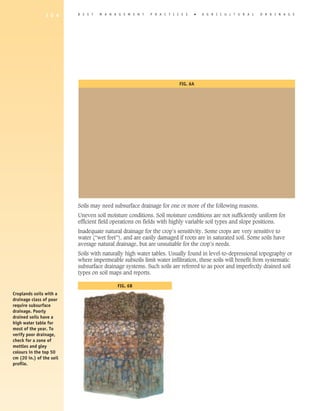
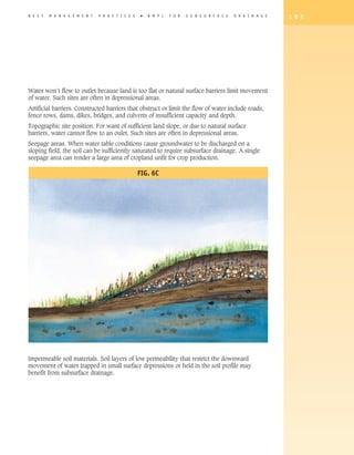
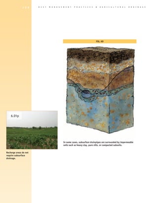
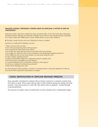
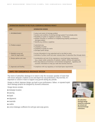
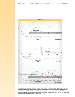
This document discusses best management practices for subsurface drainage on cropland. It begins by outlining conditions that require subsurface drainage, such as uneven soil moisture, inadequate natural drainage for certain crops, soils with high water tables, and barriers that limit water flow. Diagnosing drainage issues accurately is the first step in planning a drainage system. The document will then guide the reader through the entire process from system design to installation, maintenance, and emerging technologies. The overall goals are to manage crop inputs and contaminants, remove excess water while conserving it, manage wet areas, and protect adjacent wetlands.


![B E S T M A N A G E M E N T P R A C T I C E S � B M P s F O R S U B S U R F A C E D R A I N A G E 1 1 9
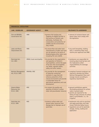
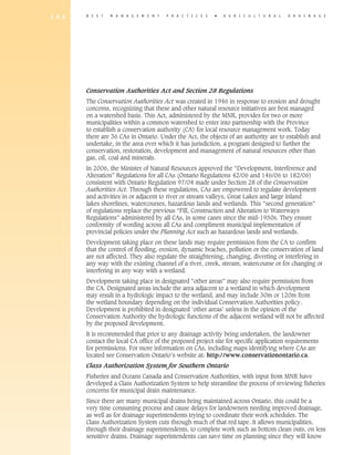
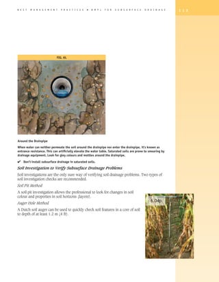
Interdependent Ecosystems at Work
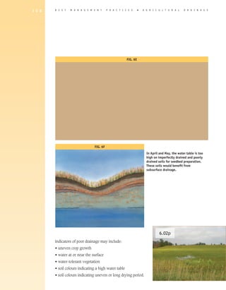
Farmers can produce high crop yield in a sustain- Fig. 6R
able way without reducing water quality. To do so,
it must be understood that the soil, and the plant
and animal life it supports, operate as an ecosys-
tem. This soil ecosystem requires that the input
elements (air, sunlight, water and soil particulars)
and plant life and animal life communities be man-
aged as an integrated system. Each one of the input
elements and living communities of that ecosystem
must be kept in balance so as to optimize the pro-
duction of any one of the components.
Cropland agriculture focuses on optimization of the
plant life community of that ecosystem. A common
input element among plant life, both above and
below the soil surface, is water originating in the
form of soil moisture.
Soil Ecosystem
Within the soil ecosystem, the percent moisture
present determines if there’s enough air to allow
eco-life (living organisms) to thrive. Eco-life breaks To be effective,
down organic matter, aids nutrient release from organic matter, and assists plants in nutrient retrieval. Large, drainage systems
healthy plants increase organic matter content in the soil. Increased organic matter contributes to moisture need to work in
retention and increased eco-life, which increases nutrient availability and the production of glues that hold soil concert with other
components together. If there’s too much or too little moisture in the soil, interactions are limited – thus plant farm production
growth and soil stability are reduced. systems – such as
nutrient management,
Plant Life Community – Crop Production soil management, and
pest management.
Moisture – too much or too little – affects each component of the soil ecosystem and the plant community or
crop production system, and each affected component can affect several others.
Example 1: Soil moisture (wet) -- results in crop disease -- results in need to re-select crop
variety or crops used in a crop rotation or in sometimes increased use of pesticides.
Example 2: Soil moisture (wet) -- increases tillage to dry soil -- reduces crop residue to
further dry soil -- soil structure is damaged -- allows more flexible weed control
program or to reduce crop root disease.[Alison to check w/Don to clarify]
If the decision is made to remove excess water with subsurface drainage, then both the soil ecosystem and the
crop production plant community changes.
Soil eco-life increases soil porosity, and if crop production management will allow the use of a practice like
no-tillage, compaction will be reduced. This in turn allows the retention of crop residue and leaves crop roots
undisturbed in the soil – which in turn allows the organic matter content of the soil to increase and the soil
structure to become more stable.
By reducing soil moisture through the installation of a drainage system, crop management practices can be
deployed to increase water infiltration and percolation – reducing the erosion of soil sediment into outlet drains,
streams, and rivers.](https://image.slidesharecdn.com/agriculturaldrainage2draft1b-120404092703-phpapp01/85/Agricultural-Drainage-23-320.jpg)
![B E S T M A N A G E M E N T P R A C T I C E S � B M P s F O R S U B S U R F A C E D R A I N A G E 1 2 1
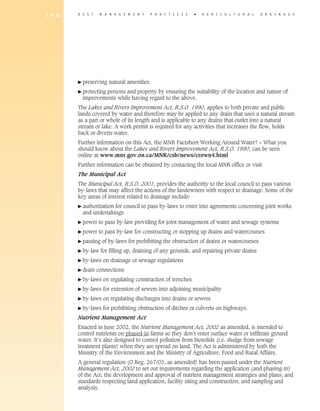
Watershed characteristics such as intended land use, soil type, and proportion of watershed
to be drained under forest cover [Alison to confirm wording] should be considered in the
selection of an appropriate drainage coefficient.
The drainage coefficient method of drainpipe design is the most common design method
used in agricultural applications
6.10p
Check the Drainage Guide for more information on drainage rate and other design ratings
based on mapped soil series.
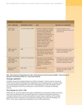
DRAINAGE DEPTh AND SPACING
Drainpipes used for 100 mm (4 in.) laterals should be deep enough to prevent damage from
tillage operations and the weight of the equipment – a minimum of 600 mm or 24 inches of
cover.
Check the Drainage Guide for recommended depth and spacing criteria related to the
individual soil series as mapped and published in regional and county soil survey reports.
Laterals' depth and spacing are linked, and should be selected jointly. Laterals must
be shallow enough to provide timely drainage, deep enough to remove excess water from
the root zone, and spaced appropriately to get uniform drainage at the soil surface. The goal
is to remove only the water that will impede proper crop growth.
Main and sub-main drains must be deep enough to provide an easy connection point and
a good outlet for lateral drains. Also, the maximum depth at which drains can be laid to
withstand trench loading varies with the width of the trench and the crushing strength of
the drainpipe to be used. Typical depths of header mains are in the range of 900–1200 mm
(36–48 in.) deep, but can be deeper as dictated by topography. A header main is there for
the primary purpose of transporting water to the outlet
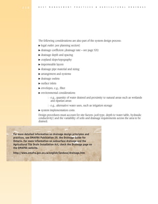
IMPERMEABLE LAyERS
The influence of an impermeable layer on the behaviour of a groundwater table depends
on its depth below the level of drainpipe and on the drainpipe spacing. The flow pattern
and rate of the water moving toward the drain can be altered drastically by an impermeable
layer (such as dense, compacted, or heavier subsoil).
Most drainpipe spacing in Ontario is close enough together not to be affected by the
impermeable layer as long as the drainpipe is installed above it. Where the drainpipe needs
to be installed in the impermeable layer in order to get adequate depth and cover, the
impermeable layer can have a major affect. Regardless of the soil above the impermeable
layer, the rate of water movement to the drainpipe is greatly controlled by the impermeable
layer.
There are various options available to overcome this problem – each with a cost associated
with it. It is best to consult with a licensed drainage contractor or experienced drainage
designer for options. Each situation is unique. In some cases, a decision may need to be
made whether subdrainage will be effective at all.](https://image.slidesharecdn.com/agriculturaldrainage2draft1b-120404092703-phpapp01/85/Agricultural-Drainage-25-320.jpg)
![1 2 2 B E S T M A N A G E M E N T P R A C T I C E S � A gricultural D R A I N A G E
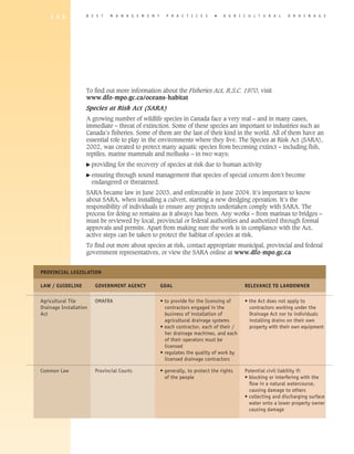
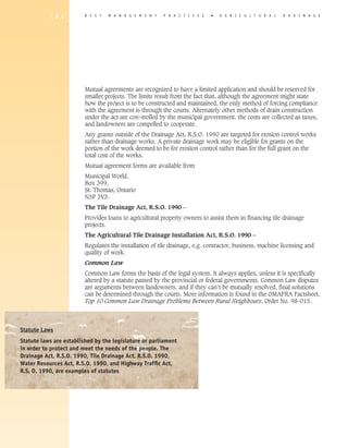
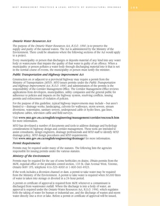
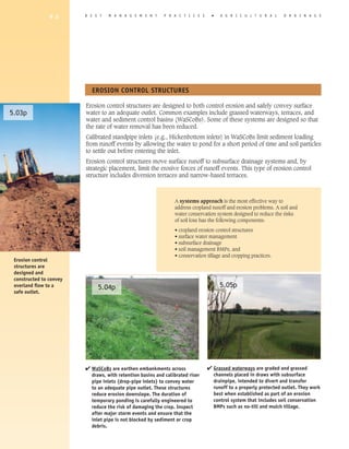
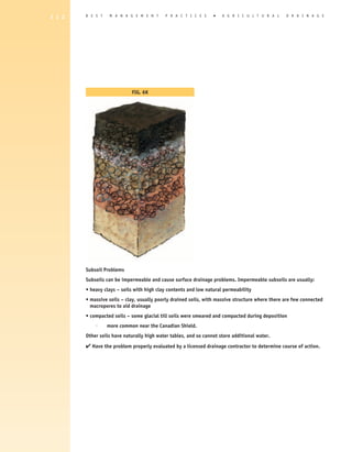
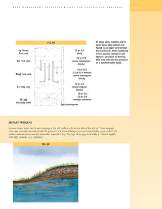
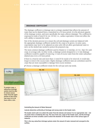
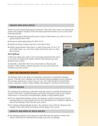
Fig. 6T
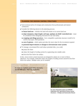
When impermeable layers are encountered, the pipes need to be placed closer together to achieve the
effect they would have in a deep permeable soil. However, if the depth of the impermeable layer below
pipe level exceeds a fourth of the drain spacing, the flow system can be treated as if such a layer were
absent.
Drainpipe and Sizing
The maximum amount of water a drainage pipe can carry (its flow capacity) depends on
the drainpipe's inside diameter, the installation grade, and the inside drainpipe surface
roughness.
In the farm drainage industry, a more common way of reflecting drainage pipe capacity
is the number of acres that can be drained through a particular diameter of drainage pipe.
[Alison to get clarification on length/spacing vis-a-vis no. of acres]](https://image.slidesharecdn.com/agriculturaldrainage2draft1b-120404092703-phpapp01/85/Agricultural-Drainage-26-320.jpg)

![B E S T M A N A G E M E N T P R A C T I C E S � B M P s F O R S U B S U R F A C E D R A I N A G E 1 2 9
Ochre, an iron oxide, affects about 2% of drainage systems in Ontario. It occurs in two soil
conditions: acidic sands and poorly drained sands.
Ochre accumulates through chemical or microbiological processes, or both. It’s a natural
condition usually found where new land – sandy in nature with high organic matter – is
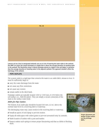
cleared and drained. Recognized by brilliant red deposits at drain outfalls, iron ochre can
seal drain openings very quickly.
At present there are no long-term solutions. If you encounter ochre:
� plan to replace or abandon the original system when it fails
� flush drainpipe with high-pressure water to provide temporary relief.
Connecting Old Drainage System to New System
If existing lateral pipes are relatively new, clean and not full of sediment, they are probably
working. They can be hooked into new drainpipe.
However, if they are full of sediment, then relieve [Alison to clarify] with crushed stone. Do
not directly connect the two systems, as the old system may add excessive sediment to the
new installation.
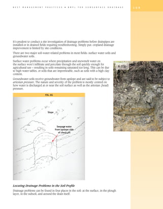
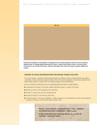
Seepage Control
Broad, flat areas that are wet due to seepage from adjoining highlands, springs, seepage
lines at two different layers of soil etc. can benefit from interception drains.
Interception drains are installed at right angles to the flow of groundwater to intercept
subsurface flows.](https://image.slidesharecdn.com/agriculturaldrainage2draft1b-120404092703-phpapp01/85/Agricultural-Drainage-33-320.jpg)
![1 3 2 B E S T M A N A G E M E N T P R A C T I C E S � A gricultural D R A I N A G E
4 etermine whether a satisfactory outlet is available for the proposed work on the your
d
property
4 f not, negotiate agreements, in writing, with neighbours and other parties to obtain
i
authority to enter their property [add: in order to access outlet?]
4 f this does not work out, consider a petition for a municipal drain under the Drainage Act
i
– see section 7.
4 heck with your local CA regarding regulatory requirements, e.g., Clean Water
C
Act, Conservation Authorities Act -- source water protection, section 28, localized
requirements or restrictions
4 isit the municipal office to ensure municipal drain requirements will be met. [add more
V
detail?]
4 Ensure financing is in place to complete the project.
4 Locate existing drainage plans of the farm.
4 Obtain a plan for the entire farm, even though only a part is to be drained.
4 lan with consideration for drainage of upslope watersheds or neighbouring farms’
P
drainage flow.
4 Ensure the contractor is aware of the location and existence of gas and oil lines,
telephone lines, hydro lines, water lines, and septic beds. In other words, over and above
knowledge of your own utilities – “Call before you dig.”
4 Arrange mutual agreements and easements (hydro and other utilities) in advance. [add
more detail?]
4 Ensure that the contractor is aware of the location of manure storages and transfer
systems so that requirements for distance separation under the Nutrient Management Act
can be accounted for when designing the drainage system.
4 Discuss the removal and/or repair of fencing and access of livestock to the work area, or
any other on-farm practices that the contractor should know about.
4 Point out the location of existing subsurface drains to the contractor.
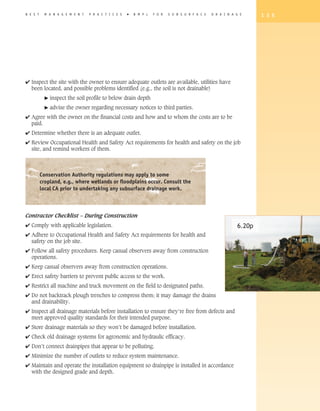
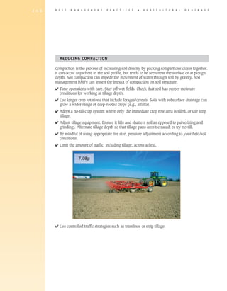
4 o avoid the risk of soil compaction, install drains in the summer or fall whenever
T
possible
� c
rop damage can be as little as 10% when drains are constructed with care
through crops
� m
ake use of strategic crop rotation planning, e.g., field to be drained is planted in
wheat or hay
� c
onstruction should be in reasonably dry soil so its structure is not destroyed and
drainability impaired – if the field is dry enough to work, it’s dry enough to install
drains.](https://image.slidesharecdn.com/agriculturaldrainage2draft1b-120404092703-phpapp01/85/Agricultural-Drainage-36-320.jpg)
![B E S T M A N A G E M E N T P R A C T I C E S � B M P s F O R S U B S U R F A C E D R A I N A G E 1 4 1
6.27p 6.28p
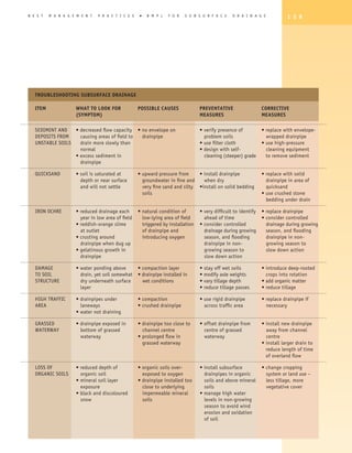
As with pipe outlets and surface inlets, regular If existing lateral drainpipes are relatively new,
inspections are an excellent early-warning system to clean and not full of sediment, they are probably
help you troubleshoot. working. They can be hooked into new drainpipe –
once you verify they are working properly. however,
if existing drainpipes are full of sediment, then
relieve with crushed stone. Do not directly connect
the two systems, as the old system may add excessive
sediment.
6.29p When drains are being installed, ensure you’re not
hooking up to existing drains that may be a source of
pollutant / wastewater. No direct or illegal hookups.
[Alison to clarify] Also respect separation distances.
6.30p
6.31p](https://image.slidesharecdn.com/agriculturaldrainage2draft1b-120404092703-phpapp01/85/Agricultural-Drainage-45-320.jpg)
![B E S T M A N A G E M E N T P R A C T I C E S � B M P s T H A T C O M P L E M E N T C R O P L A N D D R A I N A G E 1 5 1
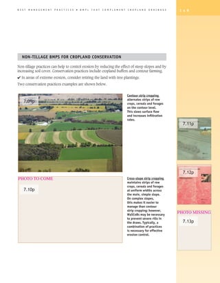
4 Don’t spread if any of the following conditions is present:
� rainfall occurs shortly before application
� heavy rains are forecast within 12–24 hours of spreading on cropland with
subsurface drainage
� ground is frozen and/or snow-covered.
7.15p
4 Incorporate manure when and where there is risk for soil erosion.
4 Develop a monitoring and contingency plan for manure application.
React immediately to spills and leaks. This will reduce the risk of
manure entering the agricultural drainage system.
Prepare spills
contingency plans
7.16p and communicate
them to staff and
family members.
Monitor pipe outlets
after applying liquid
manure.
7.17p
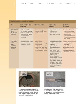
BMPS FOR LIqUID MANURE AND BIOSOLIDS ON CROPLAND WITh SUBSURFACE DRAINAGE:
4 use control valves for transfer of liquid manure from storage to field, where feasible, to
shut off the system if a manure leak is detected
4 use inspection chambers on subsurface drains at farm lot lines so that you can see and 7.19p
take samples of subsurface drain water [Alison to check re: John’s comment]
4 ensure milking centre washwater treatment systems or household septic systems are not 7.18p
connected to field subsurface drainage systems – this practice is illegal!
4 create a contingency plans for spills – specify what to do if a problem arises, who to
contact, etc.
4 set up a visual inspection schedule of subsurface drains e.g. spring, fall, after major
For more information on
storm events, during spreading of liquid manure etc .
nutrient management,
� keep written record of observations – if contaminants are suspected, please see the Best
implement your contingency plan Management Practices
books, 5.61p Managing
4 ensure outlet areas are not subject to scouring with erosion – protect with filter cloth and Crop Nutrients, 5.62p
rock rip-rap where necessary
Manure Management
and 5.63p Nutrient
Management Planning.](https://image.slidesharecdn.com/agriculturaldrainage2draft1b-120404092703-phpapp01/85/Agricultural-Drainage-55-320.jpg)
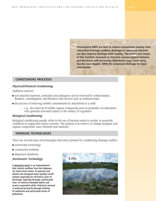
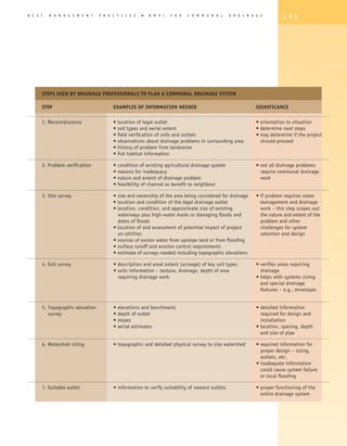
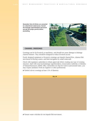
![B E S T M A N A G E M E N T P R A C T I C E S � B M P s F O R C O M M U N A L D R A I N A G E 1 6 7
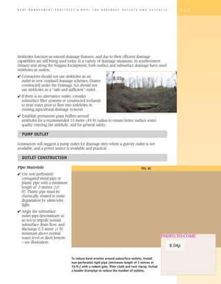
Most municipal drains constructed under the Drainage Act are either open drains (ditches)
or closed drains (large-diameter drainpipe). They can also include structures such as dikes
or berms, pumping stations, buffer strips, grassed waterways, stormwater
detention ponds, culverts and bridges. Some creeks and small rivers have PHOTO TO COME
been incorporated as municipal drains.
9.06p
To minimize the potential negative impacts on natural watercourses,
sometimes a natural watercourse is incorporated as a municipal drain
strictly for the purpose of removing beaver dams and other obstructions. No
channelization work is involved.
A municipal drain can also include a water control structure. Some water
control structures are being fitted into existing municipal drains for the
purpose of retaining water and even restoring or enhancing wetlands. [For
more info, see wetland drain restoration project, page XX.]
Some large rivers
DESIGNING A NEW OR IMPROVED CONSTRUCTED DRAIN PROJECT such as the South
Branch of the Nation,
If this is a big enough project, there are many factors for drainage professionals to consider. and portions of the
Raisin and Saugeen
Design Considerations are channels under
the Drainage Act.
The design should consider the following: 9.07p
� order: peak flow, flooding, scouring, low-
level flow, etc.
� peak-flow rates in outlet watercourse that
won’t be increased from pre-construction 9.08p
conditions after the project is completed
� ability to handle volume and flow-rate
capacity of a 1 in 2-year design storm
frequency
� prevention of increased flooding downstream
� flood control measures downstream where 9.09p
warranted.
� minimal ditch-bank scouring and slumping
� effective sediment transport
� low-level flow that allows outlets to discharge
� prevention of soil saturation and flooding. Closed communal
drains are often
constructed with
oversized pipe to
accommodate future
additions to the
acreage outlet.](https://image.slidesharecdn.com/agriculturaldrainage2draft1b-120404092703-phpapp01/85/Agricultural-Drainage-71-320.jpg)
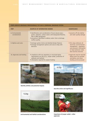
![1 6 8 B E S T M A N A G E M E N T P R A C T I C E S � A gricultural D R A I N A G E
Hydraulic Design: Hydraulic Grade Line
The hydraulic grade line is the actual water surface profile in the designed channel at the
design flow. The first step is to determine the highest allowable hydraulic grade line.
Control points are established to drain cropland, allow for surface runoff from surface
drainage features, as well as elevations of bridges, culverts and roads. The maximum
hydraulic grade line is drawn through or below as many control points as possible to
minimize flooding
Fig. 9A
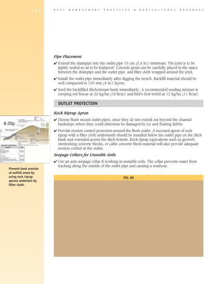
Bottom Grade and Depth of Ditch
The ditch bottom should be deep enough to allow outlets to discharge above the low-flow
elevation: 0.3–0.5 metre (1–1.6 ft) above the ditch bottom. Also:
� m
inimum depth for ditches with outlets is 1.5 m (5 ft) [Fig. 9B (was 5.R illustration
x-section of ditch]
� ufficient
s depth is provided for some sediment build-up – this will prevent early
sedimentation as an obstacle to flow
t
arget to have sufficient depth so that the outlet pipe is at or above normal flow of
water – preferably 0.3 m (1 ft) above
� rades
g and depths of pipe from the lowest drainable depression in the watershed to
the outlet for the drainage channel must be aligned to determine minimum ditch depth
throughout the project.](https://image.slidesharecdn.com/agriculturaldrainage2draft1b-120404092703-phpapp01/85/Agricultural-Drainage-72-320.jpg)
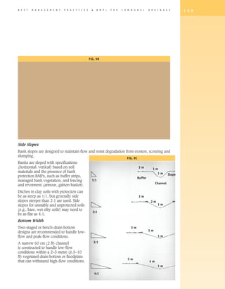

![B E S T M A N A G E M E N T P R A C T I C E S � B M P s F O R C O M M U N A L D R A I N A G E 1 7 1
CONSTRUCTING COMMUNAL DRAINAGE ChANNELS
During ditch construction, the potential risk to the environment is greater. Sediment from
excavation, bare banks, and adjacent lands can become deposited in the channel, impairing
water quality and habitat. Drainage professionals and contractors must ensure that sediment
control is addressed in the timing, planning and construction of the drainage channel.
4 Schedule drain construction or improvement work during the summer following the
harvest of cereals in rotation to reduce sedimentation and habitat disturbance. per Don
Lobb, cross-ref w/Timing of Maintenance Activities]
After considering downstream impacts, select one or more of the following BMPs that suit
your circumstances.
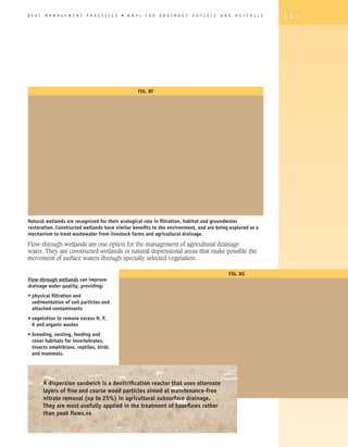
Buffer strips keep agricultural activities and water separated. They reduce the need
for clean-out maintenance of drains They can also reduce runoff, filter contaminants,
act as windbreaks, be harvested as forage, provide shade (which in turn cools water
temperatures), and provide habitat for a variety of species.
Long-Term Protection
4 Establish buffer strips (for more
information, see pages XX–XX). Consult Be cautious. With buffer strips, build it and they will come. The
with your local Conservation Authority issue of wildlife predation may have to be addressed.
or Ministry of Natural Resources office
to identify the most appropriate timing
window for construction, to protect fish and
wildlife.
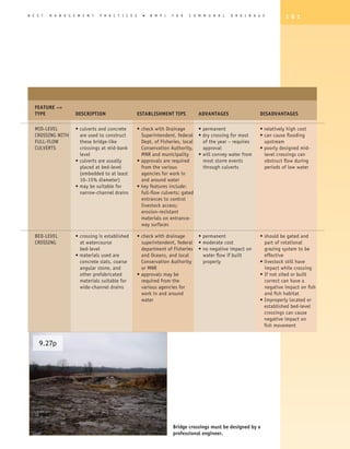
Short-Term During Construction 9.10p
4 Use mulching and silt (turbidity) fences:
� mulching can provide temporary protection of ditch banks from erosion
during or immediately following construction
�a wide range of natural and synthetic mulching materials is available
� seed–mulch mixes used in road construction are also effective
� turbidity fence and rock check dams.](https://image.slidesharecdn.com/agriculturaldrainage2draft1b-120404092703-phpapp01/85/Agricultural-Drainage-75-320.jpg)
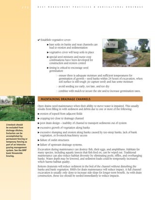
![B E S T M A N A G E M E N T P R A C T I C E S � B M P s F O R C O M M U N A L D R A I N A G E 1 7 3
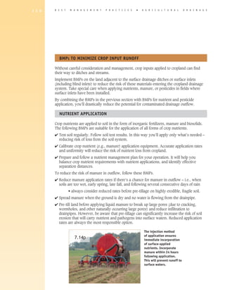
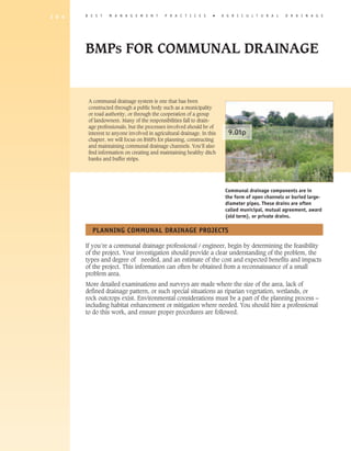
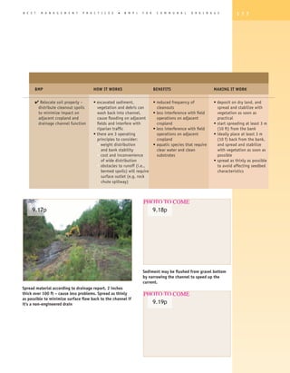
Sediment, excessive vegetation,
and woody debris at the bottom
9.13p of the channel may obstruct flow
excessively. Remove it during the
early part of the growing season
(June) where possible to minimize
disturbance. Bottom cleanouts will
only remove the obstructions in the
channel bed. Bank stability is not
affected. Removed sediment should
be spread well back from the top of
the ditch bank.
Vegetation and crop residue
can block the flow of draining
water during times of high flow. 9.14p
Removing large obstructions can
stabilize the banks. This involves
the judicious removal of woody
vegetation by trimming, pruning
and thinning, or mowing only
heavily grassed areas. Removal from
only one side of the ditch bank may
be all that’s necessary.
Other [open?] drainage channels tend to naturalize over time. The naturalization process
results in:
� changes in the channel’s shape, which increases habitat diversity
� increased plant diversity on the banks
� increased shade and cover provided by bank vegetation
� increased numbers of aquatic plants.
Many species of fish and wildlife that require
clean water and substrates benefit from good
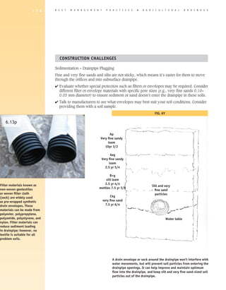
drain maintenance. And remember that When planting trees, take care that the tree species you select
conservation cropping, establishing buffers
will not interfere with future maintenance activities, won’t
between cropped fields and drainage channels,
drop undue debris, and that trees comply with engineer’s
and planting shade trees along drainage
channels will go a long way to reducing future report if it’s a municipal drain.
drain maintenance requirements and improving
habitats for a range of species.](https://image.slidesharecdn.com/agriculturaldrainage2draft1b-120404092703-phpapp01/85/Agricultural-Drainage-77-320.jpg)
![1 7 6 B E S T M A N A G E M E N T P R A C T I C E S � A gricultural D R A I N A G E
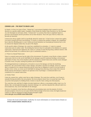
BMP HOW IT WORKS BENEFITS MAKING IT WORK
4 Time maintenance • early season maintenance • properly timed maintenance • do maintenance early in the
activities – schedule will help disturbed bank can decrease costs growing season to allow
drainage work to maximize vegetation re-establish • all fish and wildlife species, more time for regrowth of
effectiveness while • alternatively, maintaining if maintenance is well-timed vegetation
minimizing impact on drains when water flow is [per Don Lobb, cross-ref w/
drain habitat low will disturb less Timing of Maintenance
vegetation, banks and Activities]
habitat • do it in as short a period
• there are critical periods in as possible
the year for spawning, • maintain drains when flows
nesting and hibernation – are low
avoiding these times will • avoid critical times for fish,
help with species survival amphibians, birds and
reptiles
4 Remove debris and excess • excess debris/ vegetation • improved drain function • remove debris and
vegetation from bottom of on drain bottom can • less sediment buildup and vegetation if heavy siltation
drainage channel – obstruct flow, trap sediment reduced need for drain exists and flushing are
manual or mechanical and create barriers to fish maintenance required
removal of vegetation and • fish species requiring clean • create a two-stage channel:
debris from channel bed substrates and barrier-free excavate or cut a narrow
mobility c
hannel through bottom
vegetation (especially
cattails); water flow may be
sufficient to keep open
4 Perform bottom cleanout • most obstacles to flow and • increased efficiency of • practise good sediment
vs full drain cleanout – drain function are in the cleanout work control techniques during
excavate or cut a narrow bottom of the channel • less excavated material to cleanout
channel through • restricting cleanouts to the manage • incorporate natural-channel
vegetation and sediment drain bottom will allow: • reduced fossil fuel features into drains during
at bottom of drain water to flow, undisturbed consumption bottom cleanouts to benefit
bank vegetation to • many fish and wildlife fish and reduce erosion/
assimilate nutrients and species, because bottom sedimentation and bank
sediment, and aquatic cleanouts provide superior failures
habitats to function with protection of habitats than
minimal disturbance full drain cleanouts](https://image.slidesharecdn.com/agriculturaldrainage2draft1b-120404092703-phpapp01/85/Agricultural-Drainage-80-320.jpg)
![1 7 8 B E S T M A N A G E M E N T P R A C T I C E S � A G R I C U L T U R A L D R A I N A G E
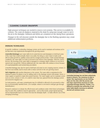
BEAVER DAM REMOVAL
Beaver dams need to be removed or breached periodically to avoid the flooding of private
and public land. Removal is normally handled by professionals and is accomplished using
hand tools or equipment such as backhoes. However, the removal of beaver dams can have
a negative impact on fish and fish habitat and on downstream flows. Consider impacts on
hibernating animals.
4 Before undertaking this work, notify your local Conservation Authority or Fisheries and
Ocean Canada office. For more information, see the “Beaver Dam Removal” operational
statement produced by Fisheries and Oceans Canada.
4 Beaver bafflers and similar techniques that maintain the dam but lower ponds and
maintain flow are not recommended for municipal drains.
4 Hire a licensed trapper to remove beaver. Consider live trapping and release.
For more information, see the recent guidelines on drain maintenance developed by the
Ministry of Natural Resources, OMAFRA, and the Drainage Superintendents Association of
Ontario. (MNR Guide to Understand and Coping with Beaver Activities” FG-006.) [insert
reference]
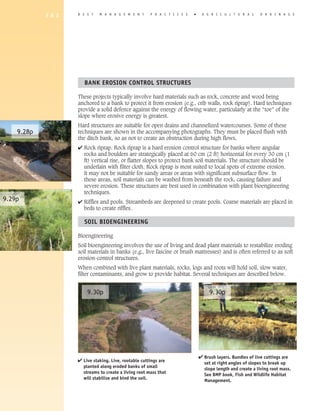
The key BMPs for beaver removal
include contacting the proper
9.20p authorities and, where appropriate,
hiring a professional to handle the task.
This approach will reduce the risk of
causing damage downstream.
BMPS FOR DITCh BANKS AND BUFFER STRIPS
Some ditch banks are subject to slumping, scouring, and other forms of bank erosion.
Observe the integrity of ditch banks seasonally, and take timely action when need so as to
reduce downstream sedimentation and early drain cleanout maintenance.
Before you start
4 Verify the problem. Determine the type of bank 9.21p
erosion, e.g., stream or subsurface flow. Decide
what’s caused the erosion.
Inspect the integrity of on-farm and
communal ditch banks each spring and
after severe rainfall events.](https://image.slidesharecdn.com/agriculturaldrainage2draft1b-120404092703-phpapp01/85/Agricultural-Drainage-82-320.jpg)
![1 8 4 B E S T M A N A G E M E N T P R A C T I C E S � A G R I C U L T U R A L D R A I N A G E
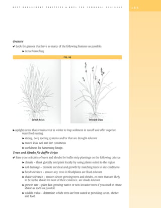
BUFFER STRIPS
Buffer strips come in all shapes and sizes, and for good reason. Wider buffers are
advantageous for wildlife habitats, whereas narrow buffers are perfectly adequate for simple
setbacks from cropland. Local site conditions also affect buffer strip design. Wider buffers are
more effective for runoff and erosion control on steeply sloping lands.,
Generally speaking:
4 grassed buffers should be at least 3 metres (10 ft), wide but 5 metres is more effective
[see BMP Buffer Strips]
4 consider designs that serve multiple uses: e.g., erosion control, filters for runoff, wildlife
habitat, biodiversity, field access and forestry
4 municipal drains can be treed – but preferably
on south and west side – assuming 9.38p
accommodation has been made for
maintenance
� check Drainage Report for tree
planting details
� thedrainage superintendent must
be consulted and approval obtained
before altering or replanting
4 drop structures and berms may be
appropriate where field runoff regularly flows
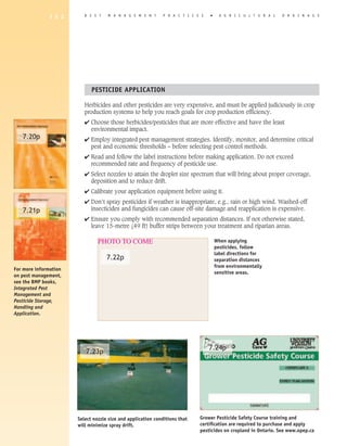
in a draw before it reaches the ditch. Routinely inspect buffers strips along drains
and other outlets. Look for areas where
4 Plan and implement the most suitable design concentrated overland flow has bypassed your
to meet the desired functions for the riparian buffers (e.g., for “short-circuiting” overland
condition and your preferences. This is key to flow).
a successful riparian buffer.
Buffer strips can be planted to grass, wildflowers, shrubs and trees.
4 Select plants according to the desired buffer function and also the plants’ suitability to
local site conditions, including climate, soil, soil drainage, soil pH and risk of flooding.
Avoid invasive, non-native species, wherever possible.
Plants can be established in many arrangements and mixtures to suit design needs. Suitable
species for buffer strip plantings are grouped and listed below.](https://image.slidesharecdn.com/agriculturaldrainage2draft1b-120404092703-phpapp01/85/Agricultural-Drainage-88-320.jpg)
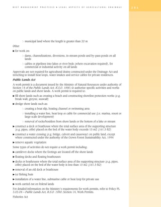
![B E S T M A N A G E M E N T P R A C T I C E S � B M P s F O R C O M M U N A L D R A I N A G E 1 8 7
where necessary. Create an action plan: outline your resources, your
time, and a schedule of activities. Remember that the project can be 9.39p
phased in over several years. [scan of Buffer Strip book. see BMP Buffer
Strips for designs]
Step #6 Maintain, monitor and evaluate. Maintain planted vegetation by
irrigating until plants are have become established.
Confirm survival rates of planted grasses, shrubs and trees. Look for
washouts and rills cutting across buffer strip, as well as sedimentation
building up the buffer strip which may eventually create a berm.
Determine if the project is fulfilling its intended functions. Assess whether
additional BMPs would improve its effectiveness.
Consult with your
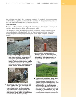
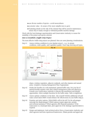
FIG. #35
local Conservation
Authority to discuss
risk assessment
and identify
opportunities.
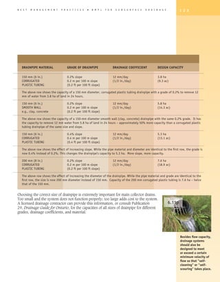
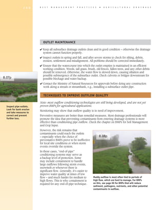
On the left is the “before” sketch. On the right is the planned projects sketch for an on-farm stream bank
area.
Cropland erosion is evident from the sloping field on the left of the stream and bank degradation from
intensive livestock access is noted on the right side of the stream. Soil and water conservation measures
– including a cropland buffer strip – are planned for the sloping field. Intensive grazing management,
fencing and alternate water sources are planned for the streamside grazing area.
Narrow buffer strip
9.41p designs are most suitable
along communal drainage 9.43p
channels.
Wide, shallow and
channelized streams
will become narrower
after buffer strips are
established.](https://image.slidesharecdn.com/agriculturaldrainage2draft1b-120404092703-phpapp01/85/Agricultural-Drainage-91-320.jpg)