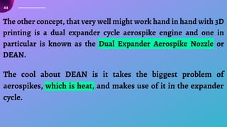
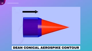
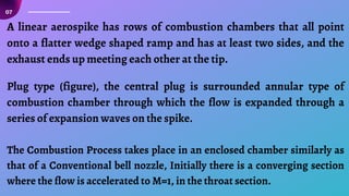
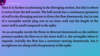
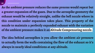
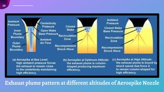
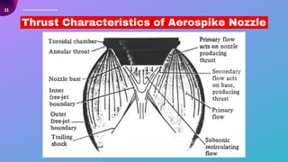
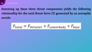
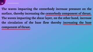
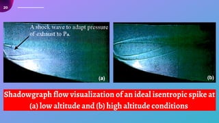
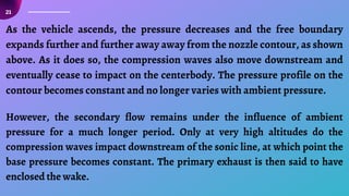
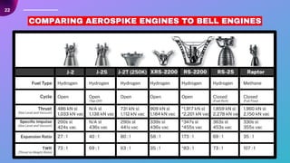
The document discusses the advantages of aerospike nozzles over traditional De Laval nozzles in rocket engines, particularly for single-stage-to-orbit (SSTO) vehicles. Aerospike nozzles provide consistent efficiency across varying altitudes by allowing for altitude compensation, which mitigates performance losses seen in conventional nozzles. The piece also highlights the challenges and complexities surrounding aerospike technology, including heat management, manufacturing costs, and a lack of flight experience.


![37
THRUST VECTORING
THRUST VECTORING
THRUST VECTORING
Because the combustion chambers can be controlled individually, the vehicle
can be maneuvered using differential thrust vectoring. This eliminates the
need for the heavy gimbals and actuators used to vary the direction of
traditional nozzles.
AEROSPIKE THRUST VECTORING CONTROL [FROM ROCKETDYNE, 1999]
AEROSPIKE THRUST VECTORING CONTROL [FROM ROCKETDYNE, 1999]
AEROSPIKE THRUST VECTORING CONTROL [FROM ROCKETDYNE, 1999]](https://image.slidesharecdn.com/aerospikeengine-221127144509-20717c91/85/Aerospike-Engine-pdf-37-320.jpg)
![38
The figure shows the proposed experimental SLV (Space Launch Vehicle) X-33 ,
as shown the aerospike is positioned inside the base portion of the SLV which
reduces a type of drag known as base drag.
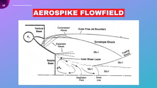
LOWER VEHICLE DRAG
LOWER VEHICLE DRAG
LOWER VEHICLE DRAG
AEROSPIKE NOZZLES INSTALLED
AEROSPIKE NOZZLES INSTALLED
AEROSPIKE NOZZLES INSTALLED
ON X-33[ROCKETDYNE, 1999]
ON X-33[ROCKETDYNE, 1999]
ON X-33[ROCKETDYNE, 1999]](https://image.slidesharecdn.com/aerospikeengine-221127144509-20717c91/85/Aerospike-Engine-pdf-38-320.jpg)