1. 1/11
E. Höfler Innovation description October 2013
Vertical tubular hydraulic turbine with mixed-flow type runner
DESCRIPTION
Presented innovation interfere in the field of Francis turbines of high specific speed, which have long
been established and generally used the turbine concept, consisting of spiral casing, stay ring, cylindrical
wicket gates and radial-axial Francis type runner. Our achievement has developed alternative, involving
the inlet elbow, stay ring with supporting ribs by minimal impact on the flow, conical wicket gates as a
regulating apparatus and new type of semi-axial runner. Novelty is also the draft cone, having a circular
inlet cross section (just below the runner), an elliptical cross-sectional outlet and inclined axis in addition.
The outflow part of the turbine flow passage is conventional.
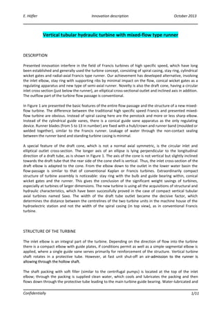
In Figure 1 are presented the basic features of the entire flow passage and the structure of a new mixed-
flow turbine. The difference between the traditional high specific speed Francis and presented mixed-
flow turbine are obvious. Instead of spiral casing here are the penstock and more or less sharp elbow.
Instead of the cylindrical guide vanes, there is a conical guide vane apparatus as the only regulating
device. Runner blades (from 5 to 13 in number) are fixed with a hub/crown and runner band (moulded or
welded together), similar to the Francis runner. Leakage of water through the non-contact sealing
between the runner band and standing turbine casing is minimal.
A special feature of the draft cone, which is not a normal axial symmetric, is the circular inlet and
elliptical outlet cross-section. The longer axis of an ellipse is lying perpendicular to the longitudinal
direction of a draft tube, as is shown in Figure 1. The axis of the cone is not vertical but slightly inclined
towards the draft tube that the rear side of the cone shell is vertical. Thus, the inlet cross-section of the
draft elbow is adapted to the cone. From the elbow down to the outlet in the lower water basin the
flow-passage is similar to that of conventional Kaplan or Francis turbines. Extraordinarily compact
structure of turbine assembly is noticeable: stay ring with the bulb and guide bearing within, conical
wicket gates and the runner. This gives the conclusion of the significant weight savings of turbines,
especially at turbines of larger dimensions. The new turbine is using all the acquisitions of structural and
hydraulic characteristics, which have been successfully proved in the case of compact vertical tubular
axial turbines named Saxo. The width of the draft tube outlet became the decisive factor, which
determines the distance between the centrelines of the two turbine units in the machine house of the
hydroelectric station and not the width of the spiral casing (in top view), as in conventional Francis
turbine.
STRUCTURE OF THE TURBINE
The inlet elbow is an integral part of the turbine. Depending on the direction of flow into the turbine
there is a compact elbow with guide plates, if conditions permit as well as a simple segmental elbow is
applied, where a single guide vane serves primarily for reinforcement of the structure. Vertical turbine
shaft rotates in a protective tube. However, at fast unit shut-off an air-admission to the runner isir-admission to the runner is
allowing through the hollow shaft.allowing through the hollow shaft.
The shaft packing with soft filler (similar to the centrifugal pumps) is located at the top of the inlet
elbow; through the packing is supplied clean water, which cools and lubricates the packing and then
flows down through the protective tube leading to the main turbine guide bearing. Water-lubricated and
Confidentially
2. 2/11
E. Höfler Innovation description October 2013
cooled guide bearing – located above the turbine runner – is one of the major acquisitions of a new
turbine concept. Material of the bearing shells can be moulded polymer, PTFE (commercial name Teflon)
with additives or sintered metal based on bronze. By choosing such a bearing is solved concerns with oil
or grease, the sealing of casing against the rotating shaft is simple, and finally, between the hub casing
and the runner the labyrinth sealing is sufficient. This is a contribution to maintaining a clean
environment. The system of lubricating-sealing water should be carefully designed (filtering, maintaining
pressure and flow), because the inflow of the unclean water from the turbine passage should be
prevented also when the turbine is not operating.
The next benefit of a new turbine is its rigid structure and alignment of the vertical turbine shaft. In
turbines with low speed of rotation, it is possible to attach a heavy multi-pole electric generator with
high flywheel effect. The generator can be placed at the top of the inlet elbow casing. However, it is
better to fix generator anchoring to the concrete block built around the turbine. The lower (bottom)
bearing of the generator serves as the second turbine guide bearing, while the generator trust (axial)
bearing takes the turbine axial loading as well.
REVIEW OF INFORMATION
To best of authors’ knowledge, the review of available relevant world literature and other information
shows that the presented innovation so far has not been worked, not even as a concept, no model or
prototype has been developed nor has been the subject of theoretical investigation. The material of a
course organised annually by the school EPFL and the laboratory LMH in Switzerland, it can be
considered as a worldwide reference in water-turbine industry, does not mention the proposed
assembly of turbine components. Even the most about similar solutions can be found in the original
Russian literature or later translated into English. With respect to the mixed-flow turbine, one can find
the most known double regulated so-called Deriaz type turbine, often intended for pump-turbines, as
well as single regulated machines with fixed runner blades; all, however, by spiral casing and cylindrical
or conical wicket gates.
Figure 2 shows what falls under the internationally harmonized use of the term "Diagonal machines with
fixed runner blades". Meridional contour of the runner channel must be guided by whether there are
adjustable runner blades - Deriaz type runner - or they are firmly assembled with the runner hub (and
runner band), as is it the case at proposed mixed-flow runner. In new turbine the meridional contour can
follow the rule of maximum possible curve radius, which is optimal from the standpoint of smooth flow.
In turbine type Deriaz the meridional contour of the runner channel has to be adapted to the adjustable
blades and the optimal contour cannot be approached.
PRESENTATION OF THE ENTIRE TURBINE UNIT
In Figures 3 and 4 are presented the the basic features of the entire flow passage and the structure of
mixed-flow turbine unit (without generator and auxiliary systems). Shown turbine study-case has a
runner of 2000 mm in outlet diameter, which is rotating at 375 r.p.m. These two data corresponds to the
operating range of the discharge of 18 to 41 m3
/s and turbine net head in about 41 to 48 metres, which
gives maximum turbine power of 16 MW. In Figures 3 and 4 is shown which parts of the turbine are
definitively surrounded with concrete and which parts are accessible to subsequent dismounting and
maintenance.
Confidentially
3. 3/11
E. Höfler Innovation description October 2013
Figure 5 shows the details of the turbine stay ring, conical wicket gates and the runner, which are in fact
the core of the presented innovation together with a specific form of draft cone. Draft cone is symmetric
only considering vertically cross-sectional plain alongside draft tube.
FIELD OF APPLICATION
A theoretical model was developed to calculate the region of optimal operation of new mixed-flow
turbine. Results are confirming that the new turbine with a certain prescribed flow-passage system is
capable of covering a relatively broad transition range between conventional Francis and Kaplan
turbines. The so-called CORDIER diagram, presented in Figure 6, provides an overview on the field of
application of the proposed mixed-flow turbine, comparing with statistical data for Francis and Kaplan
turbine types. As regards the hydraulic design, it is estimated that the entire field of a new turbines may
be covered by one water passage shape and two hydraulically different runner blades.
Furthermore, within the scope of the mixed-flow turbine development and research, the CFD simulation
of the real fluid flow through the entire turbine passage was carried out. The data of such virtual turbine
are as follows: a reference, i.e. the outlet diameter of the runner is one meter, the runner rotates with
420 r.p.m. and it is fitted with a set of blades designed for low-specific speed range of application. As a
result of the simulation the discharge - energy hill chart is shown in Figure 7. This here confirms all the
predicted features and all-over performance of the new mixed-flow turbine.
BASIC QUANTITIES DESCRIBING TURBINE OPERATION POINT
Q [m3
/s] volume flow rate
Hn [ m ] turbine net head
D2 [ m ] runner outlet diameter
n [min-1
] turbine speed of rotation
g [m/s2
] gravity acceleration
ω [rad/s] runner angular velocity
Discharge coefficient: 2 3
2
4
(n/60)
Q
D
ϕ
π
= [ – ]
Energy coefficient: 2 2 2
2
2
( / 60)
ngH
D n
ψ
π
= [ – ]
Dimensionless specific speed:
1/2 1/2
3/4 3/4
( / )
(2 )
s
n
Q
gH
π ϕ
ν ω
ψ
= = [ – ]
Dimensionless diameter number:
1/4 1/4
2
1/2 1/2
(2 )
2( / )
n
s
D gH
Q
ψ
δ
π ϕ
= = [ – ]
Confidentially
4. 4/11
E. Höfler Innovation description October 2013
Alternative specific speed:
1/2
3/4
157.8q s
n
Q
n n
H
ν= = [min-1
]
ECONOMIC BENEFITS
Economic benefits of the innovation shall be based on the following:
• Mixed-flow turbine enables extremely compact design and therefore brings savings in weight of
a turbine
• Reduced extent of civil works and abridged period of erection
• In comparison to the Francis-type units of the same operating data, a new turbine requires
smaller machine-house, whose advantage is particularly found in hydro-stations with large
number of units
• Short time of installation in the field, thanks to technology, that some modules may finally be
assembled and tested at the works and then transported to the field
• High level of efficiency in a broad range of operation, taking into account a single regulated
turbine
The benefits are estimated to be from 8 to 15% of lower costs of investment (per typical and standard
hydro plant) and of lower operational cost from 5 to 10% (derive from initial lower investment costs that
are represented as depreciation costs).
On the basis of existing research may be provided that mixed-flow turbine within a look of efficiency is
equivalent to conventional Francis type solution at least.
SUMMARY
An assembly of conical wicket gates and a mixed-flow type runner with fixed blades, followed by
asymmetrical draft cone represents an innovation.
Extensive hydraulic tests of a model have to be the next step of a new turbine development.Extensive hydraulic tests of a model have to be the next step of a new turbine development.
Prepared by Edvard Höfler.
Confidentially