SlideShare a Scribd company logo
NITTE MEENAKSHI INSTITUTE OF
TECHNOLOGY
An Autonomous Institution Approved by UGC/ AICTE/ Govt. of
Karnataka.
Accredited by NAAC-UGC with "A" grade, UG Programs,
Accredited by NBA (Tier-1), Affiliated to VTU, Belagavi.
Yelahanka, Bengaluru - 560 064, India.
A Case Study Report on
“Aerodynamics of Horizontal Axis Wind Turbine”
Submitted by
Student name: Shaurya Gupta USN: 1NT16AE040
Student name: Mahashana USN: 1NT16AE024
to
Mr. Siddalingappa PK
Assistant Professor
Department of Aeronautical Engineering
Subject Name: Industrial Aerodynamics
Subject Code; 14AEE835
Academic Year: 2019-20
ACKNOWLEDGEMENT
The success and final outcome of this case study required a lot of guidance and
assistance from many people and we are extremely privileged to have got this all
along the completion of our case study. All that we have done is only due to such
supervision and assistance and we would not forget to thank them.
We respect and thank Mr. Siddalingappa PK, for providing us an opportunity to
do the project report work about Aerodynamics of Horizontal Axis Wind
Turbine and giving us all support and guidance which made us complete the
project duly. We are extremely thankful to our teacher for providing a nice support
and guidance, although he had busy schedule managing the college affairs.
We are thankful and fortunate enough to get constant encouragement, support and
guidance from all Teaching staff of Department of Aeronautical Engineering, who
helped us to successfully completing our case study. Also, we would like to extend
our sincere gratitude to all staff.
Table of Contents
1. Introduction ..................................................................................................................1
2. Working Principle.........................................................................................................1
3. Aerodynamic Design considerations of a HAWT........................................................3
3.1 Aero foil ................................................................................................................3
3.2 Unsteady Aerodynamic effects on HAWTs..........................................................6
3.2.1 Dynamic Stall.................................................................................................6
3.2.2 Dynamic Inflow...................................................................................................8
3.3 Transitory Yaw effects..........................................................................................8
3.4 Rotor Design .......................................................................................................10
3.4.1 Number of Blades.............................................................................................10
3.4.1.1 Single-Blade Turbines .............................................................................10
3.4.1.2 Two-Blade Wind Turbines .....................................................................11
3.4.1.3 Three-Blade Wind Turbines ....................................................................13
3.4.1.4 Five-Blade Wind Turbines ......................................................................14
3.5 Computational Fluid Dynamics ...............................................................................15
3.6 Experimental Aerodynamic Studies for HAWTs.....................................................16
4. Conclusion..................................................................................................................17
5. Bibliography ...............................................................................................................18
Table of figures
1. Basic Parts of a Horizontal-Axis Wind Turbine with Gear box…………………...……2
2. Examples of airfoil sections that have been used for HAWTs: ...……………………....3
3. Cd vs AOA graph………………..……………………………………………………….4
4. Cl vs Re number………………..………………………………………………………...5
5. Power coefficient VS Tip speed ratio………………..…………………………………..6
6. Normal force coefficients measured during dynamic stall ………………….…….…….7
7. Representative predictions of transient power output ….…………………………….….9
8. Single-Blade Horizontal-Axis Wind Turbine with Two Counterbalances……..…….…11
9. Typical Two-Blade Wind Turbine…………………………………………………….…12
10. Three-Blade Wind Turbine…………………………………………………….………...13
11. Five-Blade Wind Turbine……………………………………………………….…….….14
12. CFD simulation for rotor wake generated during operation………………...…………...15
Case study on Aerodynamics of HAWTs
Department of Aeronautical Engineering, NMIT 5
1. Introduction
Wind power is undergoing the fastest rate of growth of any form of electricity generation
in the world. The resource potential is large; with many countries having wind regimes
that could serve as a significant energy source. Ambitious goals for wind power
development have been set by many countries. Rapid growth of wind power since the
1990s has led to notable market shares in some electricity markets. This growth is
concentrated in a few countries with effective research, development and demonstration
(RD&D) programs and with policies that support its diffusion into the market place. The
speed and depth of its penetration in those electricity markets has amplified the need to
address grid integration concerns, so as not to impede the further penetration of wind
power. Research on technologies, tools and practices for integrating large amounts of
wind power into electricity supply systems is attempting to respond to this need. In recent
years, existing international collaborative research efforts have expanded their focus to
include grid integration of wind power and new consortia have been formed to pool
knowledge and resources.
2. Working Principle
The horizontal-axis wind turbine (HAWT) is a wind turbine in which the main rotor shaft
is pointed in the direction of the wind to extract power. The principal components of a
basic HAWT are shown in Figure 1. The rotor receives energy from the wind and
produces a torque on a low-speed shaft. The low-speed shaft transfers the energy to a
gearbox, high-speed shaft, and generator, which are enclosed in the nacelle for protection.
Notice how the blades are connected to the rotor and to the shaft. This shaft is called the
low-speed shaft because the wind turns the rotating assembly at a leisurely 10 to 20
revolutions per minute (rpm) typically. The low-speed shaft connects to the gearbox,
which has a set of gears that increase the output speed of the shaft to approximately 1,800
rpm for an output frequency of 60 Hz (or a speed of 1,500 rpm if the frequency is 50
Hz). For this reason, the shaft from the gearbox is called the high-speed shaft.
Case study on Aerodynamics of HAWTs
Department of Aeronautical Engineering, NMIT 6
The high-speed shaft is then connected to the generator, which converts the rotational
motion to AC voltage. This speed is critical if it is used to turn the generator directly
because the frequency of the ac from the generator is related directly to the rate at which
it is turned. Almost all horizontal-axis wind turbines have similar components to those
discussed in this article, but there are some exceptions. For example, direct-drive wind
turbines do not have a gearbox, and they usually have a DC generator rather than an AC
generator. These may or may not include a converter to AC (which can be located at the
tower base). In commercial turbines, a computer or programmable logic controller
(PLC) is the controller. The controller takes data from an anemometer to determine the
direction the wind turbine should be pointed, how to optimize the energy harvested, or
how to prevent over-speeding in the event of high winds.
Figure 1: Basic Parts of a Horizontal-Axis Wind Turbine with Gear box.[18]
Case study on Aerodynamics of HAWTs
Department of Aeronautical Engineering, NMIT 7
Figure 2: Examples of airfoil sections that have been used for HAWTs: a NACA 4415, b LS(1)-
0417, c NREL S809[19]
3. Aerodynamic Design considerations of a HAWT
3.1 Aero foil
Like most types of rotating-wing machinery, the choice of airfoil section is clearly
fundamental to the resulting efficiency and operational success of any HAWT. There
have been many different types of airfoils used for HAWTs; a catalog of airfoil sections
that may prove suitable has been compiled by Miley. There are, however, some special
considerations in the design, selection, and modeling of the characteristics of airfoil
sections for different types of HAWTs. Many airfoils designed for commercial-size
turbines have their origin in standard NACA airfoils such as the NACA 4-digit series,
which have been shown to give good levels of aerodynamic performance with low drag at
the blade chord Reynolds numbers typical of those found on HAWTs. Some of the
commonly used aero foils for HAWTs are shown below:-
Representative 2-dimensional airfoil characteristics are shown in Fig. 2 for the S809
section. Because a turbine can operate with stall over some range of operational wind
speeds, modeling the stall and post-stall airfoil characteristics will need
Case study on Aerodynamics of HAWTs
Department of Aeronautical Engineering, NMIT 8
Figure 3: Cd vs AOA graph[14]
special attention over that previously assumed in the development of the BEM theory;
this is especially important if the turbine is of the stall-regulated type. The accurate
modeling of Reynolds number effects on the aerodynamic characteristics will be
important to predict accurately the blade loads and power output from the turbine.
Because the local Reynolds number also varies significantly from section to section along
the blades, then in the previous equations used in the BE and BEM theories it should be
recognized that Cl = Cl (a, Re) and Cd = Cd (a, Re), where Re is the local chord Reynolds
number. Unlike helicopter rotors and airplane propellers, compressibility effects are too
low on HAWTs to have significant effects on the air loads. Changes in effective Reynolds
number as a result of surface finish or normal erosion on the blades is also an important
consideration in airfoil selection and performance predictions. The normal operation of
HAWTs in the low atmosphere tends to cause the progressive abrasion of the otherwise
smooth surface finish of the blades when they leave the factory.
Case study on Aerodynamics of HAWTs
Department of Aeronautical Engineering, NMIT 9
Figure 4: Cl vs AoA[14]
Representative aerodynamic characteristics for the S809 airfoil at several different chord
Reynolds numbers 44 J. G. Leishman dead insects or other foreign matter can act to
further degrade levels of airfoil performance (i.e., producing higher drag and lower lift)
and so reducing the aerodynamic efficiency and lowering the power output from the
turbine. The NASA LS-1 airfoil has been used on some HAWTs because of its known
insensitivity to surface contaminants compared to some other airfoils. For variable blade
pitch or feathering turbines, the airfoil sections are generally designed to generate high
values of maximum lift coefficient to avoid stall, while also producing good values of lift-
to-drag ratios over a fairly wide range of angle of attack operation. The blade pitch
control system on the turbine can be used to adjust the average operating angles of attack
so that the best efficiency can obtained over a wide range of wind speeds, and hopefully
up to the maximum rated power values. For fixed pitch stall-controlled HAWTs,
however, the airfoil section(s) must be specifically designed to produce flow separation
and stall onset at lower values of lift coefficient, and then to maintain a reduced value of
lift over a further range of angle of attack with minimal increase in drag. One such
example, in fact, is the NREL S809 airfoil, which has been previously discussed. Notice
from Fig.3 and 4 that the nonlinear range for the S809 airfoil starts at quite a low angle of
attack. The lift coefficient then stays relatively constant for some range of angle of attack
as trailing edge flow separation develops and the separation point stabilizes on the airfoil.
This pre-stall flow separation helps regulate the power output from the turbine without
significantly reducing its efficiency. Complete stall then occurs after the section reaches
about 15 of angle of attack. Representative results of power output from a HAWT
showing the effects of nonlinear blade section aerodynamics and the effects of stall in
Case study on Aerodynamics of HAWTs
Department of Aeronautical Engineering, NMIT 10
Figure 5: Power coefficient VS Tip speed ratio[14]
particular are given in Fig.5. Notice that after peak efficiency is attained, a further
increase in the wind speed tends to cause the power output to drop precipitously. This
result is consistent with measured power output characteristics of HAWTs, and illustrates
again the need for developing good mathematical descriptions of the airfoil section
behavior in both the stalled and post-stalled operating regimes.
3.2 Unsteady Aerodynamic effects on HAWTs
Wind turbines operate at all times in an unsteady aerodynamic environment. The blade
element forces vary in time and space as a result of ambient turbulence, persistent shear in
the ambient wind, blade vibratory motions, control inputs, and skewed flow. The analysis
of HAWT blade loads is subdivided into two major areas: dynamic stall and dynamic
inflow.
3.2.1 Dynamic Stall
Dynamic stall refers to the unsteady aerodynamic effects in the immediate vicinity of the
blade Prior to 1988 dynamic stall and unsteady aerodynamic effects were not included in
HAWT performance and load analyses. Hibbs (1985) analytically examined the effect of
dynamic stall on HAWT performance and concluded that dynamic stall could be ignored
Case study on Aerodynamics of HAWTs
Department of Aeronautical Engineering, NMIT 11
Figure 6: Normal force coefficients measured during dynamic stall on the CER operating
in 30° yawed flow and 14 m/s wind. Rotor azimuth positions highlight the differential normal
loading from one side of the rotor (90") to the opposite side (270"). The top of the rotor is
oriented at 0°. This difference increases yaw loads.[14]
when predicting performance. He speculated that dynamic loads could be affected by
dynamic stall but did not quantify the potential effects.
In 1988 Butterfield ( l989a) was able to quantify both the existence of dynamic stall and
its effect on rotor loads by measuring pressure distributions on a 10 m HA WT. Dynamic
stall was shown to occur under a variety of inflow conditions, including turbulence, tower
shadow, and yawed flow. Figure 6 shows typical rotating blade dynamic stall
measurements during yawed operation, compared to static, wind-tunnel test data. The
blade azimuth positions are marked on the hysteresis curve to illustrate the difference
between normal forces on opposite sides of the rotor (90° and 270°). As mentioned
earlier, the existence of hysteresis and its phasing relative to azimuth position
significantly increases yaw loads. Figure 8 shows the tangential force coefficients for the
same test conditions.
Dynamic stall formation can be detected through close examination of pressure
distribution time sequences. Suction surface pressures are plotted for one rotor revolution
for 30° yawed operation. The vortex development is implied by the leading-edge suction
peak rise. At 1800 azimuth position the suction peak drops and pressure maxima can be
seen moving towards the trailing edge as the blade progresses in time.
Case study on Aerodynamics of HAWTs
Department of Aeronautical Engineering, NMIT 12
3.2.2 Dynamic Inflow
Dynamic inflow refers to lagging in the response of the induced velocity field of a rotor
following rapid changes in the rotor operating state. The mass of the air in the wake of the
rotor makes it impossible for the wake to respond instantaneously to a change in rotor
loading such as might be observed after a change in blade pitch angle.
Two general approaches are being taken to analyse dynamic inflow. The first is suitable
for use with the BEM method and the second is more computationally intensive. In the
simpler approach, a linear, first-order model is assumed for the induced velocity. A time
constant for the induction lag is determined in a variety of ways. Bierbooms ( 1990a) uses
a time constant which is twice the time scale for the rotor disk, 2D/ V. Other time
constant methods are described by Snel & Schepers ( 1991 ) . The dynamic inflow theory
of Pitt & Peters provides one method for determining the time constants and has the
additional advantage of incorporating skewed wake effects (Gaonkar & Peters 1986, Pitt
& Peters 1981 ) . This is the same method described earlier for quasi-steady analysis of
yawed rotors. The time constants in this method asymptotically approach actuator disk
values for flow normal to the rotor (zero yaw) and results from detailed vortex trajectory
calculations for flow parallel to the rotor plane.
The second approach to analysing dynamic inflow uses a vortex wake calculation. This
method is inherently more satisfying since it enables one to directly calculate the motion
of the vortex trajectories without needing to make assumptions regarding the time
constant of the flow. In principle these methods can also treat dynamic stall directly, since
the location and motion of all shed and trailing vorticity is determined at every time step.
However, other assumptions, such as convection velocities and/or wake shape, are
required to make the analysis tractable with current computers. At this time there is not
sufficient data to determine whether the more complex methods are more accurate.
3.3 Transitory Yaw effects
The mechanical systems used for yaw control cannot track the wind to give perfect
alignment at all times, so some yaw misalignment angle must always be expected.
Combined with the low tip speeds of HAWTs, this can produce large excursions in
relative flow velocity, which can amplify unsteady effects even although the blade pitch
and angle of attack may remain relatively low and/or constant. Amplitude and phase
Case study on Aerodynamics of HAWTs
Department of Aeronautical Engineering, NMIT 13
Figure 7: Representative predictions of transient power output for a change in
yaw misalignment angle relative to the wind direction[19]
changes of the local forces are then produced on the blades compared to those loads that
might be obtained if only quasi-steady aerodynamics had been assumed, and this can be a
significant source of predictive deficiency. Another source of unsteady effects can be
traced to the actual direction of the incident flow velocities at each element on the
rotating blades as they are approaching stall. Because of the relatively low rotational
velocity of HAWTs, the local sweep angle of the flow with respect to the leading edge of
the blade can become relatively large when the turbine is yawed by even a few degrees.
With fully attached flows the independence principle of aerodynamic loads applies, and
insignificant changes in air loads will be expected. However, as already discussed the
radial flow component can affect the development of the 3-dimensional boundary layer
on the blade, and so also alter the conditions that eventually may lead to the onset of
dynamic stall. This is just one more reason why the prediction of stall on HAWTs is so
difficult to represent by using parsimonious mathematical models.
Case study on Aerodynamics of HAWTs
Department of Aeronautical Engineering, NMIT 14
3.4 Rotor Design
3.4.1 Number of Blades
Horizontal-Axis Wind Turbines may be designed with one, two, three, or more blades.
The fewer blades a wind turbine has, the faster the blades must turn to harvest the same
amount of energy as a wind turbine with more blades.
Smaller, residential-size units are designed for cost efficiency and the size of the electrical
load of the home. Turbines used for commercial production of electric power may be
two-blade, three-blade or five-blade, all of which are designed for much larger energy
loads.
3.4.1.1 Single-Blade Turbines
Single-blade wind turbines are used in a few limited applications, but they are the least
used of all the Horizontal-Axis Wind Turbines. To rotate smoothly, single-blade turbines
must have one or two counterbalances.
The advantage of this type of wind turbine is the lower cost because of the use of only
one turbine blade (and the small weight savings), but single-blade turbines must run at
much higher speeds to convert the same amount of energy from the wind as two-blade or
three-blade turbines with the same size blades.
Because the single-blade turbine must run at higher speeds, more wear and fatigue are
generated on the blade and bearings in the mounting mechanism, which in turn means
higher maintenance costs over the life of the turbine.
Single-blade turbines also require extensive setup procedures to ensure that the blade is
mounted perfectly and is balanced to limit oscillation and vibration. Because of these
problems, very few single-blade turbines are in use today.
Case study on Aerodynamics of HAWTs
Department of Aeronautical Engineering, NMIT 15
Figure 8: Single-Blade Horizontal-Axis Wind Turbine with Two Counterbalances.[18]
3.4.1.2 Two-Blade Wind Turbines
Compared to three-blade turbines, two-blade wind turbines have the advantage of saving
on the cost and the weight of the third rotor blade, but they have the disadvantage of
requiring higher rotational speed to yield the same energy output. This is a disadvantage
in terms of both noise and wear of critical bearings, shafts, and gearboxes.
Two-blade turbines have experienced high-fatigue failures of the blade and other
mechanical parts, so they have limited application. Figure 7 shows a two-blade wind
turbine.
Another way to improve the efficiency of the two-blade turbine is to make the two blades
thicker and wider than traditional turbine blades so that the two blades can convert more
wind energy. The thicker blades also mean that the blades are stronger and better able to
resist fatigue problems.
Case study on Aerodynamics of HAWTs
Department of Aeronautical Engineering, NMIT 16
Figure 9: Typical Two-Blade Wind Turbine.[18]
New composite materials allow the increased size without adding substantial weight to
each blade. These materials also allow the blade to be produced at a lower cost. Even with
these more efficient blades, however, the two-blade turbine is still slightly less efficient
than the three-blade turbine.
One advantage to a two-blade turbine is that it is faster and safer to install than the three-
blade version. The two-blade turbine can be lifted into position after the turbine blades
have been mounted while it is still on the ground because the blades can be mounted in a
horizontal position and easily lifted as a unit. A three-blade turbine always has one blade
pointing downward if it is raised as a unit, so it is more difficult to get the larger wind
turbines off the ground as a unit for mounting.
3.4.1.3 Three-Blade Wind Turbines
The majority of large horizontal-axis wind turbines use three blades, with the rotor
position maintained upwind by the yaw control. Figure 8 shows a three-blade wind
turbine. The three blades provide the most energy conversion while limiting noise and
Case study on Aerodynamics of HAWTs
Department of Aeronautical Engineering, NMIT 17
vibration. The three blades provide more blade surface for converting wind energy into
electrical energy than a two-blade or single-blade wind turbine.
The blades for the larger horizontal-axis wind turbines are so large they must be
transported individually by a truck and trailer. This also means that one or more very
large cranes are needed to set the tower and turbine in place. The tower to hold the larger
three-blade turbine must also be larger and reinforced to support the weight and to
withstand the increased wind power that is harvested to produce its maximum output. The
blades on larger three-blade wind turbines are typically installed one at a time after the
nacelle is mounted on the tower.
On smaller three-blade turbines, the blades can be mounted to the rotor while the rotor is
on the ground. Then the entire rotor assembly is lifted with a crane and attached to the
shaft after the nacelle is mounted on the tower.
Figure 10: Three-Blade Wind Turbine.[18]
3.4.1.4 Five-Blade Wind Turbines
A few wind turbines have five blades to produce electrical energy efficiently from
low-speed winds. A five-blade wind generator normally has narrower and thinner
Case study on Aerodynamics of HAWTs
Department of Aeronautical Engineering, NMIT 18
blades, which creates issues with strength. While they are excellent in low-speed
winds, they become inefficient in high-speed winds and they are noisier.
The tower and base are mounted into the roof of the building, which is a concrete-
reinforced building. This type of five-blade wind turbine needs a very strong base
and tower to hold the wind turbine in the wind. The thickness of the tower and the
cowling around the blades helps direct wind directly into the blades.
Figure 11: Five-Blade Wind Turbine.[18]
3.5 Computational Fluid Dynamics
Computational fluid dynamics (CFD), based on Euler or Navier-Stocks equations, has
potential to provide a consistent and physically realistic simulation of the turbine flow
field, and can naturally be used to solve the complex flow over the wind turbine.
According to the capabilities that the length scales of turbulence are modelled, CFD can
basically be divided into three catalogues for the simulations of wind turbine flow field:
Reynolds averaged Navier-Stokes (RANS), LES, and direct numerical simulation (DNS).
RANS approach with empirical turbulence model has been widely applied to almost all
range of flow problems experienced by wind turbines. Figure 6 shows a typical rotor
wake structure calculated using RANS code. Two equations k-omega SST turbulence
model developed by Menter71 is considered to be the most outstanding representative
Case study on Aerodynamics of HAWTs
Department of Aeronautical Engineering, NMIT 19
Figure 12: CFD simulation for rotor wake generated during
operation[13]
among numerous existing turbulence models for wind turbine applications. But the results
from the present investigations suggest that the empirical parameters in the turbulence
model can markedly affect the simulation results. An alternative with better accuracy is
LES which has been a growing interest in the area of rotor flow field simulations.
The main idea of LES is that large eddies are directly resolved and the effect of the small
eddies is modelled by sub grid scale model. A sub grid-scale stress model is indispensable
for the closure of LES equations. Therefore, a variety of sub grid-scale stress models have
been proposed, LES has more attraction to rotor wake analysts, but is still prohibited to
deal with the near surface regions due to its huge computational overhead. Therefore, a
combined approach, detached eddy simulation (DES), in which RANS and LES are
adopted in the near-surface and far-surface, respectively, has been proved to obtain good
solution. DNS, which directly solves full Navier-Stokes equations and needs to catch all
relevant scales of turbulence with ultrafine computational grid, is currently impossible to
be applied in full wind turbine flow field. CFD methods are making inroads into the fields
of industrial applications associated with both design and analysis.82 However, either of
the RANS or LES, at least so far, has been applied only to very specific cases due to the
massive computational costs and numerical issues.
Case study on Aerodynamics of HAWTs
Department of Aeronautical Engineering, NMIT 20
3.6 Experimental Aerodynamic Studies for HAWTs
As in other aerodynamic areas experimental study is indispensable to wind turbine
aerodynamics. Numerous experiments on wind turbines have been performed over the
last three decades. The experimental study is usually carried out by two means i.e.,
operation in field and tests in wind tunnels. Field experiments have been largely carried
out over many years which have been well documented through IEA Wind Annex XIV83
and Annex XVIII.84 These files contain a large number of measurement data associated
to many types of different machines. Field experiments can provide comprehensive
aerodynamic and dynamic information for wind turbines operating in natural conditions.
However, such experiments are typically very time consuming expensive and
complicated through the large volumes of data and the extensive data reduction which are
required. It is therefore often common to utilize wind tunnel testing which can be
executed under controlled test conditions. A well-known experiment is the NREL
unsteady aerodynamics experiment (UAE) Phase VI turbine test in the NASA Ames 24.4
m × 36.6 m wind tunnel accomplished in 2000. The test model was a two-bladed stall-
regulated wind turbine with a diameter of 10.1 meters. More detailed information about
the experiment has been documented by Hand.29 Another systemic wind turbine test in
wind tunnel is the so-called model experiment in controlled conditions (MEXICO)
subjected to the European 5th Framework Programme.85 The MEXICO turbine had a
three bladed pitch-controlled upwind rotor that was 4.5 m in diameter and was tested in
the NFAC 9.5 m × 9.5 m wind tunnel.
Case study on Aerodynamics of HAWTs
Department of Aeronautical Engineering, NMIT 21
4. Conclusion
BEM theory, regardless of its simplification, is still a daily design tool for wind turbines.
However, BEM method has many natural shortcomings, and relatively less ability to
model the physics of the turbine aerodynamics in the field of high unsteady conditions,
such as atmospheric turbulence, wind shear, deep stall, interactions of neighboring
turbines, wake and etc. Therefore, more sophisticated vortex wake models have been
developed to directly deal with vortices that dominate the wind turbine flow field in
essence and therefore may provide relatively reliable information although they require
more validations. Introduction of dynamic stall model and 3D rotational effect model
greatly improves the wind turbine aerodynamic load calculations. However, more
accurate dynamic stall models and delay stall models are required, which can be
developed only through much more experimental and computational studies. CFD
methods have provided deep insight to wind turbine flow fields. However, CFD methods
have not been used for design purposes with confidence. Nevertheless, with the increase
in computer power and with the advances in computational techniques the CFD solver is
becoming a promising and powerful tool for analysis of wind turbine aerodynamics.
Wind turbine experiments are essential not only for understanding of the aerodynamic
mechanism but also for code validation. By consideration of the complexity of wind
turbine operation conditions, the investigation of turbine aerodynamic is still particularly
challenging for wind energy exploitation.
Case study on Aerodynamics of HAWTs
Department of Aeronautical Engineering, NMIT 22
5. Bibliography
[1].H. Glauert, in: W. F. Durand ed. Aerodynamic Theory (Springer, Berlin, 1935).
[2].R. Mikkelsen, J. N. Sørensen, and W. Z. Shen, Wind Energ. 4, 121 (2001).
[3].M L. Buhl Jr. A New Empirical Relationship between Thrust Coefficient and Induction
Factor for the Turbulent Windmill State (Boulevard, Golden, Colorado, USA, 2005).
[4].M. O. L. Hansen, Aerodynamics of Wind Turbines (Earthscan Publications Ltd., 2008).
[5]. J. R. P. Vaza, J. T. Pinhob, and A. L. A. Mesquitaa, Renew Energy 36, 1734 (2011).
[6]. T. G. Wang, L. Wang, and W. Zhong, et al., Chin. Sci. Bull. 57, 466 (2012).
[7]. L. Wang, T. G. Wang, and Y. Luo, Appl. Math. Mech. Eng.Ed. 32, 739 (2011).
[8]. L. Wang, T. G. Wang, and J. H. Wu, et al., J. NUAA 43, 672 (2011). (in Chinese)
[9]. M. A. Kotb, and M. M. Abdel Haq, Wind Eng. 16, 95 (1992).
[10]. F. N. Coton, T. G. Wang, and R. A. M Galbraith, Wind Energy 5, 199 (2002).
[11]. F. N. Coton, and T. G. Wang, Journal of Power and Energy 213, 33 (1999).
[12]. T. G. Wang, and F. N. Coton, J. Wind Een. Ind. Aerod. 89, 873 (2001).
[13]. “A brief review on wind turbine aerodynamics” by Tongguang Wanga, Nanjing
University of Aeronautics and Astronautics, Nanjing 210016, China (Received 15 July
2012; accepted 25 September 2012; published online 10 November 2012)
[14]. AERODYNAMICS OF HORIZONTAL-AXIS WIND TURBINES, by A. C. Hansen,
Mechanical Engineering Department, University of Utah and C. P. Butterfield,
National Renewable Energy Laboratory, Golden, Colorado
[15]. Wind Energy Handbook, Second Edition. Tony Burton, Nick Jenkins, David Sharpe
and Ervin Bossanyi. © 2011 John Wiley & Sons, Ltd. Published 2011 by John Wiley
& Sons, Ltd. ISBN: 978-0-470-69975-1
Case study on Aerodynamics of HAWTs
Department of Aeronautical Engineering, NMIT 23
[16]. “Designing a Horizontal-Axis Wind Turbine for South Khorasan Province: A Case
Study” by Mehdi Jahangir, Department of Mechanical Engineering, Faculty of
Technical Engineering, Shahrekord Branch, Islamic Azad University, Shahrekord,
88137-33395, Iran and Akbar Alidadi Shamsabadi, Young Researchers and Elite Club,
Shahrekord Branch, Islamic Azad University, Shahrekord, Iran.
[17]. Horizontal Axis Wind Turbine Blade Design Methodologies for Efficiency
Enhancement—A Review by Shafiqur Rehman1 , Md. Mahbub Alam 2
, Luai M.
Alhems 1
and M. Mujahid Rafique 3
1. Center for Engineering Research, King Fahd University of Petroleum and
Minerals,Dhahran-31261, Saudi Arabia; srehman@kfupm.edu.sa (S.R.);
luaimalh@kfupm.edu.sa (L.M.A.)
2. Institute for Turbulence-Noise-Vibration Interaction and Control, Shenzhen
Graduate School, Harbin Institute of Technology, Shenzhen 518055, China
3. Mechanical Engineering Department, King Fahd University of Petroleum and
Minerals, Dhahran-31261, Saudi Arabia; mujahidrafique89@gmail.com
[18]. https://electricalacademia.com/renewable-energy/horizontal-axis-wind-turbine-hawt-
working-principle-single-blade-two-blade-three-blade-wind-turbine/
[19]. Leishman, J.G.: Wind Energy 5, 86–132 (2002)

More Related Content

What's hot

FEA-CFD Optimization of various turbine blades in Electrifying kite model
FEA-CFD Optimization of various turbine blades in Electrifying kite modelFEA-CFD Optimization of various turbine blades in Electrifying kite model
FEA-CFD Optimization of various turbine blades in Electrifying kite model
Dhaval Chauhan
 
power generation through speed breakers
power generation through speed breakerspower generation through speed breakers
power generation through speed breakers
Pradip Kumar
 
Design and Fabrication of Darrieus wind turbine
Design and Fabrication of Darrieus wind turbineDesign and Fabrication of Darrieus wind turbine
Design and Fabrication of Darrieus wind turbine
Srinivaasan AR
 
Optimisation of a Sustainable Flywheel Energy Storage Device
Optimisation of a Sustainable Flywheel Energy Storage DeviceOptimisation of a Sustainable Flywheel Energy Storage Device
Optimisation of a Sustainable Flywheel Energy Storage DeviceCarl Schoombie
 
Power generation using speed breakers
Power generation using speed breakersPower generation using speed breakers
Power generation using speed breakers
imaanbakshi
 
Wind turbine project presentation
Wind turbine project presentationWind turbine project presentation
Wind turbine project presentation
Immanuel alexander
 
Air Compression and Electricity Generation by Using Speed Breaker with Rack A...
Air Compression and Electricity Generation by Using Speed Breaker with Rack A...Air Compression and Electricity Generation by Using Speed Breaker with Rack A...
Air Compression and Electricity Generation by Using Speed Breaker with Rack A...
IJMER
 
IRJET- Design and Analysis of Highway Wind Power Generation using Vertical Ax...
IRJET- Design and Analysis of Highway Wind Power Generation using Vertical Ax...IRJET- Design and Analysis of Highway Wind Power Generation using Vertical Ax...
IRJET- Design and Analysis of Highway Wind Power Generation using Vertical Ax...
IRJET Journal
 
IRJET- Power Generation using Speed Breakers : A New Approach
IRJET-  	  Power Generation using Speed Breakers : A New ApproachIRJET-  	  Power Generation using Speed Breakers : A New Approach
IRJET- Power Generation using Speed Breakers : A New Approach
IRJET Journal
 
C05921721
C05921721C05921721
C05921721
IOSR-JEN
 
Friction Less Wind Turbine Using Magnetic Levitation
Friction Less Wind Turbine Using Magnetic  LevitationFriction Less Wind Turbine Using Magnetic  Levitation
Friction Less Wind Turbine Using Magnetic Levitation
Avinash Barve
 
J010516267
J010516267J010516267
J010516267
IOSR Journals
 
T2 free energy-converted
T2 free energy-convertedT2 free energy-converted
T2 free energy-converted
eduardo MORALES ESLACHIN
 
Power generation using speed breakers
Power generation using speed breakersPower generation using speed breakers
Power generation using speed breakers
peddanna
 
Power Generation Using Speed Breakers
Power Generation Using Speed BreakersPower Generation Using Speed Breakers
Power Generation Using Speed Breakers
Prachurya Sarma
 
Power Generation from Speed Breaker Using Crank Shaft
Power Generation from Speed Breaker Using Crank ShaftPower Generation from Speed Breaker Using Crank Shaft
Power Generation from Speed Breaker Using Crank Shaft
IJARTES
 
Horizontal Axis Wind Mill
Horizontal Axis Wind MillHorizontal Axis Wind Mill
Horizontal Axis Wind Mill
MechTech3
 
POWER GENERATION BY SPEED BREAKER
POWER GENERATION BY SPEED BREAKERPOWER GENERATION BY SPEED BREAKER
POWER GENERATION BY SPEED BREAKER
RITESH D. PATIL
 

What's hot (20)

FEA-CFD Optimization of various turbine blades in Electrifying kite model
FEA-CFD Optimization of various turbine blades in Electrifying kite modelFEA-CFD Optimization of various turbine blades in Electrifying kite model
FEA-CFD Optimization of various turbine blades in Electrifying kite model
 
VAWT Report
VAWT ReportVAWT Report
VAWT Report
 
power generation through speed breakers
power generation through speed breakerspower generation through speed breakers
power generation through speed breakers
 
Design and Fabrication of Darrieus wind turbine
Design and Fabrication of Darrieus wind turbineDesign and Fabrication of Darrieus wind turbine
Design and Fabrication of Darrieus wind turbine
 
Optimisation of a Sustainable Flywheel Energy Storage Device
Optimisation of a Sustainable Flywheel Energy Storage DeviceOptimisation of a Sustainable Flywheel Energy Storage Device
Optimisation of a Sustainable Flywheel Energy Storage Device
 
Power generation using speed breakers
Power generation using speed breakersPower generation using speed breakers
Power generation using speed breakers
 
Wind turbine project presentation
Wind turbine project presentationWind turbine project presentation
Wind turbine project presentation
 
Air Compression and Electricity Generation by Using Speed Breaker with Rack A...
Air Compression and Electricity Generation by Using Speed Breaker with Rack A...Air Compression and Electricity Generation by Using Speed Breaker with Rack A...
Air Compression and Electricity Generation by Using Speed Breaker with Rack A...
 
IRJET- Design and Analysis of Highway Wind Power Generation using Vertical Ax...
IRJET- Design and Analysis of Highway Wind Power Generation using Vertical Ax...IRJET- Design and Analysis of Highway Wind Power Generation using Vertical Ax...
IRJET- Design and Analysis of Highway Wind Power Generation using Vertical Ax...
 
IRJET- Power Generation using Speed Breakers : A New Approach
IRJET-  	  Power Generation using Speed Breakers : A New ApproachIRJET-  	  Power Generation using Speed Breakers : A New Approach
IRJET- Power Generation using Speed Breakers : A New Approach
 
C05921721
C05921721C05921721
C05921721
 
Friction Less Wind Turbine Using Magnetic Levitation
Friction Less Wind Turbine Using Magnetic  LevitationFriction Less Wind Turbine Using Magnetic  Levitation
Friction Less Wind Turbine Using Magnetic Levitation
 
J010516267
J010516267J010516267
J010516267
 
T2 free energy-converted
T2 free energy-convertedT2 free energy-converted
T2 free energy-converted
 
Flywheel
FlywheelFlywheel
Flywheel
 
Power generation using speed breakers
Power generation using speed breakersPower generation using speed breakers
Power generation using speed breakers
 
Power Generation Using Speed Breakers
Power Generation Using Speed BreakersPower Generation Using Speed Breakers
Power Generation Using Speed Breakers
 
Power Generation from Speed Breaker Using Crank Shaft
Power Generation from Speed Breaker Using Crank ShaftPower Generation from Speed Breaker Using Crank Shaft
Power Generation from Speed Breaker Using Crank Shaft
 
Horizontal Axis Wind Mill
Horizontal Axis Wind MillHorizontal Axis Wind Mill
Horizontal Axis Wind Mill
 
POWER GENERATION BY SPEED BREAKER
POWER GENERATION BY SPEED BREAKERPOWER GENERATION BY SPEED BREAKER
POWER GENERATION BY SPEED BREAKER
 

Similar to Aerodynamics of Horizontal Axis Wind Turbine

Rotor Resistance Control of Wound Rotor Induction Generator (WRIG) using PSCA...
Rotor Resistance Control of Wound Rotor Induction Generator (WRIG) using PSCA...Rotor Resistance Control of Wound Rotor Induction Generator (WRIG) using PSCA...
Rotor Resistance Control of Wound Rotor Induction Generator (WRIG) using PSCA...
Anmol Dwivedi
 
Small Scale Horizontal Wind Turbine System Using DC-DC Boost Converter
Small Scale Horizontal Wind Turbine System Using DC-DC Boost ConverterSmall Scale Horizontal Wind Turbine System Using DC-DC Boost Converter
Small Scale Horizontal Wind Turbine System Using DC-DC Boost Converter
IRJET Journal
 
Bird Impact Analysis of a Composite Wind Turbine Blade
Bird Impact Analysis of a Composite Wind Turbine BladeBird Impact Analysis of a Composite Wind Turbine Blade
Bird Impact Analysis of a Composite Wind Turbine Blade
IRJET Journal
 
IRJET- CFD Analysis of Wind Turbine Blade for Low Wind Speed
IRJET-  	  CFD Analysis of Wind Turbine Blade for Low Wind SpeedIRJET-  	  CFD Analysis of Wind Turbine Blade for Low Wind Speed
IRJET- CFD Analysis of Wind Turbine Blade for Low Wind Speed
IRJET Journal
 
OPTIMIZING ENERGY PRODUCTION WITH A LOW/INTERMITTENT WIND RESOURCE
OPTIMIZING ENERGY  PRODUCTION WITH A LOW/INTERMITTENT WIND  RESOURCE    OPTIMIZING ENERGY  PRODUCTION WITH A LOW/INTERMITTENT WIND  RESOURCE
OPTIMIZING ENERGY PRODUCTION WITH A LOW/INTERMITTENT WIND RESOURCE
David Parker
 
[IJET V2I4P8] Authors: Anju.S, Achu Govind K R
[IJET V2I4P8] Authors: Anju.S, Achu Govind K R[IJET V2I4P8] Authors: Anju.S, Achu Govind K R
[IJET V2I4P8] Authors: Anju.S, Achu Govind K R
IJET - International Journal of Engineering and Techniques
 
Design and Fabrication of Bladeless Wind Power Generation
Design and Fabrication of Bladeless Wind Power GenerationDesign and Fabrication of Bladeless Wind Power Generation
Design and Fabrication of Bladeless Wind Power Generation
IRJET Journal
 
Static, Thermal and CFD Analysis of Bleeder in Steam Turbine Casing Using Ansys
Static, Thermal and CFD Analysis of Bleeder in Steam Turbine Casing Using AnsysStatic, Thermal and CFD Analysis of Bleeder in Steam Turbine Casing Using Ansys
Static, Thermal and CFD Analysis of Bleeder in Steam Turbine Casing Using Ansys
IRJET Journal
 
IRJET- Theoretical & Computational Design of Wind Turbine with Wind Lens
IRJET- Theoretical & Computational Design of Wind Turbine with Wind LensIRJET- Theoretical & Computational Design of Wind Turbine with Wind Lens
IRJET- Theoretical & Computational Design of Wind Turbine with Wind Lens
IRJET Journal
 
Vertical Axis Wind Turbine with Inverter
Vertical Axis Wind Turbine with InverterVertical Axis Wind Turbine with Inverter
Vertical Axis Wind Turbine with Inverter
IRJET Journal
 
Magneto Propulsive Solar Aircraft Engine
Magneto Propulsive Solar Aircraft EngineMagneto Propulsive Solar Aircraft Engine
Magneto Propulsive Solar Aircraft Engine
IRJET Journal
 
Design and Analysis of Spiral Wind Turbine with Various Wind Speed
Design and Analysis of Spiral Wind Turbine with Various Wind SpeedDesign and Analysis of Spiral Wind Turbine with Various Wind Speed
Design and Analysis of Spiral Wind Turbine with Various Wind Speed
IRJET Journal
 
Study and Analysis of Savonious Vertical Axis Wind Turbine with Neodymium Per...
Study and Analysis of Savonious Vertical Axis Wind Turbine with Neodymium Per...Study and Analysis of Savonious Vertical Axis Wind Turbine with Neodymium Per...
Study and Analysis of Savonious Vertical Axis Wind Turbine with Neodymium Per...
IRJET Journal
 
Comparative Analysis of Mechanical Efficiency of Domestic Hawt without Nos...
Comparative  Analysis  of Mechanical  Efficiency of Domestic Hawt without Nos...Comparative  Analysis  of Mechanical  Efficiency of Domestic Hawt without Nos...
Comparative Analysis of Mechanical Efficiency of Domestic Hawt without Nos...
IRJET Journal
 
Vertical Axis Wind Turbine using MAGLEV Technology
Vertical Axis Wind Turbine using MAGLEV TechnologyVertical Axis Wind Turbine using MAGLEV Technology
Vertical Axis Wind Turbine using MAGLEV Technology
IRJET Journal
 
A Comprehensive Review of Developing Horizontal Axis Wind Turbine Rotor Blade...
A Comprehensive Review of Developing Horizontal Axis Wind Turbine Rotor Blade...A Comprehensive Review of Developing Horizontal Axis Wind Turbine Rotor Blade...
A Comprehensive Review of Developing Horizontal Axis Wind Turbine Rotor Blade...
IRJET Journal
 
IRJET- Improvement of Wind Turbine DFIG using Fault Ride Through Capability T...
IRJET- Improvement of Wind Turbine DFIG using Fault Ride Through Capability T...IRJET- Improvement of Wind Turbine DFIG using Fault Ride Through Capability T...
IRJET- Improvement of Wind Turbine DFIG using Fault Ride Through Capability T...
IRJET Journal
 
Design of PVC Bladed Horizontal Axis Wind Turbine for Low Wind Speed Region
Design of PVC Bladed Horizontal Axis Wind Turbine for Low Wind Speed RegionDesign of PVC Bladed Horizontal Axis Wind Turbine for Low Wind Speed Region
Design of PVC Bladed Horizontal Axis Wind Turbine for Low Wind Speed Region
IJERA Editor
 
Review of different Fault Ride through (FRT) Control Strategies for a DFIG Wi...
Review of different Fault Ride through (FRT) Control Strategies for a DFIG Wi...Review of different Fault Ride through (FRT) Control Strategies for a DFIG Wi...
Review of different Fault Ride through (FRT) Control Strategies for a DFIG Wi...
IRJET Journal
 

Similar to Aerodynamics of Horizontal Axis Wind Turbine (20)

Rotor Resistance Control of Wound Rotor Induction Generator (WRIG) using PSCA...
Rotor Resistance Control of Wound Rotor Induction Generator (WRIG) using PSCA...Rotor Resistance Control of Wound Rotor Induction Generator (WRIG) using PSCA...
Rotor Resistance Control of Wound Rotor Induction Generator (WRIG) using PSCA...
 
Small Scale Horizontal Wind Turbine System Using DC-DC Boost Converter
Small Scale Horizontal Wind Turbine System Using DC-DC Boost ConverterSmall Scale Horizontal Wind Turbine System Using DC-DC Boost Converter
Small Scale Horizontal Wind Turbine System Using DC-DC Boost Converter
 
Bird Impact Analysis of a Composite Wind Turbine Blade
Bird Impact Analysis of a Composite Wind Turbine BladeBird Impact Analysis of a Composite Wind Turbine Blade
Bird Impact Analysis of a Composite Wind Turbine Blade
 
IRJET- CFD Analysis of Wind Turbine Blade for Low Wind Speed
IRJET-  	  CFD Analysis of Wind Turbine Blade for Low Wind SpeedIRJET-  	  CFD Analysis of Wind Turbine Blade for Low Wind Speed
IRJET- CFD Analysis of Wind Turbine Blade for Low Wind Speed
 
OPTIMIZING ENERGY PRODUCTION WITH A LOW/INTERMITTENT WIND RESOURCE
OPTIMIZING ENERGY  PRODUCTION WITH A LOW/INTERMITTENT WIND  RESOURCE    OPTIMIZING ENERGY  PRODUCTION WITH A LOW/INTERMITTENT WIND  RESOURCE
OPTIMIZING ENERGY PRODUCTION WITH A LOW/INTERMITTENT WIND RESOURCE
 
[IJET V2I4P8] Authors: Anju.S, Achu Govind K R
[IJET V2I4P8] Authors: Anju.S, Achu Govind K R[IJET V2I4P8] Authors: Anju.S, Achu Govind K R
[IJET V2I4P8] Authors: Anju.S, Achu Govind K R
 
Design and Fabrication of Bladeless Wind Power Generation
Design and Fabrication of Bladeless Wind Power GenerationDesign and Fabrication of Bladeless Wind Power Generation
Design and Fabrication of Bladeless Wind Power Generation
 
Static, Thermal and CFD Analysis of Bleeder in Steam Turbine Casing Using Ansys
Static, Thermal and CFD Analysis of Bleeder in Steam Turbine Casing Using AnsysStatic, Thermal and CFD Analysis of Bleeder in Steam Turbine Casing Using Ansys
Static, Thermal and CFD Analysis of Bleeder in Steam Turbine Casing Using Ansys
 
IRJET- Theoretical & Computational Design of Wind Turbine with Wind Lens
IRJET- Theoretical & Computational Design of Wind Turbine with Wind LensIRJET- Theoretical & Computational Design of Wind Turbine with Wind Lens
IRJET- Theoretical & Computational Design of Wind Turbine with Wind Lens
 
Vertical Axis Wind Turbine with Inverter
Vertical Axis Wind Turbine with InverterVertical Axis Wind Turbine with Inverter
Vertical Axis Wind Turbine with Inverter
 
Magneto Propulsive Solar Aircraft Engine
Magneto Propulsive Solar Aircraft EngineMagneto Propulsive Solar Aircraft Engine
Magneto Propulsive Solar Aircraft Engine
 
Design and Analysis of Spiral Wind Turbine with Various Wind Speed
Design and Analysis of Spiral Wind Turbine with Various Wind SpeedDesign and Analysis of Spiral Wind Turbine with Various Wind Speed
Design and Analysis of Spiral Wind Turbine with Various Wind Speed
 
Study and Analysis of Savonious Vertical Axis Wind Turbine with Neodymium Per...
Study and Analysis of Savonious Vertical Axis Wind Turbine with Neodymium Per...Study and Analysis of Savonious Vertical Axis Wind Turbine with Neodymium Per...
Study and Analysis of Savonious Vertical Axis Wind Turbine with Neodymium Per...
 
Comparative Analysis of Mechanical Efficiency of Domestic Hawt without Nos...
Comparative  Analysis  of Mechanical  Efficiency of Domestic Hawt without Nos...Comparative  Analysis  of Mechanical  Efficiency of Domestic Hawt without Nos...
Comparative Analysis of Mechanical Efficiency of Domestic Hawt without Nos...
 
Vertical Axis Wind Turbine using MAGLEV Technology
Vertical Axis Wind Turbine using MAGLEV TechnologyVertical Axis Wind Turbine using MAGLEV Technology
Vertical Axis Wind Turbine using MAGLEV Technology
 
A Comprehensive Review of Developing Horizontal Axis Wind Turbine Rotor Blade...
A Comprehensive Review of Developing Horizontal Axis Wind Turbine Rotor Blade...A Comprehensive Review of Developing Horizontal Axis Wind Turbine Rotor Blade...
A Comprehensive Review of Developing Horizontal Axis Wind Turbine Rotor Blade...
 
IRJET- Improvement of Wind Turbine DFIG using Fault Ride Through Capability T...
IRJET- Improvement of Wind Turbine DFIG using Fault Ride Through Capability T...IRJET- Improvement of Wind Turbine DFIG using Fault Ride Through Capability T...
IRJET- Improvement of Wind Turbine DFIG using Fault Ride Through Capability T...
 
DEva Report
DEva ReportDEva Report
DEva Report
 
Design of PVC Bladed Horizontal Axis Wind Turbine for Low Wind Speed Region
Design of PVC Bladed Horizontal Axis Wind Turbine for Low Wind Speed RegionDesign of PVC Bladed Horizontal Axis Wind Turbine for Low Wind Speed Region
Design of PVC Bladed Horizontal Axis Wind Turbine for Low Wind Speed Region
 
Review of different Fault Ride through (FRT) Control Strategies for a DFIG Wi...
Review of different Fault Ride through (FRT) Control Strategies for a DFIG Wi...Review of different Fault Ride through (FRT) Control Strategies for a DFIG Wi...
Review of different Fault Ride through (FRT) Control Strategies for a DFIG Wi...
 

Recently uploaded

Sachpazis:Terzaghi Bearing Capacity Estimation in simple terms with Calculati...
Sachpazis:Terzaghi Bearing Capacity Estimation in simple terms with Calculati...Sachpazis:Terzaghi Bearing Capacity Estimation in simple terms with Calculati...
Sachpazis:Terzaghi Bearing Capacity Estimation in simple terms with Calculati...
Dr.Costas Sachpazis
 
H.Seo, ICLR 2024, MLILAB, KAIST AI.pdf
H.Seo,  ICLR 2024, MLILAB,  KAIST AI.pdfH.Seo,  ICLR 2024, MLILAB,  KAIST AI.pdf
H.Seo, ICLR 2024, MLILAB, KAIST AI.pdf
MLILAB
 
COLLEGE BUS MANAGEMENT SYSTEM PROJECT REPORT.pdf
COLLEGE BUS MANAGEMENT SYSTEM PROJECT REPORT.pdfCOLLEGE BUS MANAGEMENT SYSTEM PROJECT REPORT.pdf
COLLEGE BUS MANAGEMENT SYSTEM PROJECT REPORT.pdf
Kamal Acharya
 
Top 10 Oil and Gas Projects in Saudi Arabia 2024.pdf
Top 10 Oil and Gas Projects in Saudi Arabia 2024.pdfTop 10 Oil and Gas Projects in Saudi Arabia 2024.pdf
Top 10 Oil and Gas Projects in Saudi Arabia 2024.pdf
Teleport Manpower Consultant
 
Hybrid optimization of pumped hydro system and solar- Engr. Abdul-Azeez.pdf
Hybrid optimization of pumped hydro system and solar- Engr. Abdul-Azeez.pdfHybrid optimization of pumped hydro system and solar- Engr. Abdul-Azeez.pdf
Hybrid optimization of pumped hydro system and solar- Engr. Abdul-Azeez.pdf
fxintegritypublishin
 
Student information management system project report ii.pdf
Student information management system project report ii.pdfStudent information management system project report ii.pdf
Student information management system project report ii.pdf
Kamal Acharya
 
Event Management System Vb Net Project Report.pdf
Event Management System Vb Net  Project Report.pdfEvent Management System Vb Net  Project Report.pdf
Event Management System Vb Net Project Report.pdf
Kamal Acharya
 
block diagram and signal flow graph representation
block diagram and signal flow graph representationblock diagram and signal flow graph representation
block diagram and signal flow graph representation
Divya Somashekar
 
Design and Analysis of Algorithms-DP,Backtracking,Graphs,B&B
Design and Analysis of Algorithms-DP,Backtracking,Graphs,B&BDesign and Analysis of Algorithms-DP,Backtracking,Graphs,B&B
Design and Analysis of Algorithms-DP,Backtracking,Graphs,B&B
Sreedhar Chowdam
 
LIGA(E)11111111111111111111111111111111111111111.ppt
LIGA(E)11111111111111111111111111111111111111111.pptLIGA(E)11111111111111111111111111111111111111111.ppt
LIGA(E)11111111111111111111111111111111111111111.ppt
ssuser9bd3ba
 
DESIGN A COTTON SEED SEPARATION MACHINE.docx
DESIGN A COTTON SEED SEPARATION MACHINE.docxDESIGN A COTTON SEED SEPARATION MACHINE.docx
DESIGN A COTTON SEED SEPARATION MACHINE.docx
FluxPrime1
 
CFD Simulation of By-pass Flow in a HRSG module by R&R Consult.pptx
CFD Simulation of By-pass Flow in a HRSG module by R&R Consult.pptxCFD Simulation of By-pass Flow in a HRSG module by R&R Consult.pptx
CFD Simulation of By-pass Flow in a HRSG module by R&R Consult.pptx
R&R Consult
 
Railway Signalling Principles Edition 3.pdf
Railway Signalling Principles Edition 3.pdfRailway Signalling Principles Edition 3.pdf
Railway Signalling Principles Edition 3.pdf
TeeVichai
 
power quality voltage fluctuation UNIT - I.pptx
power quality voltage fluctuation UNIT - I.pptxpower quality voltage fluctuation UNIT - I.pptx
power quality voltage fluctuation UNIT - I.pptx
ViniHema
 
Immunizing Image Classifiers Against Localized Adversary Attacks
Immunizing Image Classifiers Against Localized Adversary AttacksImmunizing Image Classifiers Against Localized Adversary Attacks
Immunizing Image Classifiers Against Localized Adversary Attacks
gerogepatton
 
ASME IX(9) 2007 Full Version .pdf
ASME IX(9)  2007 Full Version       .pdfASME IX(9)  2007 Full Version       .pdf
ASME IX(9) 2007 Full Version .pdf
AhmedHussein950959
 
Democratizing Fuzzing at Scale by Abhishek Arya
Democratizing Fuzzing at Scale by Abhishek AryaDemocratizing Fuzzing at Scale by Abhishek Arya
Democratizing Fuzzing at Scale by Abhishek Arya
abh.arya
 
CME397 Surface Engineering- Professional Elective
CME397 Surface Engineering- Professional ElectiveCME397 Surface Engineering- Professional Elective
CME397 Surface Engineering- Professional Elective
karthi keyan
 
The Benefits and Techniques of Trenchless Pipe Repair.pdf
The Benefits and Techniques of Trenchless Pipe Repair.pdfThe Benefits and Techniques of Trenchless Pipe Repair.pdf
The Benefits and Techniques of Trenchless Pipe Repair.pdf
Pipe Restoration Solutions
 
WATER CRISIS and its solutions-pptx 1234
WATER CRISIS and its solutions-pptx 1234WATER CRISIS and its solutions-pptx 1234
WATER CRISIS and its solutions-pptx 1234
AafreenAbuthahir2
 

Recently uploaded (20)

Sachpazis:Terzaghi Bearing Capacity Estimation in simple terms with Calculati...
Sachpazis:Terzaghi Bearing Capacity Estimation in simple terms with Calculati...Sachpazis:Terzaghi Bearing Capacity Estimation in simple terms with Calculati...
Sachpazis:Terzaghi Bearing Capacity Estimation in simple terms with Calculati...
 
H.Seo, ICLR 2024, MLILAB, KAIST AI.pdf
H.Seo,  ICLR 2024, MLILAB,  KAIST AI.pdfH.Seo,  ICLR 2024, MLILAB,  KAIST AI.pdf
H.Seo, ICLR 2024, MLILAB, KAIST AI.pdf
 
COLLEGE BUS MANAGEMENT SYSTEM PROJECT REPORT.pdf
COLLEGE BUS MANAGEMENT SYSTEM PROJECT REPORT.pdfCOLLEGE BUS MANAGEMENT SYSTEM PROJECT REPORT.pdf
COLLEGE BUS MANAGEMENT SYSTEM PROJECT REPORT.pdf
 
Top 10 Oil and Gas Projects in Saudi Arabia 2024.pdf
Top 10 Oil and Gas Projects in Saudi Arabia 2024.pdfTop 10 Oil and Gas Projects in Saudi Arabia 2024.pdf
Top 10 Oil and Gas Projects in Saudi Arabia 2024.pdf
 
Hybrid optimization of pumped hydro system and solar- Engr. Abdul-Azeez.pdf
Hybrid optimization of pumped hydro system and solar- Engr. Abdul-Azeez.pdfHybrid optimization of pumped hydro system and solar- Engr. Abdul-Azeez.pdf
Hybrid optimization of pumped hydro system and solar- Engr. Abdul-Azeez.pdf
 
Student information management system project report ii.pdf
Student information management system project report ii.pdfStudent information management system project report ii.pdf
Student information management system project report ii.pdf
 
Event Management System Vb Net Project Report.pdf
Event Management System Vb Net  Project Report.pdfEvent Management System Vb Net  Project Report.pdf
Event Management System Vb Net Project Report.pdf
 
block diagram and signal flow graph representation
block diagram and signal flow graph representationblock diagram and signal flow graph representation
block diagram and signal flow graph representation
 
Design and Analysis of Algorithms-DP,Backtracking,Graphs,B&B
Design and Analysis of Algorithms-DP,Backtracking,Graphs,B&BDesign and Analysis of Algorithms-DP,Backtracking,Graphs,B&B
Design and Analysis of Algorithms-DP,Backtracking,Graphs,B&B
 
LIGA(E)11111111111111111111111111111111111111111.ppt
LIGA(E)11111111111111111111111111111111111111111.pptLIGA(E)11111111111111111111111111111111111111111.ppt
LIGA(E)11111111111111111111111111111111111111111.ppt
 
DESIGN A COTTON SEED SEPARATION MACHINE.docx
DESIGN A COTTON SEED SEPARATION MACHINE.docxDESIGN A COTTON SEED SEPARATION MACHINE.docx
DESIGN A COTTON SEED SEPARATION MACHINE.docx
 
CFD Simulation of By-pass Flow in a HRSG module by R&R Consult.pptx
CFD Simulation of By-pass Flow in a HRSG module by R&R Consult.pptxCFD Simulation of By-pass Flow in a HRSG module by R&R Consult.pptx
CFD Simulation of By-pass Flow in a HRSG module by R&R Consult.pptx
 
Railway Signalling Principles Edition 3.pdf
Railway Signalling Principles Edition 3.pdfRailway Signalling Principles Edition 3.pdf
Railway Signalling Principles Edition 3.pdf
 
power quality voltage fluctuation UNIT - I.pptx
power quality voltage fluctuation UNIT - I.pptxpower quality voltage fluctuation UNIT - I.pptx
power quality voltage fluctuation UNIT - I.pptx
 
Immunizing Image Classifiers Against Localized Adversary Attacks
Immunizing Image Classifiers Against Localized Adversary AttacksImmunizing Image Classifiers Against Localized Adversary Attacks
Immunizing Image Classifiers Against Localized Adversary Attacks
 
ASME IX(9) 2007 Full Version .pdf
ASME IX(9)  2007 Full Version       .pdfASME IX(9)  2007 Full Version       .pdf
ASME IX(9) 2007 Full Version .pdf
 
Democratizing Fuzzing at Scale by Abhishek Arya
Democratizing Fuzzing at Scale by Abhishek AryaDemocratizing Fuzzing at Scale by Abhishek Arya
Democratizing Fuzzing at Scale by Abhishek Arya
 
CME397 Surface Engineering- Professional Elective
CME397 Surface Engineering- Professional ElectiveCME397 Surface Engineering- Professional Elective
CME397 Surface Engineering- Professional Elective
 
The Benefits and Techniques of Trenchless Pipe Repair.pdf
The Benefits and Techniques of Trenchless Pipe Repair.pdfThe Benefits and Techniques of Trenchless Pipe Repair.pdf
The Benefits and Techniques of Trenchless Pipe Repair.pdf
 
WATER CRISIS and its solutions-pptx 1234
WATER CRISIS and its solutions-pptx 1234WATER CRISIS and its solutions-pptx 1234
WATER CRISIS and its solutions-pptx 1234
 

Aerodynamics of Horizontal Axis Wind Turbine

  • 1. NITTE MEENAKSHI INSTITUTE OF TECHNOLOGY An Autonomous Institution Approved by UGC/ AICTE/ Govt. of Karnataka. Accredited by NAAC-UGC with "A" grade, UG Programs, Accredited by NBA (Tier-1), Affiliated to VTU, Belagavi. Yelahanka, Bengaluru - 560 064, India. A Case Study Report on “Aerodynamics of Horizontal Axis Wind Turbine” Submitted by Student name: Shaurya Gupta USN: 1NT16AE040 Student name: Mahashana USN: 1NT16AE024 to Mr. Siddalingappa PK Assistant Professor Department of Aeronautical Engineering Subject Name: Industrial Aerodynamics Subject Code; 14AEE835 Academic Year: 2019-20
  • 2. ACKNOWLEDGEMENT The success and final outcome of this case study required a lot of guidance and assistance from many people and we are extremely privileged to have got this all along the completion of our case study. All that we have done is only due to such supervision and assistance and we would not forget to thank them. We respect and thank Mr. Siddalingappa PK, for providing us an opportunity to do the project report work about Aerodynamics of Horizontal Axis Wind Turbine and giving us all support and guidance which made us complete the project duly. We are extremely thankful to our teacher for providing a nice support and guidance, although he had busy schedule managing the college affairs. We are thankful and fortunate enough to get constant encouragement, support and guidance from all Teaching staff of Department of Aeronautical Engineering, who helped us to successfully completing our case study. Also, we would like to extend our sincere gratitude to all staff.
  • 3. Table of Contents 1. Introduction ..................................................................................................................1 2. Working Principle.........................................................................................................1 3. Aerodynamic Design considerations of a HAWT........................................................3 3.1 Aero foil ................................................................................................................3 3.2 Unsteady Aerodynamic effects on HAWTs..........................................................6 3.2.1 Dynamic Stall.................................................................................................6 3.2.2 Dynamic Inflow...................................................................................................8 3.3 Transitory Yaw effects..........................................................................................8 3.4 Rotor Design .......................................................................................................10 3.4.1 Number of Blades.............................................................................................10 3.4.1.1 Single-Blade Turbines .............................................................................10 3.4.1.2 Two-Blade Wind Turbines .....................................................................11 3.4.1.3 Three-Blade Wind Turbines ....................................................................13 3.4.1.4 Five-Blade Wind Turbines ......................................................................14 3.5 Computational Fluid Dynamics ...............................................................................15 3.6 Experimental Aerodynamic Studies for HAWTs.....................................................16 4. Conclusion..................................................................................................................17 5. Bibliography ...............................................................................................................18
  • 4. Table of figures 1. Basic Parts of a Horizontal-Axis Wind Turbine with Gear box…………………...……2 2. Examples of airfoil sections that have been used for HAWTs: ...……………………....3 3. Cd vs AOA graph………………..……………………………………………………….4 4. Cl vs Re number………………..………………………………………………………...5 5. Power coefficient VS Tip speed ratio………………..…………………………………..6 6. Normal force coefficients measured during dynamic stall ………………….…….…….7 7. Representative predictions of transient power output ….…………………………….….9 8. Single-Blade Horizontal-Axis Wind Turbine with Two Counterbalances……..…….…11 9. Typical Two-Blade Wind Turbine…………………………………………………….…12 10. Three-Blade Wind Turbine…………………………………………………….………...13 11. Five-Blade Wind Turbine……………………………………………………….…….….14 12. CFD simulation for rotor wake generated during operation………………...…………...15
  • 5. Case study on Aerodynamics of HAWTs Department of Aeronautical Engineering, NMIT 5 1. Introduction Wind power is undergoing the fastest rate of growth of any form of electricity generation in the world. The resource potential is large; with many countries having wind regimes that could serve as a significant energy source. Ambitious goals for wind power development have been set by many countries. Rapid growth of wind power since the 1990s has led to notable market shares in some electricity markets. This growth is concentrated in a few countries with effective research, development and demonstration (RD&D) programs and with policies that support its diffusion into the market place. The speed and depth of its penetration in those electricity markets has amplified the need to address grid integration concerns, so as not to impede the further penetration of wind power. Research on technologies, tools and practices for integrating large amounts of wind power into electricity supply systems is attempting to respond to this need. In recent years, existing international collaborative research efforts have expanded their focus to include grid integration of wind power and new consortia have been formed to pool knowledge and resources. 2. Working Principle The horizontal-axis wind turbine (HAWT) is a wind turbine in which the main rotor shaft is pointed in the direction of the wind to extract power. The principal components of a basic HAWT are shown in Figure 1. The rotor receives energy from the wind and produces a torque on a low-speed shaft. The low-speed shaft transfers the energy to a gearbox, high-speed shaft, and generator, which are enclosed in the nacelle for protection. Notice how the blades are connected to the rotor and to the shaft. This shaft is called the low-speed shaft because the wind turns the rotating assembly at a leisurely 10 to 20 revolutions per minute (rpm) typically. The low-speed shaft connects to the gearbox, which has a set of gears that increase the output speed of the shaft to approximately 1,800 rpm for an output frequency of 60 Hz (or a speed of 1,500 rpm if the frequency is 50 Hz). For this reason, the shaft from the gearbox is called the high-speed shaft.
  • 6. Case study on Aerodynamics of HAWTs Department of Aeronautical Engineering, NMIT 6 The high-speed shaft is then connected to the generator, which converts the rotational motion to AC voltage. This speed is critical if it is used to turn the generator directly because the frequency of the ac from the generator is related directly to the rate at which it is turned. Almost all horizontal-axis wind turbines have similar components to those discussed in this article, but there are some exceptions. For example, direct-drive wind turbines do not have a gearbox, and they usually have a DC generator rather than an AC generator. These may or may not include a converter to AC (which can be located at the tower base). In commercial turbines, a computer or programmable logic controller (PLC) is the controller. The controller takes data from an anemometer to determine the direction the wind turbine should be pointed, how to optimize the energy harvested, or how to prevent over-speeding in the event of high winds. Figure 1: Basic Parts of a Horizontal-Axis Wind Turbine with Gear box.[18]
  • 7. Case study on Aerodynamics of HAWTs Department of Aeronautical Engineering, NMIT 7 Figure 2: Examples of airfoil sections that have been used for HAWTs: a NACA 4415, b LS(1)- 0417, c NREL S809[19] 3. Aerodynamic Design considerations of a HAWT 3.1 Aero foil Like most types of rotating-wing machinery, the choice of airfoil section is clearly fundamental to the resulting efficiency and operational success of any HAWT. There have been many different types of airfoils used for HAWTs; a catalog of airfoil sections that may prove suitable has been compiled by Miley. There are, however, some special considerations in the design, selection, and modeling of the characteristics of airfoil sections for different types of HAWTs. Many airfoils designed for commercial-size turbines have their origin in standard NACA airfoils such as the NACA 4-digit series, which have been shown to give good levels of aerodynamic performance with low drag at the blade chord Reynolds numbers typical of those found on HAWTs. Some of the commonly used aero foils for HAWTs are shown below:- Representative 2-dimensional airfoil characteristics are shown in Fig. 2 for the S809 section. Because a turbine can operate with stall over some range of operational wind speeds, modeling the stall and post-stall airfoil characteristics will need
  • 8. Case study on Aerodynamics of HAWTs Department of Aeronautical Engineering, NMIT 8 Figure 3: Cd vs AOA graph[14] special attention over that previously assumed in the development of the BEM theory; this is especially important if the turbine is of the stall-regulated type. The accurate modeling of Reynolds number effects on the aerodynamic characteristics will be important to predict accurately the blade loads and power output from the turbine. Because the local Reynolds number also varies significantly from section to section along the blades, then in the previous equations used in the BE and BEM theories it should be recognized that Cl = Cl (a, Re) and Cd = Cd (a, Re), where Re is the local chord Reynolds number. Unlike helicopter rotors and airplane propellers, compressibility effects are too low on HAWTs to have significant effects on the air loads. Changes in effective Reynolds number as a result of surface finish or normal erosion on the blades is also an important consideration in airfoil selection and performance predictions. The normal operation of HAWTs in the low atmosphere tends to cause the progressive abrasion of the otherwise smooth surface finish of the blades when they leave the factory.
  • 9. Case study on Aerodynamics of HAWTs Department of Aeronautical Engineering, NMIT 9 Figure 4: Cl vs AoA[14] Representative aerodynamic characteristics for the S809 airfoil at several different chord Reynolds numbers 44 J. G. Leishman dead insects or other foreign matter can act to further degrade levels of airfoil performance (i.e., producing higher drag and lower lift) and so reducing the aerodynamic efficiency and lowering the power output from the turbine. The NASA LS-1 airfoil has been used on some HAWTs because of its known insensitivity to surface contaminants compared to some other airfoils. For variable blade pitch or feathering turbines, the airfoil sections are generally designed to generate high values of maximum lift coefficient to avoid stall, while also producing good values of lift- to-drag ratios over a fairly wide range of angle of attack operation. The blade pitch control system on the turbine can be used to adjust the average operating angles of attack so that the best efficiency can obtained over a wide range of wind speeds, and hopefully up to the maximum rated power values. For fixed pitch stall-controlled HAWTs, however, the airfoil section(s) must be specifically designed to produce flow separation and stall onset at lower values of lift coefficient, and then to maintain a reduced value of lift over a further range of angle of attack with minimal increase in drag. One such example, in fact, is the NREL S809 airfoil, which has been previously discussed. Notice from Fig.3 and 4 that the nonlinear range for the S809 airfoil starts at quite a low angle of attack. The lift coefficient then stays relatively constant for some range of angle of attack as trailing edge flow separation develops and the separation point stabilizes on the airfoil. This pre-stall flow separation helps regulate the power output from the turbine without significantly reducing its efficiency. Complete stall then occurs after the section reaches about 15 of angle of attack. Representative results of power output from a HAWT showing the effects of nonlinear blade section aerodynamics and the effects of stall in
  • 10. Case study on Aerodynamics of HAWTs Department of Aeronautical Engineering, NMIT 10 Figure 5: Power coefficient VS Tip speed ratio[14] particular are given in Fig.5. Notice that after peak efficiency is attained, a further increase in the wind speed tends to cause the power output to drop precipitously. This result is consistent with measured power output characteristics of HAWTs, and illustrates again the need for developing good mathematical descriptions of the airfoil section behavior in both the stalled and post-stalled operating regimes. 3.2 Unsteady Aerodynamic effects on HAWTs Wind turbines operate at all times in an unsteady aerodynamic environment. The blade element forces vary in time and space as a result of ambient turbulence, persistent shear in the ambient wind, blade vibratory motions, control inputs, and skewed flow. The analysis of HAWT blade loads is subdivided into two major areas: dynamic stall and dynamic inflow. 3.2.1 Dynamic Stall Dynamic stall refers to the unsteady aerodynamic effects in the immediate vicinity of the blade Prior to 1988 dynamic stall and unsteady aerodynamic effects were not included in HAWT performance and load analyses. Hibbs (1985) analytically examined the effect of dynamic stall on HAWT performance and concluded that dynamic stall could be ignored
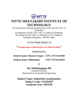
  • 11. Case study on Aerodynamics of HAWTs Department of Aeronautical Engineering, NMIT 11 Figure 6: Normal force coefficients measured during dynamic stall on the CER operating in 30° yawed flow and 14 m/s wind. Rotor azimuth positions highlight the differential normal loading from one side of the rotor (90") to the opposite side (270"). The top of the rotor is oriented at 0°. This difference increases yaw loads.[14] when predicting performance. He speculated that dynamic loads could be affected by dynamic stall but did not quantify the potential effects. In 1988 Butterfield ( l989a) was able to quantify both the existence of dynamic stall and its effect on rotor loads by measuring pressure distributions on a 10 m HA WT. Dynamic stall was shown to occur under a variety of inflow conditions, including turbulence, tower shadow, and yawed flow. Figure 6 shows typical rotating blade dynamic stall measurements during yawed operation, compared to static, wind-tunnel test data. The blade azimuth positions are marked on the hysteresis curve to illustrate the difference between normal forces on opposite sides of the rotor (90° and 270°). As mentioned earlier, the existence of hysteresis and its phasing relative to azimuth position significantly increases yaw loads. Figure 8 shows the tangential force coefficients for the same test conditions. Dynamic stall formation can be detected through close examination of pressure distribution time sequences. Suction surface pressures are plotted for one rotor revolution for 30° yawed operation. The vortex development is implied by the leading-edge suction peak rise. At 1800 azimuth position the suction peak drops and pressure maxima can be seen moving towards the trailing edge as the blade progresses in time.
  • 12. Case study on Aerodynamics of HAWTs Department of Aeronautical Engineering, NMIT 12 3.2.2 Dynamic Inflow Dynamic inflow refers to lagging in the response of the induced velocity field of a rotor following rapid changes in the rotor operating state. The mass of the air in the wake of the rotor makes it impossible for the wake to respond instantaneously to a change in rotor loading such as might be observed after a change in blade pitch angle. Two general approaches are being taken to analyse dynamic inflow. The first is suitable for use with the BEM method and the second is more computationally intensive. In the simpler approach, a linear, first-order model is assumed for the induced velocity. A time constant for the induction lag is determined in a variety of ways. Bierbooms ( 1990a) uses a time constant which is twice the time scale for the rotor disk, 2D/ V. Other time constant methods are described by Snel & Schepers ( 1991 ) . The dynamic inflow theory of Pitt & Peters provides one method for determining the time constants and has the additional advantage of incorporating skewed wake effects (Gaonkar & Peters 1986, Pitt & Peters 1981 ) . This is the same method described earlier for quasi-steady analysis of yawed rotors. The time constants in this method asymptotically approach actuator disk values for flow normal to the rotor (zero yaw) and results from detailed vortex trajectory calculations for flow parallel to the rotor plane. The second approach to analysing dynamic inflow uses a vortex wake calculation. This method is inherently more satisfying since it enables one to directly calculate the motion of the vortex trajectories without needing to make assumptions regarding the time constant of the flow. In principle these methods can also treat dynamic stall directly, since the location and motion of all shed and trailing vorticity is determined at every time step. However, other assumptions, such as convection velocities and/or wake shape, are required to make the analysis tractable with current computers. At this time there is not sufficient data to determine whether the more complex methods are more accurate. 3.3 Transitory Yaw effects The mechanical systems used for yaw control cannot track the wind to give perfect alignment at all times, so some yaw misalignment angle must always be expected. Combined with the low tip speeds of HAWTs, this can produce large excursions in relative flow velocity, which can amplify unsteady effects even although the blade pitch and angle of attack may remain relatively low and/or constant. Amplitude and phase
  • 13. Case study on Aerodynamics of HAWTs Department of Aeronautical Engineering, NMIT 13 Figure 7: Representative predictions of transient power output for a change in yaw misalignment angle relative to the wind direction[19] changes of the local forces are then produced on the blades compared to those loads that might be obtained if only quasi-steady aerodynamics had been assumed, and this can be a significant source of predictive deficiency. Another source of unsteady effects can be traced to the actual direction of the incident flow velocities at each element on the rotating blades as they are approaching stall. Because of the relatively low rotational velocity of HAWTs, the local sweep angle of the flow with respect to the leading edge of the blade can become relatively large when the turbine is yawed by even a few degrees. With fully attached flows the independence principle of aerodynamic loads applies, and insignificant changes in air loads will be expected. However, as already discussed the radial flow component can affect the development of the 3-dimensional boundary layer on the blade, and so also alter the conditions that eventually may lead to the onset of dynamic stall. This is just one more reason why the prediction of stall on HAWTs is so difficult to represent by using parsimonious mathematical models.
  • 14. Case study on Aerodynamics of HAWTs Department of Aeronautical Engineering, NMIT 14 3.4 Rotor Design 3.4.1 Number of Blades Horizontal-Axis Wind Turbines may be designed with one, two, three, or more blades. The fewer blades a wind turbine has, the faster the blades must turn to harvest the same amount of energy as a wind turbine with more blades. Smaller, residential-size units are designed for cost efficiency and the size of the electrical load of the home. Turbines used for commercial production of electric power may be two-blade, three-blade or five-blade, all of which are designed for much larger energy loads. 3.4.1.1 Single-Blade Turbines Single-blade wind turbines are used in a few limited applications, but they are the least used of all the Horizontal-Axis Wind Turbines. To rotate smoothly, single-blade turbines must have one or two counterbalances. The advantage of this type of wind turbine is the lower cost because of the use of only one turbine blade (and the small weight savings), but single-blade turbines must run at much higher speeds to convert the same amount of energy from the wind as two-blade or three-blade turbines with the same size blades. Because the single-blade turbine must run at higher speeds, more wear and fatigue are generated on the blade and bearings in the mounting mechanism, which in turn means higher maintenance costs over the life of the turbine. Single-blade turbines also require extensive setup procedures to ensure that the blade is mounted perfectly and is balanced to limit oscillation and vibration. Because of these problems, very few single-blade turbines are in use today.
  • 15. Case study on Aerodynamics of HAWTs Department of Aeronautical Engineering, NMIT 15 Figure 8: Single-Blade Horizontal-Axis Wind Turbine with Two Counterbalances.[18] 3.4.1.2 Two-Blade Wind Turbines Compared to three-blade turbines, two-blade wind turbines have the advantage of saving on the cost and the weight of the third rotor blade, but they have the disadvantage of requiring higher rotational speed to yield the same energy output. This is a disadvantage in terms of both noise and wear of critical bearings, shafts, and gearboxes. Two-blade turbines have experienced high-fatigue failures of the blade and other mechanical parts, so they have limited application. Figure 7 shows a two-blade wind turbine. Another way to improve the efficiency of the two-blade turbine is to make the two blades thicker and wider than traditional turbine blades so that the two blades can convert more wind energy. The thicker blades also mean that the blades are stronger and better able to resist fatigue problems.
  • 16. Case study on Aerodynamics of HAWTs Department of Aeronautical Engineering, NMIT 16 Figure 9: Typical Two-Blade Wind Turbine.[18] New composite materials allow the increased size without adding substantial weight to each blade. These materials also allow the blade to be produced at a lower cost. Even with these more efficient blades, however, the two-blade turbine is still slightly less efficient than the three-blade turbine. One advantage to a two-blade turbine is that it is faster and safer to install than the three- blade version. The two-blade turbine can be lifted into position after the turbine blades have been mounted while it is still on the ground because the blades can be mounted in a horizontal position and easily lifted as a unit. A three-blade turbine always has one blade pointing downward if it is raised as a unit, so it is more difficult to get the larger wind turbines off the ground as a unit for mounting. 3.4.1.3 Three-Blade Wind Turbines The majority of large horizontal-axis wind turbines use three blades, with the rotor position maintained upwind by the yaw control. Figure 8 shows a three-blade wind turbine. The three blades provide the most energy conversion while limiting noise and
  • 17. Case study on Aerodynamics of HAWTs Department of Aeronautical Engineering, NMIT 17 vibration. The three blades provide more blade surface for converting wind energy into electrical energy than a two-blade or single-blade wind turbine. The blades for the larger horizontal-axis wind turbines are so large they must be transported individually by a truck and trailer. This also means that one or more very large cranes are needed to set the tower and turbine in place. The tower to hold the larger three-blade turbine must also be larger and reinforced to support the weight and to withstand the increased wind power that is harvested to produce its maximum output. The blades on larger three-blade wind turbines are typically installed one at a time after the nacelle is mounted on the tower. On smaller three-blade turbines, the blades can be mounted to the rotor while the rotor is on the ground. Then the entire rotor assembly is lifted with a crane and attached to the shaft after the nacelle is mounted on the tower. Figure 10: Three-Blade Wind Turbine.[18] 3.4.1.4 Five-Blade Wind Turbines A few wind turbines have five blades to produce electrical energy efficiently from low-speed winds. A five-blade wind generator normally has narrower and thinner
  • 18. Case study on Aerodynamics of HAWTs Department of Aeronautical Engineering, NMIT 18 blades, which creates issues with strength. While they are excellent in low-speed winds, they become inefficient in high-speed winds and they are noisier. The tower and base are mounted into the roof of the building, which is a concrete- reinforced building. This type of five-blade wind turbine needs a very strong base and tower to hold the wind turbine in the wind. The thickness of the tower and the cowling around the blades helps direct wind directly into the blades. Figure 11: Five-Blade Wind Turbine.[18] 3.5 Computational Fluid Dynamics Computational fluid dynamics (CFD), based on Euler or Navier-Stocks equations, has potential to provide a consistent and physically realistic simulation of the turbine flow field, and can naturally be used to solve the complex flow over the wind turbine. According to the capabilities that the length scales of turbulence are modelled, CFD can basically be divided into three catalogues for the simulations of wind turbine flow field: Reynolds averaged Navier-Stokes (RANS), LES, and direct numerical simulation (DNS). RANS approach with empirical turbulence model has been widely applied to almost all range of flow problems experienced by wind turbines. Figure 6 shows a typical rotor wake structure calculated using RANS code. Two equations k-omega SST turbulence model developed by Menter71 is considered to be the most outstanding representative
  • 19. Case study on Aerodynamics of HAWTs Department of Aeronautical Engineering, NMIT 19 Figure 12: CFD simulation for rotor wake generated during operation[13] among numerous existing turbulence models for wind turbine applications. But the results from the present investigations suggest that the empirical parameters in the turbulence model can markedly affect the simulation results. An alternative with better accuracy is LES which has been a growing interest in the area of rotor flow field simulations. The main idea of LES is that large eddies are directly resolved and the effect of the small eddies is modelled by sub grid scale model. A sub grid-scale stress model is indispensable for the closure of LES equations. Therefore, a variety of sub grid-scale stress models have been proposed, LES has more attraction to rotor wake analysts, but is still prohibited to deal with the near surface regions due to its huge computational overhead. Therefore, a combined approach, detached eddy simulation (DES), in which RANS and LES are adopted in the near-surface and far-surface, respectively, has been proved to obtain good solution. DNS, which directly solves full Navier-Stokes equations and needs to catch all relevant scales of turbulence with ultrafine computational grid, is currently impossible to be applied in full wind turbine flow field. CFD methods are making inroads into the fields of industrial applications associated with both design and analysis.82 However, either of the RANS or LES, at least so far, has been applied only to very specific cases due to the massive computational costs and numerical issues.
  • 20. Case study on Aerodynamics of HAWTs Department of Aeronautical Engineering, NMIT 20 3.6 Experimental Aerodynamic Studies for HAWTs As in other aerodynamic areas experimental study is indispensable to wind turbine aerodynamics. Numerous experiments on wind turbines have been performed over the last three decades. The experimental study is usually carried out by two means i.e., operation in field and tests in wind tunnels. Field experiments have been largely carried out over many years which have been well documented through IEA Wind Annex XIV83 and Annex XVIII.84 These files contain a large number of measurement data associated to many types of different machines. Field experiments can provide comprehensive aerodynamic and dynamic information for wind turbines operating in natural conditions. However, such experiments are typically very time consuming expensive and complicated through the large volumes of data and the extensive data reduction which are required. It is therefore often common to utilize wind tunnel testing which can be executed under controlled test conditions. A well-known experiment is the NREL unsteady aerodynamics experiment (UAE) Phase VI turbine test in the NASA Ames 24.4 m × 36.6 m wind tunnel accomplished in 2000. The test model was a two-bladed stall- regulated wind turbine with a diameter of 10.1 meters. More detailed information about the experiment has been documented by Hand.29 Another systemic wind turbine test in wind tunnel is the so-called model experiment in controlled conditions (MEXICO) subjected to the European 5th Framework Programme.85 The MEXICO turbine had a three bladed pitch-controlled upwind rotor that was 4.5 m in diameter and was tested in the NFAC 9.5 m × 9.5 m wind tunnel.
  • 21. Case study on Aerodynamics of HAWTs Department of Aeronautical Engineering, NMIT 21 4. Conclusion BEM theory, regardless of its simplification, is still a daily design tool for wind turbines. However, BEM method has many natural shortcomings, and relatively less ability to model the physics of the turbine aerodynamics in the field of high unsteady conditions, such as atmospheric turbulence, wind shear, deep stall, interactions of neighboring turbines, wake and etc. Therefore, more sophisticated vortex wake models have been developed to directly deal with vortices that dominate the wind turbine flow field in essence and therefore may provide relatively reliable information although they require more validations. Introduction of dynamic stall model and 3D rotational effect model greatly improves the wind turbine aerodynamic load calculations. However, more accurate dynamic stall models and delay stall models are required, which can be developed only through much more experimental and computational studies. CFD methods have provided deep insight to wind turbine flow fields. However, CFD methods have not been used for design purposes with confidence. Nevertheless, with the increase in computer power and with the advances in computational techniques the CFD solver is becoming a promising and powerful tool for analysis of wind turbine aerodynamics. Wind turbine experiments are essential not only for understanding of the aerodynamic mechanism but also for code validation. By consideration of the complexity of wind turbine operation conditions, the investigation of turbine aerodynamic is still particularly challenging for wind energy exploitation.
  • 22. Case study on Aerodynamics of HAWTs Department of Aeronautical Engineering, NMIT 22 5. Bibliography [1].H. Glauert, in: W. F. Durand ed. Aerodynamic Theory (Springer, Berlin, 1935). [2].R. Mikkelsen, J. N. Sørensen, and W. Z. Shen, Wind Energ. 4, 121 (2001). [3].M L. Buhl Jr. A New Empirical Relationship between Thrust Coefficient and Induction Factor for the Turbulent Windmill State (Boulevard, Golden, Colorado, USA, 2005). [4].M. O. L. Hansen, Aerodynamics of Wind Turbines (Earthscan Publications Ltd., 2008). [5]. J. R. P. Vaza, J. T. Pinhob, and A. L. A. Mesquitaa, Renew Energy 36, 1734 (2011). [6]. T. G. Wang, L. Wang, and W. Zhong, et al., Chin. Sci. Bull. 57, 466 (2012). [7]. L. Wang, T. G. Wang, and Y. Luo, Appl. Math. Mech. Eng.Ed. 32, 739 (2011). [8]. L. Wang, T. G. Wang, and J. H. Wu, et al., J. NUAA 43, 672 (2011). (in Chinese) [9]. M. A. Kotb, and M. M. Abdel Haq, Wind Eng. 16, 95 (1992). [10]. F. N. Coton, T. G. Wang, and R. A. M Galbraith, Wind Energy 5, 199 (2002). [11]. F. N. Coton, and T. G. Wang, Journal of Power and Energy 213, 33 (1999). [12]. T. G. Wang, and F. N. Coton, J. Wind Een. Ind. Aerod. 89, 873 (2001). [13]. “A brief review on wind turbine aerodynamics” by Tongguang Wanga, Nanjing University of Aeronautics and Astronautics, Nanjing 210016, China (Received 15 July 2012; accepted 25 September 2012; published online 10 November 2012) [14]. AERODYNAMICS OF HORIZONTAL-AXIS WIND TURBINES, by A. C. Hansen, Mechanical Engineering Department, University of Utah and C. P. Butterfield, National Renewable Energy Laboratory, Golden, Colorado [15]. Wind Energy Handbook, Second Edition. Tony Burton, Nick Jenkins, David Sharpe and Ervin Bossanyi. © 2011 John Wiley & Sons, Ltd. Published 2011 by John Wiley & Sons, Ltd. ISBN: 978-0-470-69975-1
  • 23. Case study on Aerodynamics of HAWTs Department of Aeronautical Engineering, NMIT 23 [16]. “Designing a Horizontal-Axis Wind Turbine for South Khorasan Province: A Case Study” by Mehdi Jahangir, Department of Mechanical Engineering, Faculty of Technical Engineering, Shahrekord Branch, Islamic Azad University, Shahrekord, 88137-33395, Iran and Akbar Alidadi Shamsabadi, Young Researchers and Elite Club, Shahrekord Branch, Islamic Azad University, Shahrekord, Iran. [17]. Horizontal Axis Wind Turbine Blade Design Methodologies for Efficiency Enhancement—A Review by Shafiqur Rehman1 , Md. Mahbub Alam 2 , Luai M. Alhems 1 and M. Mujahid Rafique 3 1. Center for Engineering Research, King Fahd University of Petroleum and Minerals,Dhahran-31261, Saudi Arabia; srehman@kfupm.edu.sa (S.R.); luaimalh@kfupm.edu.sa (L.M.A.) 2. Institute for Turbulence-Noise-Vibration Interaction and Control, Shenzhen Graduate School, Harbin Institute of Technology, Shenzhen 518055, China 3. Mechanical Engineering Department, King Fahd University of Petroleum and Minerals, Dhahran-31261, Saudi Arabia; mujahidrafique89@gmail.com [18]. https://electricalacademia.com/renewable-energy/horizontal-axis-wind-turbine-hawt- working-principle-single-blade-two-blade-three-blade-wind-turbine/ [19]. Leishman, J.G.: Wind Energy 5, 86–132 (2002)