Downloaded 72 times
![A
Seminar Report
on
Wind Turbine Lightning
Protection
Submitted By:
Borase Devendra Vijayrao
B.E. [Department of Mechanical Engineering]
Guided By:
Prof.V.M.Patil
Department of Mechanical Engineering
R. C. Patel Institute of Technology,
Shirpur-425405
2016-17](https://image.slidesharecdn.com/e0d6f8d3-48db-4757-ae03-4aac509e597a-161027080920/85/DEva-Report-1-320.jpg)
![A
Seminar Report
on
Wind Turbine Lightning
Protection
Submitted By:
Borase Devendra Vijayrao
B.E. [Department of Mechanical Engineering]
Guided By:
Prof.V.M.Patil
Department of Mechanical Engineering
R. C. Patel Institute of Technology,
Shirpur-425405
2016-17](https://image.slidesharecdn.com/e0d6f8d3-48db-4757-ae03-4aac509e597a-161027080920/75/DEva-Report-1-2048.jpg)
![Shirpur Education Society’s
R. C. Patel Institute of Technology,
Shirpur, Dist-Dhule
CERTIFICATE
This is to certify that Borase devendra Vijayrao
from B.E[Mechanical Engineering] has satisfactorily car-
ried out seminar work on “Wind Turbine Lightning
Protection” and submitted the report in the premises of
Department of Mechanical Engineering under the guid-
ance of Prof.V.M.Patil during year 2016-2017.
Date:
Place: Shirpur
Seminar Guide Coordinator
Head of Department Principal](https://image.slidesharecdn.com/e0d6f8d3-48db-4757-ae03-4aac509e597a-161027080920/85/DEva-Report-2-320.jpg)
![Acknowledgement
I take this opportunity to express my heartfelt gratitude towards the Depart-
ment of Mechanical Engineering, RCPIT, Shirpur that gave me an opportunity for
presentation of my seminar in their esteemed organization.
It is a privilege for me to have been associated with Prof.V.M.Patil, my guide
during seminar work. I have been greatly benefited by her valuable suggestion and
ideas. It is with great pleasure that I express my deep sense of gratitude to her for
her valuable guidance, constant encouragement and patience throughout this work.
I express my gratitude to Prof.N.P.Salunke[Head Of Department] for his con-
stant encouragement, co-operation and support and also thankful to all people who
have contributed in their own way in making this seminar success.
I take this opportunity to thank all the classmates for their company during the
course work and for useful discussion I had with them.
Under these responsible and talented personalities I was efficiently able to com-
plete my seminar in time with success.
Borase Devendra Vijayrao](https://image.slidesharecdn.com/e0d6f8d3-48db-4757-ae03-4aac509e597a-161027080920/85/DEva-Report-3-320.jpg)

![Chapter 2
Literature Survey
McElroy et al.[1], Mongolia, sandwiched between Russia and China, has
a high potential for wind-powered energy. As an emerging and developing country
with a large land size, Mongolia is an excellent choice for renewable energy practices,
according to McElroy at al. (2009). Currently, coal is used as the major source of
energy in the area because it is abundant and cheap. However, with the advancement
of wind turbine technology and its widespread use and production, wind powered
energy is becoming a cost effective way to harness energy sustainably . A sustainable
energy resource is one that can be used renewably over our lifetimes and brings little
to no impact on our worlds ecosystems.
Khushrushahi et al [2], Currently, according to Noushin Khushrushahi
et at. (2006), Mongolia receives the majority of energy from coal-powered plants.
Coal is a readily available fuel because nearly half of Mongolia is a coal basin. This
makes coal very easy to obtain and very cheap for energy generation. Because
Mongolia uses so little energy (compared to developed nations), most people see
little sense in changing to a more expensive and harder to install renewable energy.
Up to eighty percent of Mongolias energy is from coal and the remaining comes
mostly from hydroelectric generators. To date, Mongolia uses just under 800 MW
of energy but is steadily increasing their need for energy. In theory, the cheapest
and easiest way for Mongolia to obtain more power would be to import their energy
from China.
6](https://image.slidesharecdn.com/e0d6f8d3-48db-4757-ae03-4aac509e597a-161027080920/85/DEva-Report-13-320.jpg)
![RCPIT, Shirpur Department of Mechanical Enggineering
Zervos et.al [3], the Asian market added nearly one third of the total
new wind generators installed worldwide in 2008. In total, 36.5 billion (50 billion)
was spent on turbine instillations worldwide that year. Almost half a million people
are employed in some way by the wind energy industry and that number is growing
steadily. With the current use of wind energy, over 158 million tons of carbon
dioxide are saved from entering the atmosphere annually. Today, the United States
leads with the world in wind energy generation, producing over 25,000 MW . Wind
energy is now being produced world-wide and developing nations have began turning
to wind powered renewable energy.
Wind Turbine Lightning Protection 7](https://image.slidesharecdn.com/e0d6f8d3-48db-4757-ae03-4aac509e597a-161027080920/85/DEva-Report-14-320.jpg)
![RCPIT, Shirpur Department of Mechanical Enggineering
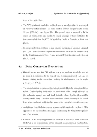
4.5 Grounding
The grounding details are described for a typical turbine in Figure 13 and Figure
14. The grounding electrode was significantly modified with a retrofit designed by
Rich Kithill at the National Lightning Safety Institute (NLSI). Some observations
of the details follow:
• Each of the four tower legs are tied to a ground wire inside the concrete pier
(Ufer ground).
• Each tower leg is connected by copper braid to a ring electrode [30.5 m (100
ft) of 2/0].
• Two of the tower legs are connected by 2/0 copper braid to 46 m (150 ft) of
38 mm (1.5 in.) copper strap buried in irrigated bentonite laid out in 0.9 x 15
m (3 x 50 ft) radial crow’s feet (irrigated twice a month).
• All 3 phases of the 25 kV buried site feeder has a common braid terminated
at each turbine transformer box (primary side).
• The air terminal (lightning rod) on the nacelle has insulated 4/0 Cu welding
cable conducting to the ground braid (no bond to tower).
• The generator J-Box (generator ground) is connected by insulated 4/0 Cu
conductor to a tower bond 1.5 m (5 ft) from base (below sensor) and control
box.
• The controller path to ground is either via the neutral cable or via the feeder
transformer box into a ground rod and the ring electrode.
• The controller and uptower generator surge protection device clamps to SP
ground.
Wind Turbine Lightning Protection 15](https://image.slidesharecdn.com/e0d6f8d3-48db-4757-ae03-4aac509e597a-161027080920/85/DEva-Report-22-320.jpg)
![References
[1] I.Cotton, B. McNiff, T. Soerenson, W. Zischank, P. Christiansen,
M.Hoppe-Kippler, S. Ramakers, P. Pettersson and E. Muljadi: ”Light-
ning Protection for Wind Turbines”, Proceedings of the 25th International
Conference on Lightning Protection (ICLP), (Rhodes,Greece), pp.848-853,
2000 .Wada et al.: ”Lightning Damages of Wind Turbine Blades in Win-
ter in Japan -Lightning Observation on the Nikaho-Kogen Wind Farm-”,
Proceedings of the 27th International Conference on Lightning Protec-
tion(ICLP), (Avignon,France), pp.947-952, 2004
[2] EC TR 61400-24, Wind turbine generator systems-Part 24:Lightning pro-
tection, 2002
[3] .Yokoyama, N.J.Vasa: ”Manner of Lightning Attachment to Non-
conductive Wind Turbine Blades”, Proceedings of the 27th International
Conference on Lightning Protection (ICLP), (Avignon,France), pp.936-
940, 2004
[4] akehiro Naka, Nilesh J. Vasa, Shigeru Yokoyama, Atsushi Wada, Akira
Asakawa, Hideki Honda, Kazuhisa Tsutsumi and Shinji Arinaga: ”Study
on Lightning Protection Methods for Wind Turbine Blades”, IEEJ Trans-
actions on Power and Energy, Vol.125, No.10, pp.993-999, 2005
20](https://image.slidesharecdn.com/e0d6f8d3-48db-4757-ae03-4aac509e597a-161027080920/85/DEva-Report-27-320.jpg)
![References
[1] I.Cotton, B. McNiff, T. Soerenson, W. Zischank, P. Christiansen,
M.Hoppe-Kippler, S. Ramakers, P. Pettersson and E. Muljadi: ”Light-
ning Protection for Wind Turbines”, Proceedings of the 25th International
Conference on Lightning Protection (ICLP), (Rhodes,Greece), pp.848-853,
2000 .Wada et al.: ”Lightning Damages of Wind Turbine Blades in Win-
ter in Japan -Lightning Observation on the Nikaho-Kogen Wind Farm-”,
Proceedings of the 27th International Conference on Lightning Protec-
tion(ICLP), (Avignon,France), pp.947-952, 2004
[2] EC TR 61400-24, Wind turbine generator systems-Part 24:Lightning pro-
tection, 2002
[3] .Yokoyama, N.J.Vasa: ”Manner of Lightning Attachment to Non-
conductive Wind Turbine Blades”, Proceedings of the 27th International
Conference on Lightning Protection (ICLP), (Avignon,France), pp.936-
940, 2004
[4] akehiro Naka, Nilesh J. Vasa, Shigeru Yokoyama, Atsushi Wada, Akira
Asakawa, Hideki Honda, Kazuhisa Tsutsumi and Shinji Arinaga: ”Study
on Lightning Protection Methods for Wind Turbine Blades”, IEEJ Trans-
actions on Power and Energy, Vol.125, No.10, pp.993-999, 2005
21](https://image.slidesharecdn.com/e0d6f8d3-48db-4757-ae03-4aac509e597a-161027080920/85/DEva-Report-28-320.jpg)

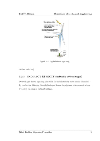
This seminar report summarizes lightning protection systems for wind turbines. It discusses the types of wind turbines, including horizontal axis and vertical axis turbines. It also describes the effects of lightning and how it can damage structures. The report outlines critical elements for blade lightning protection systems, including low-impedance conductors and permanent connections. It also discusses receptor attachment and existing lightning protection standards. The report provides an overview of wind turbine protection components and grounding practices.