Download to read offline
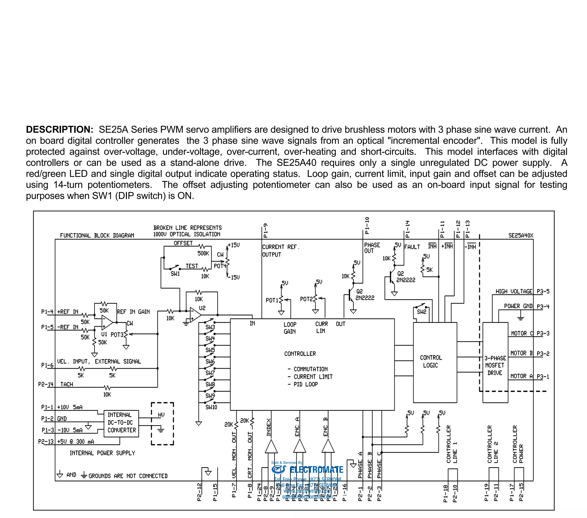
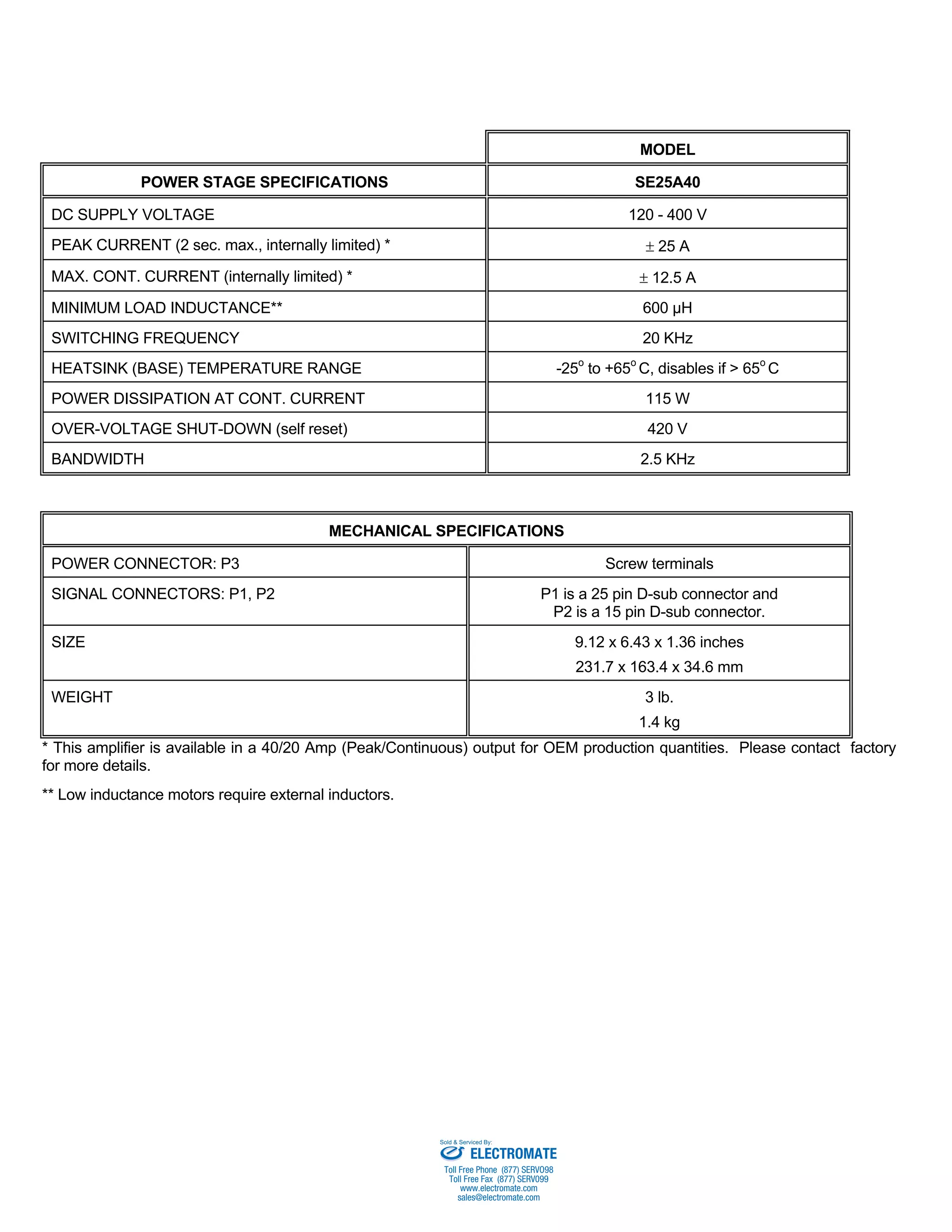
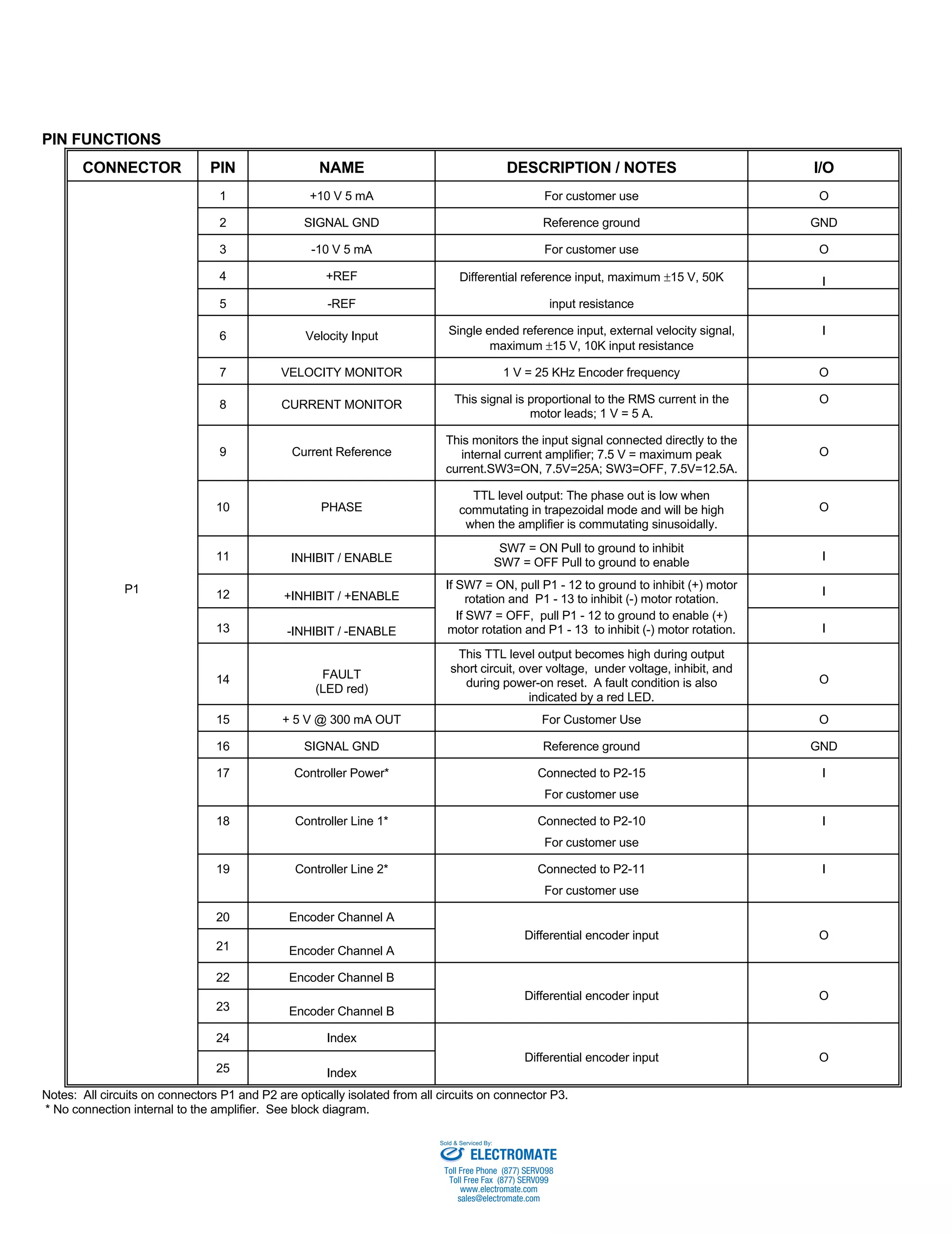
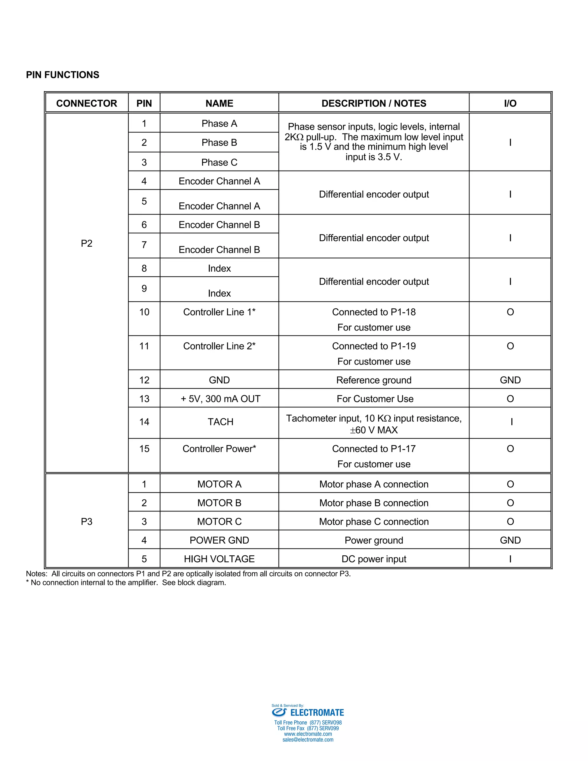
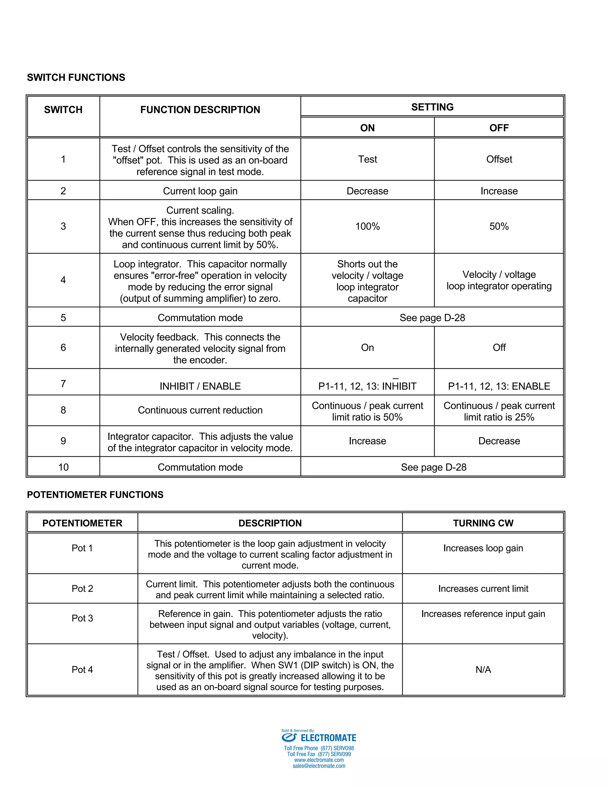
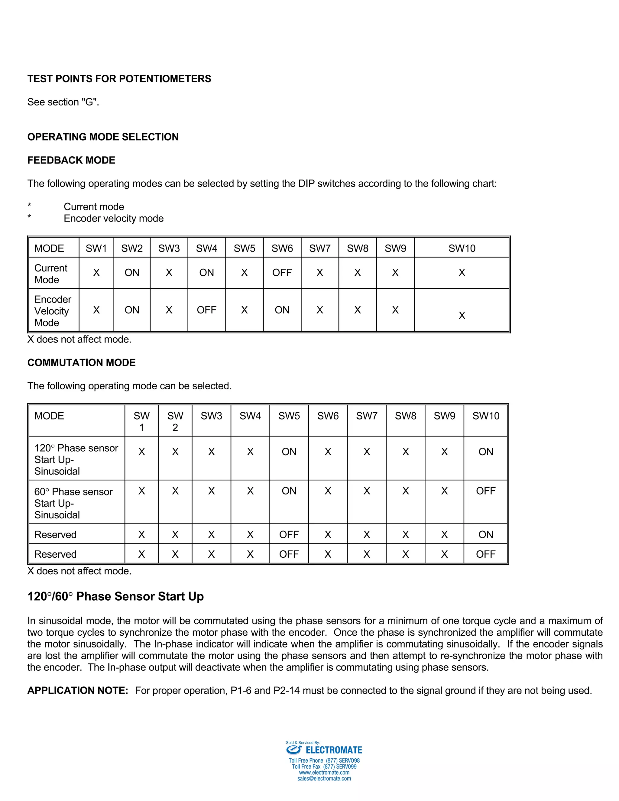

The document describes the SE25A40 brushless servo amplifier. It is a small, surface-mount amplifier that can operate in current or encoder velocity mode. It provides sinusoidal commutation for 3-phase brushless motors from 120-400V DC power. It has protection against overheating, overcurrent, and other faults.


![Vibe Coding vs. Spec-Driven Development [Free Meetup]](https://cdn.slidesharecdn.com/ss_thumbnails/vibecodingvsspecdrivendevelopment-251209105622-43f455e7-thumbnail.jpg?width=640&height=640&fit=bounds)


