Download to read offline


![1.3 Multivector and SIMD Computers 29
' Scalar "FrocVs^oi
Scalar
Functional
Pipelines
Scalar nstmctions;
Vector Processor
Scalar
Control Unit
Vector ^
Instruclions
Instructions
Scalar
Data
Vector
Control Unit
Main Memory Vector
(Program and Data)! D a t a :
1
HOSt
mpuler]
T
Control
I
Vector Func. Pipe.
Vector Func. Pipe.
I/O (User)
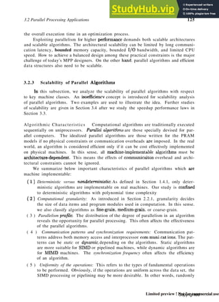
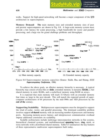
Figure 1.11 The architecture of a vector supercomputer.
Vector Processor Models Figure l.ll shows a rt:gister-to-register architecture.
Vector registers are used to hold the vector operands, intermediate and final vector
results. The vector functional pipelines retrieve operands from and put results into the
vector registers. AH vector registers are programmable in user instructions. Each vector
register is equipped with a component counter which keeps track of the component
registers used in successive pipeline cycles.
The length of each vector register is usually fixed, say, sixty-four 64-bit component
registers in a vector register in a Cray Series supercomputer. Other machines, like the
Fujitsu VP2000 Series, use reconfigurable vector registers to dynamically match the
register length with that of the vector operands.
In general, there are fixed numbers of vector registers and functional pipelines in
a vector processor. Therefore, both resources must be reserved in advance to avoid
resource conflicts between different vector operations. Several vector-register based
supercomputers are summarized in Table 1.5.
A memory-to-memory architecture differs from a register-to-register architecture
in the use of a vector stream unit to replace the vector registers. Vector operands and
results are directly retrieved from the main memory in superwords, say, 512 bits as in
the Cyber 205.
Pipelined vector supercomputers started with uniprocessor models such as the Cray
1 in 1976. Recent supercomputer systems offer both uniprocessor and multiprocessor
models such as the Cray Y-MP Series. Most high-end mainframes offer multiprocessor
Copyrighted material
Limited preview ! Not for commercial use](https://image.slidesharecdn.com/advancedcomputerarchitectureparallelismscalabilityprogrammabilitybaasiitecitft-230804180027-da4f37dd/85/ADVANCED-COMPUTER-ARCHITECTURE-PARALLELISM-SCALABILITY-PROGRAMMABILITY-Baas-IiteCitft-48-320.jpg)


![L4 PRAM and VLSI Models 35
NP: NondeEennirmric polynomial-
time class
P: Polynomial*time class,
NPC: NP-complete class
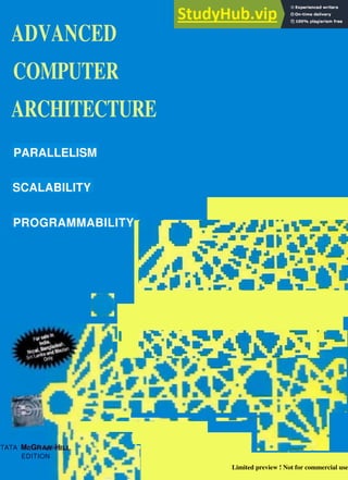
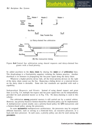
Figure 1.13 The relationships conjectured among the NP, P, and N P C clashes of
computational problems.
P R A M Models Conventional uniprocessor computers have been modeled as random-
access machines (RAM) by Sheperdson and Sturgis (1963), A parallel random-access
machine (PRAM) model has been developed by Fortune and Wyllie (1978) for model-
ing idealized parallel computers with zero synchronization or memory access overhead.
This PRAM model will be used for parallel algorithm development and for scalability
and complexity analysis.
Tightly
synchronized"
C^D—
Figure 1.14 PRAM model of a multiprocessor system with shared memory, on
which all n processors operate in lockstep in memory access and pro-
gram execution operations. Each processor can access any memory
location in unit time.
An n-processor PRAM (Fig. 1.14) has a globally addressable memory. The shared
memory can be distributed among the processors or centralized in one place. The n
processors [also called processing elements (PEs) by other authors] operate on a syn-
chronized read-memory, compute, and write-memory cycle. With shared memory, the
model must specify how concurrent read and concurrent write of memory are handled.
Four memory-update options are possible:
Exclusive read (ER) — This allows at mast one processor to read from any
memory location in each cycle, a rather restrictive policy.
Copyrighted material
Limited preview ! Not for commercial use](https://image.slidesharecdn.com/advancedcomputerarchitectureparallelismscalabilityprogrammabilitybaasiitecitft-230804180027-da4f37dd/85/ADVANCED-COMPUTER-ARCHITECTURE-PARALLELISM-SCALABILITY-PROGRAMMABILITY-Baas-IiteCitft-54-320.jpg)


![46 Parallel Computer Models
tutorial [Lilja92]. [Almasi89] and Gottlieb provided a thorough survey of research done
on parallel computing up to 1989. [Hwang89a] and DeGroot presented critical reviews on
parallel processing techniques developed for supercomputers and artificial intelligence.
[Hennessy90] and Patterson provided an excellent treatment of uniprocessor com-
puter design. For a treatment of earlier parallel processing computers, readers are
referred to [Hwang84] and Briggs. The layered classification of parallel computers was
proposed in [Ni91j. [Bell92] introduced the MIMD taxonomy. Systolic array was intro-
duced by [Kung78] and Leiserson. [Prasanna Kumar87] and Raghavendra proposed the
mesh architecture with broadcast buses for parallel computing.
Multiprocessor issues were characterized by [Gajski85] and Pier and by [Dubois88],
Scheurich, and Briggs. Multicomputer technology was assessed by [Athas88] and Seitz.
An introduction to existing parallel computers can be found in [TVewOl] and Wilson.
Key references of various computer systems, listed in Bell's taxonomy (Fig. 1.10) and
in different architectural development tracks (Figs. 1.17 through 1.19), are identified
in the figures as well as in the bibliography. Additional references to these case-study
machines can be found in later chapters. A collection of reviews, a bibliography, and
indexes of resources in parallel systems can be found in [ACM91] with an introduction
by Charles Seitz.
A comparative study of NUMA and COMA multiprocessor models can be found in
(Stenstrom92j, Joe, and Gupta. SIMD machines were modeled by [Siegel79]. The RAM
model was proposed by [Sheperdson63] and Sturgis. The PRAM model and variations
were studied in [Fortune78] and Wyllie, [Snir82], and [Karp88]. The theory of NP-
completeness is covered in the book by |Cormen90], Leiserson, and Rivest. The VLSI
complexity model was introduced in (Thompson80] and interpreted by [Ullman84] and
by [Seitz90] subsequently.
Readers are referred to the following journals and conference records for information
on recent developments:
• Journal of Parallel and Distributed Computing (Academic Press, since 1983).
• Journal of Parallel Computing (North Holland, Amsterdam, since 1984).
• IEEE Transactions on Parallel and Distributed Systems (IEEE Computer Soci-
ety, since 1990).
• International Conference on Parallel Processing (Pennsylvania State University,
since 1972).
• International Symposium on Computer Architecture (IEEE Computer Society,
since 1972).
• Symposium on the Frontiers of Massively Parallel Computation (IEEE Computer
Society, since 1986).
• International Conference on Supercomputing (ACM, since 1987).
• Symposium on Architectural Support for Programming Languages and Operating
Systems (ACM, since 1975).
• Symposium on Parallel Algorithms and Architectures (ACM, since 1989).
» International Parallel Processing Symposium (IEEE Computer Society, since
1986).
Copyrighted material
Limited preview ! Not for commercial use](https://image.slidesharecdn.com/advancedcomputerarchitectureparallelismscalabilityprogrammabilitybaasiitecitft-230804180027-da4f37dd/85/ADVANCED-COMPUTER-ARCHITECTURE-PARALLELISM-SCALABILITY-PROGRAMMABILITY-Baas-IiteCitft-65-320.jpg)


![130 Principles of Scalable Performance
in a parallel computer, the fixed load is distributed to more processors for parallel
execution. Therefore, the main objective is to produce the results as soon as possible.
In other words, minimal turnaround time is the primary goal. Speedup obtained for
time-critical applications is called fixed-load speedup.
Fixed-Load Speedup The ideal speedup formula given in Eq. 3.7 is based on a
fixed workload, regardless of the machine size. Traditional formulations for speedup,
including Amdahl's law, axe all based on a fixed problem size and thus on a fixed load.
The speedup factor is upper-bounded by a sequential bottleneck in this case.
We consider below both the cases of DOP < n and of DOP > n. We use the
ceiling function x to represent the smallest integer that is greater than or equal to
the positive real number x. When x is a fraction, x] equals 1. Consider the case
where DOP = i > n. Assume all n processors are used to execute W, exclusively. The
execution time of W, is
Thus the response time is
m = g [i] (3.25)
TW = T. £ r (3.26)
-£5fl
Note that if i < n, then U(n) = U(oo) = WifiA. Now, we define the fixed-bod
speedup factor as the ratio of T(l) to T(n):
m
S» = M = "I. ... 0.27)
T{n)
tm
Note that 5 n < 5«, < A, by comparing Eqs. 3.4, 3.7, and 3.27.
A number of factors we have ignored may lower the speedup performance. These
include communication latencies caused by delayed memory access, interprocessor com-
munications over a bus or a network, or operating system overhead and delay caused
by interrupts. Let Q(n) be the lumped sum of all system overheads on an n-processor
system. We can rewrite Eq. 3.27 as follows:
m
5>.
Sn = A = ^T^h, (3-28)
T{n) + Q(n) * jft
rri *
1 = 1
n
+ <3(n)
The overhead delay Q{n) is certainly application-dependent as well as machine-dependent.
It is very difficult to obtain a closed form for Q(n). Unless otherwise specified, we assume
Q(n) = 0 to simplify the discussion.
Copyrighted material
Limited preview ! Not for commercial use](https://image.slidesharecdn.com/advancedcomputerarchitectureparallelismscalabilityprogrammabilitybaasiitecitft-230804180027-da4f37dd/85/ADVANCED-COMPUTER-ARCHITECTURE-PARALLELISM-SCALABILITY-PROGRAMMABILITY-Baas-IiteCitft-149-320.jpg)


![134 Principles of Scalable Performance
can rewrite Eq. 3.31 as follows, assuming Q(n) = 0,
Ew;
where W£ = nW'„ and Vv"i + Wn = W[ -f WJ/tt, corresponding to the fixed-time con-
dition. From Eq. 3.32, the parallel workload W'n has been scaled to n tim?s Wn in a
linear fashion.
The relationship of a scaled workload to Gustafson's scaled speedup is depicted in
Fig. 3.9. In fact, Gustafson's law can be restated as follows in terms of a = W and
1 - a = W„ under the same assumption W] + Wn = 1 that we have made for Amdahl's
In Fig. 3.9a, we demonstrate the workload scaling situation. Figure 3.9b shows the
fixed-time execution style. Figure 3.9c plots S'n as a function of the sequential portion
a of a program running on a system with n = 1024 processors.
Note that the slope of the Sn curve in Fig. 3.9c is much flatter than that in Fig. 3.8c.
This implies that Gustafson's law does support scalable performance as the machine size
increases. The idea is to keep all processors busy by increasing the problem si2e. When
the problem can se;xle to match available computing power, the sequential fraction is no
longer a bottleneck.
3.3.3 Memory-Bounded Speedup Model
Xian-He Sun and Lionel N*i (1993) have developed a memory-bounded speedup
model which generalizes Amdahl's law and Gustafson's law to maximize the use of both
CPU and memory capacities. The idea is to solve the largest possible problem, limited
by memory space. This also demands a scaled workload, providing higher speedup,
higher accuracy, and better resource utilization.
Memory-Bound Problems Large-scale scientific or engineering computations often
require larger memory spare. In fact, many applications of parallel computers are
memory-bound rather than CPU-bound or I/O-bound. This is especially true in a
multicomputer system using distributed memory. The local memory attached to each
node is relatively small. Therefore, each node can handle only a small subproblem.
When a large number of nodes are used collectively to solve a,single large problem,
the total memory capacity increases proportionally. This enables the system to solve a
scaled problem through program partitioning or replication and domain decomposition
of the data set.
/ Instead of keeping the execution time fixed, one may want to use up all the increased
memory by scaling the problem size further. In other words, if you have adequate
Copyrighted material
Limited preview ! Not for commercial use](https://image.slidesharecdn.com/advancedcomputerarchitectureparallelismscalabilityprogrammabilitybaasiitecitft-230804180027-da4f37dd/85/ADVANCED-COMPUTER-ARCHITECTURE-PARALLELISM-SCALABILITY-PROGRAMMABILITY-Baas-IiteCitft-153-320.jpg)


![4.3 Memory Hierarchy Technology 191
CPU
Registers
M,:
(Cache)
(Main Memory)
M3:
(Disk
Storage)
I, Access by word (4 Bytes)
from a cache block of
32Bytes, such as block a.
2. Access by block (32
Bytes) from a memory
page of 32block or 1
KBytes, such as block b
from page B.
Segment G
[a] Segment F
Page A
: Magnetic Tape Unit
(Backup storage)
m
3. Access by page
(1 KBytes) from a
file consisting of
many pages, such as
page A and page B
in segment F
Segment G
4. Segment
transfer with
different num-
ber of pages.
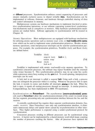
Figure 4.18 The inclusion property and data transfers between adjacent levels of
a memory hierarchy.
The set inclusion relationship implies that all information items are originally stored in
the outermost level Mn- During the processing, subsets of M* are copied into Afn-i*
Similarly, subsets of Mn _i are copied into Ma _2, and so on.
In other words, if an information word is found in M», then copies of the same
word can be also found in all upper levels Mi+i,M»+2,...,Afft. However, a word stored
in Mi+i may not be found in Mv. A word miss in Mf- implies that it is also missing
from all lower levels Arfj-x, Mi_2,..., M. The highest level is the backup storage, where
everything can be found.
Copyrighted material
Limited preview ! Not for commercial use](https://image.slidesharecdn.com/advancedcomputerarchitectureparallelismscalabilityprogrammabilitybaasiitecitft-230804180027-da4f37dd/85/ADVANCED-COMPUTER-ARCHITECTURE-PARALLELISM-SCALABILITY-PROGRAMMABILITY-Baas-IiteCitft-209-320.jpg)


![208 Processors and Memory Hierarchy
Different cache organizations (Section 5.1) may offer different flexibilities in imple-
menting some of the replacement algorithms. The cache memory is often associatively
searched, while the main memory is randomly addressed.
Due to the difference between page allocation in main memory and block alloca-
tion in the cache, the cache hit ratio and memory page hit ratio are affected by the
replacement policies differently. Cache traces are often needed to evaluate the cache
performance. These considerations will be further discussed in Chapter 5.
4.5 B i b l i o g r a p h i c N o t e s a n d E x e r c i s e s
Advanced microprocessors were surveyed in the book by [Tabak9l]. A tutorial on
RISC computers was given by [Stallings90]. Superscalar and superpipelined machines
were characterized by Jouppi and Wall [Jouppi89]. [Johnson91] provided an excellent
book on superscalar processor design. The VLIW architecture was first developed by
(Fisher83].
The Berkeley RISC was reported by Patterson and Sequin in [Patterson82]. A
MIPS R2000 overview can be found in [Kane88]. The HP precision architecture has
been assessed in [Lee89], Optimizing compilers for SPARC appears in [Muchnick88]. A
further description of the M68040 can be found in [Edenfield90].
A good source of information on the i860 can be found in [Margulis90]. The DEC
Alpha architecture is described in [DEC92]. The latest MIPS R4000 was reported
by Mirapuri, Woodacre, and Vasseghi [Mirapuri92]. The IBM RS/6000 was discussed
in [IBM90]. The Hot-Chips Symposium Series [Hotchips91] usually present the latest
developments in high-performance processor chips.
The virtual memory models were based on the tutorial by Dubois and Briggs
[Dubois90c]. The book by [Hennessy90] and Patterson has treated the memory hierar-
chy design based on extensive program trace data. Distributed shared virtual memory
was surveyed in [Nitzberg9l] and Lo.
The concept of a working set was introduced by |Denning68]. A linear program-
ming optimization of the memory hierarchy was reported in [Chow74]. [Crawford90]
explained the paging and segmentation schemes in the i486. Inverted paging was de-
scribed by [Chang88] and Mergen. [Cragon92b] has discussed memory systems for
pipeline processor design.
Exercises
Problem 4.1 Define the following basic terms related to modern processor technology:
(a) Processor design space. (f) Processor versus coprocessor.
(b) Instruction issue latency. (g) General-purpose registers.
(c) Instruction issue rate. (h) Addressing modes.
(d) Simple operation latency. (i) Unified versus split caches.
(e) Resource conflicts. (j) Hardwired versus microcoded control.
Copyrighted material
Limited preview ! Not for commercial use](https://image.slidesharecdn.com/advancedcomputerarchitectureparallelismscalabilityprogrammabilitybaasiitecitft-230804180027-da4f37dd/85/ADVANCED-COMPUTER-ARCHITECTURE-PARALLELISM-SCALABILITY-PROGRAMMABILITY-Baas-IiteCitft-226-320.jpg)


![266 Pipelining and Superscalar Techniques
Asynchronous Model As shown in Fig. 6.1a, data flow between adjacent stages in
an asynchronous pipeline is controlled by a handshaking protocol. When stage S, is
ready to transmit, it sends a ready signal to stage Si+i- After stage 5;+j receives the
incoming data, it returns an acknowledge signal to 5;.
Asynchronous pipelines arc: useful in designing communication channels in message-
passing multicomputers where pipelined wormhole routing is practiced (see Chapter 9).
Asynchronous pipelines may have a variable throughput rate. Different amounts of
delay may be experienced in different stages.
Input
Rooty
Ac*
V Ready,
v
"rar
Sa
AJ
Ready
AW
S*
^ Output
&- Ready
— AC*
(a) An asynchronous pipeline model
Cloc*
LTL
h
JT J]
+ *m A"
(b) A synchronous pipeline model
Time (dock cycles)
2 3 4
St
Slages
S»
S,
X
X
1
X
X
Ss -mgei
L-Uuh
t « Clock period
%m * Maximum stige delay
d M jtch delay
Ack s* Acknowledge si gn&l
Output
(c) Reservation table of a four-stage linear pipeline
Figure 6.1 Two models of linear pipeline units and the corresponding reservation
table.
Synchronous Model Synchronous pipelines are illustrated in Fig. 6.1b. Clocked
latches are used to interface between stages. The latches are made with master-slave
flip-flops, which can isolate inputs from outputs. Upon the arrival of a clock pulse, all
Copyrighted material
Limited preview ! Not for commercial use](https://image.slidesharecdn.com/advancedcomputerarchitectureparallelismscalabilityprogrammabilitybaasiitecitft-230804180027-da4f37dd/85/ADVANCED-COMPUTER-ARCHITECTURE-PARALLELISM-SCALABILITY-PROGRAMMABILITY-Baas-IiteCitft-283-320.jpg)

![268 Pipelining and Superscalar Techniques
In the ideal case 3 = 0, tmox = Tm, and tm m = d. Thus, we have r = *rm + d, consistent
with the definition in Eq. 6.1 without the effect of clock skewing.
6.1.3 Speedup, Efficiency, and Throughput
Ideally, a linear pipeline of k stages can process n tasks in k 4- (n — 1) clock
cycles, where k cycles are needed to complete the execution of the very first task and
the remaining n — 1 tasks require n - 1 cycles. Thus the total time required is
Tk = [k + (n - l)]r (6.4)
where r is the clock period. Consider an equivalent-function nonpipelined processor
which has a flow-through delay of kr. The amount of time it takes to execute n tasks
on this nonpipelined processor is 7 = nkr.
Speedup Factor The speedup factor of a fc-stage pipeline over an equivalent non-
pipelined processor is defined as
__ 7 _ nkr _ nk
k
Tk kr + (n - 1)T k + (n - 1) l
" '
Example 6.1 Pipeline speedup versus stream length
The maximum speedup is 5* —* k as n —* oo. This maximum speedup is very
difficult to achieve because of data dependences between successive tasks (instruc-
tions), program branches, interrupts, and other factors to be studied in subsequent
sections.
Figure 6.2a plots the speedup factor as a function of n, the number of tasks
(operations or instructions) performed by the pipeline. For small values of n, the
speedup can be very poor. The smallest value of £* is 1 when n — 1.
The larger the number A: of subdivided pipeline stages, the higher the potential
speedup performance. When n = 64, an eight-stage pipeline has a speedup value of
7.1 and a four-stage pipeline has a speedup of 3.7. However, the number of pipeline
stages cannot increase indefinitely due to practical constraints on costs, control
complexity, circuit implementation, and packaging limitations. Furthermore, the
stream length n also affects the speedup; the longer the better in using a pipeline.
Optimal Number of Stages The finest level of pipelining is called micropipelining,
with a subdivision of pipeline stages at the logic gate level. In practice, most pipelining
is staged at the functional level with 2 < k < 15. Very few pipelines are designed to
exceed 10 stages in real computers.
On the other hand, the coarse level for pipeline stages can be conducted at the
processor level, called macropipelining. The optimal choice of the number of pipeline
stages should be able to maximize a performance/cost ratio.
Copyrighted material
Limited preview ! Not for commercial use](https://image.slidesharecdn.com/advancedcomputerarchitectureparallelismscalabilityprogrammabilitybaasiitecitft-230804180027-da4f37dd/85/ADVANCED-COMPUTER-ARCHITECTURE-PARALLELISM-SCALABILITY-PROGRAMMABILITY-Baas-IiteCitft-285-320.jpg)

![270 Pipelining and Superscalar Techniques
sponds to an optimal choice for the number of desired pipeline stages:
fco = /-r-r (6.7)
where t is the total flow-through delay of the pipeline. The total stage cost c, the latch
delay <z, and the latch cost h can be adjusted to achieve the optimal value k0.
Efficiency and Throughput The efficiency Eh of a linear fc-stage pipeline is defined
as
* - 'i - ET^i <8
«>
Obviously, the efficiency approaches 1 when n —
» co, and a lower bound on Eh
is X/k when n = 1. The pipeline throughput Hy is defined as the number of tasks
(operations) performed per unit time:
"k =
[k + (n - l)]r =
* + "n-l» ( M )
The maximum throughput f occurs when Eh —* 1 as n —* co. This coincides with
the speedup definition given in Chapter 3. Note that Hh = Eh • / = E^fr = Sh/kr.
6.2 Nonlinear Pipeline Processors
A dynamic pipeline can be reconfigured to perform variable functions at different
times. The traditional linear pipelines are static pipelines because they are used to
perform fixed functions.
A dynamic pipeline allows feedforward and feedback connections in addition to the
streamline connections. For this reason, some authors call such a structure a nonlinear
pipeline.
6.2.1 Reservation and Latency Analysis
In a static pipeline, it is easy to partition a given function into a sequence of
linearly ordered subfunctions. However, function partitioning in a dynamic pipeline
becomes quite involved because the pipeline stages are interconnected with loops in
addition to streamline connections.
A multifunction dynamic pipeline is shown in Fig. 6.3a. This pipeline has three
stages. Besides the streamline connections from S to 52 and from S2 to S3, there is a
feedforward connection from S to 53 and two feedback connections from 53 to 52 and
from 53 to S.
These feedforward and feedback connections make the scheduling of successive
events into the pipeline a nontrivial task. With these connections, the output of the
pipeline is not necessarily from the last stage. In fact, following different dataflow
patterns, one can use the same pipeline to evaluate different functions.
Copyrighted material
Limited preview ! Not for commercial use](https://image.slidesharecdn.com/advancedcomputerarchitectureparallelismscalabilityprogrammabilitybaasiitecitft-230804180027-da4f37dd/85/ADVANCED-COMPUTER-ARCHITECTURE-PARALLELISM-SCALABILITY-PROGRAMMABILITY-Baas-IiteCitft-287-320.jpg)


![420 Multivector and SIMD Computers
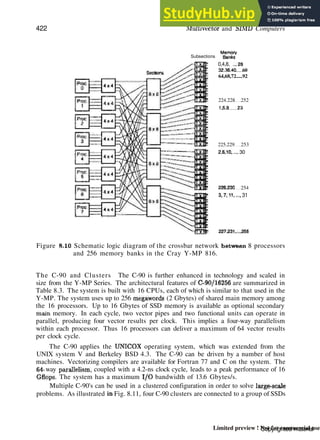
The central memory is divided into 256 interleaved banks. Overlapping memory
access is made possible through memory interleaving via four memory-access ports per
CPU. A 6-ns clock period is used in the CPU design.
nyInterprocesses H -
ommunlcatkxii
j
CPU1
/ Registers -
6 registers *
64 64-bit
elements
per register
T
Registers]
(B 64 btts)
registers
B
Registers
IB 32 bUs)
registers
Instruction
Buffers
(51216-bit
instruction
Parcels
Exchange
Parameter
Registers
S
Registers
(8 64 bits)
registers
A
Registers
(8 32 bits)
registers
Prog ram mabl
Clock (32 bits'
i
I/O Control
Vector
Functional Units
Add/Substract
Shift. Logic.
Population
(64-bit arithmetic)
Floating-point
Functional Units
Add/substract
Multiply
Reciprocal
approximation
(64-bit arithmetic)
Scalar
Functional Units
AdaVSubstract
Shift, Logic.
Population
(32-bit arithmetic)
Address
Functional Unfts
Add/Substract
Multiply
(32-bit arithmetic)
Wector
/Section
J
Scalar
Section
Address
Section
Performance
Monitor
Status
Register
i
J
Control J
Section!
i
i
To External Devices
Figure 8.9 Cray Y-MP 816 system organization. (Courtesy of Cray Research, Inc.,
1991)
The central memory offers 16M-, 32M-, 64M-, and 128M-word options with a max-
imum size of 1 Gbyte. The SSD options are from 32M to 512M words or up to 4
Copyrighted material
Limited preview ! Not for commercial use](https://image.slidesharecdn.com/advancedcomputerarchitectureparallelismscalabilityprogrammabilitybaasiitecitft-230804180027-da4f37dd/85/ADVANCED-COMPUTER-ARCHITECTURE-PARALLELISM-SCALABILITY-PROGRAMMABILITY-Baas-IiteCitft-425-320.jpg)


![9.2 Principles of Multithreading 493
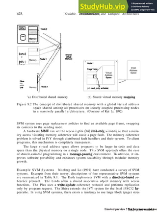
The remote load situation is illustrated in Fig. 9.12a. Variables A and B are
located on nodes N2 and N3, respectively. They need to be brought to node Nl to
compute the difference A - B in variable C. The basic computation demands the
execution of two remote loads (rload) and then the subtraction.
NodeNi
No<MU2
On Node N1, compute: C=A~B demands to execute:
vA = rload pA ,
VB = rload P B ] remote-loads)
C = VA - vB
(a) The remote loads problem
NcoeNi
N0OCN2
On Node Nl, compute: C=A-B
A and B computed concurrently
Thread on Nl must be notified when A. B arc ready
(b) The synchronizing loads problem
Figure 9.12 Two common problems caused by asynchrony and communication la-
tency in massively parallel processors. (Courtesy of R.S. Nikhil. Digital
Equipment Corporation, 1992)
Let pA and pB be the pointers to A and B, respectively. The two rloads can
be issued from the same thread or from two different threads. The context of the
computation on Nl is represented by the variable CTXT. It can be a stack pointer,
a frame pointer, a current-object pointer, a process identifier, etc. In general.
variable names like vA, vB, and C are interpreted relative to CTXT.
In Fig. 9.12b, the idling due to synchronizing loads is illustrated. In this case.
A and B are computed by concurrent processes, and we are not sure exactly when
they will be ready for node Nl to read. The ready signals (readyl and ready2) may
reach node Nl asynchronously. This is a typical situation in the producer-consumer
problem. Busy-waiting may result.
The key issue involved in remote loads is how to avoid idling in node Nl during
the load operations. The latency caused by remote loads is an architectural property.
The latency caused by synchronizing loads also depends on scheduling and the time it
takes to compute A and B, which may be much longer than the transit latency. The
synchronization latency is often unpredictable, while the remote-load latencies are often
predictable.
Copyrighted material
Limited preview ! Not for commercial use](https://image.slidesharecdn.com/advancedcomputerarchitectureparallelismscalabilityprogrammabilitybaasiitecitft-230804180027-da4f37dd/85/ADVANCED-COMPUTER-ARCHITECTURE-PARALLELISM-SCALABILITY-PROGRAMMABILITY-Baas-IiteCitft-476-320.jpg)


![11.6 Bibliographic Notes arid Exercises 661
11.6 B i b l i o g r a p h i c N o t e s a n d Exercises
The material on shared-variable synchronization and access order is based on
[Bitar91] and [Bitar92]. Various synchronization methods were surveyed in [Dinning89].
[Graunke90j and Thakkar have compared synchronization algorithms on shared-memory
multiprocessors.
Binary semaphores were originally proposed by (Dijkstra68). [Hoare74] developed
the use of monitors for operating system structuring. [Wirth77] introduced Module* for
modular multiprogramming. [Perrott79] developed the Actus language for array/vector
processing. [Brinch Hansen75) introduced the Concurrent Pascal language for shared-
variable programming.
For message-passing programming, readers are referred to the Cosmic C Program-
ming Manual by [Seitz89] et al. and the Intel Parallel Programming Primer edited
by [RagsdaleOO]. |Hoare74] developed CSP, which was later modified to Occam by
[Pountain87] and May.
[Gelernter85aj proposed the Linda programming system for asynchronous com-
munications. The material on domain, control, functional, and object decomposition
techniques is based on Intel's iPSC experience. Additional programming examples using
these techniques can be found in the Intel iPSC publication [Ragsdale90j. A parallel
program for solving the N-quecus problem can be found in [Athas88 and Seitz.
Surveys of parallel programming tools were reported in [Chang90 and Smith and in
[Cheng91]. The MIMDizer was introduced in [Harrison90]. A user's guide for MIMDizer
is also directly available from Pacific-Sierra Research Corporation [PSR90]. The Express
is documented in [Parasoft90]. Linda was first introduced by [Gelernter85b] et al. C-
Linda was discussed in [Ahuja86] et al., and SCHEDULE was reported by [Dongarra86]
and Sorensen.
Cray Y-MP software overview can be found in [Cray89]. The Paragon programming
environment is summarized in [Intel91]. The CM-5 software discussion is based on the
technical summary [TMC91J. Additional information on CM-2 software can be found
in [TMC90]. The supercompilers for iPSC/860 are described in |Intel90].
Exercises
Problem 11.1 Explain tin? following terms associated with fast and efficient synchro-
nization schemes on a shared-memory multiprocessor:
(a) Busy-wait versus sleep-wait protocols for sole access of a critical section.
(b) Fairness policies for reviving one of the suspended processes waiting in a queue.
(c) Lock mechanisms for presynchronization to achieve sole access to a critical section.
(d) Optimistic concurrency or the postsynchronization method.
(e) Server synchronization and the corresponding synchronization environment.
Problem 11.2 Distinguish between spin locks and suspend locks for sole access to
Copyrighted material
Limited preview ! Not for commercial use](https://image.slidesharecdn.com/advancedcomputerarchitectureparallelismscalabilityprogrammabilitybaasiitecitft-230804180027-da4f37dd/85/ADVANCED-COMPUTER-ARCHITECTURE-PARALLELISM-SCALABILITY-PROGRAMMABILITY-Baas-IiteCitft-577-320.jpg)


![11.6 Bibliographic Notes and Exercises 665
the time required to conduct the sequential search. A sequential search involves
backtracking once an impossible configuration is exposed. The backtracking step
systematically removes the current emplacements of the queens and then continues
with a new emplacement.
(b) Develop a parallel program to run on a message passing multicomputer if one is
available. For a concurrent search for solutions to the W-queens problem, back-
tracking is not necessary because all solutions are equally pursued. A detected
impossible configuration is simply discarded by the node. Observe the dynamics
of the concurrent search activities and record the total execution time. Compare
the measured execution time data and comment on speedup gain and other per-
formance issues.
Note that an 8-queens program written in an object-oriented programming
language Cantor is given in the paper by Athas and Seitz (1988). Interested readers
may want to compare their results with those reported by the Caltech researchers.
Problem 11.11 The traveling salesperson problem is to find the shortest route con-
necting a set of cities, visiting each city only once. The difficulty is that as the number
of cities grows, the number of possible paths connecting them grows exponentially. In
fact, (n — l)!/2 paths are possible for TJ cities. A parallel program, based on simu-
lated annealing, has been developed by Caltech researchers Felten, Karlin, and Otto
[Felten85] for solving the problem for 64 cities grouped in 4 clusters of 16 each on a
multicomputer.
(a) Kallstrom and Thakkar (1988) have implemented the Caltech program in C lan-
guage on an iPSC/1 hypercube computer with 32 nodes. Study this C program
for solving the traveling salesperson problem using a simulated annealing tech-
nique. Describe the concurrency opportunities in performing the large number of
iterations (such as 60,000) per temperature drop.
(b) Rerun the code on a modern message-passing multicomputer. Check the execution
time and performance results and compare them with those reported by Kallstrom
and Thakkar. Contact these authors for original codes. You may need to modify
the code in order to run on a different machine.
Problem 11.12 Choose an example program to demonstrate the concepts of macro-
tasking, microtasking, and autotasking on a Cray-like multiprocessor supercomputer.
Perform a tradeoff study on the relative performance of the three multitasking schemes
based on the example program execution.
Problem 11.13 Write a multitasked vectorized code in Fortran 90 for matrix multi-
plication using four processors with a shared memory. Assume square matrices of order
n = 4k. The entire data set is available from the shared memory
Problem 11.14 Design a message-passing program for performing fast Fourier trans-
form (FFT) over 1024 sample points on a 32-node hypercube computer. Both host and
Copyrighted material
Limited preview ! Not for commercial use](https://image.slidesharecdn.com/advancedcomputerarchitectureparallelismscalabilityprogrammabilitybaasiitecitft-230804180027-da4f37dd/85/ADVANCED-COMPUTER-ARCHITECTURE-PARALLELISM-SCALABILITY-PROGRAMMABILITY-Baas-IiteCitft-581-320.jpg)


![12.4 Mach/OS Kernel Architecture 689
L'ser
N*QCC
• * •
DM.
Shared
Mem.
Server
UNIX Compatibility
1
Supervisor Mode
(Mach Kernel)
r'ort an<] message management
Virtual memory management
Scheduling
Figure 12.10 The Mach/OS kernel and various user-level servers with UNIX com-
patibility,
is a basic unit of resource allocation. A task includes protected access and control of
all system resources, including CPUs, physical I/O ports, and either virtual or real
memorv.
A task address space uses a structured map of memory objects. The UNIX notion
of a process is a task with a single thread of control. The task itself performs no
computation; rather, it is a framework for running threads.
Threads A thread is the basic unit of CPU utilization. It is equivalent to a program
stream with an independent program counter operating within a task. Usually, threads
are lightweight processes that run within the environment defined by a task. A task
may have multiple threads with all threads under the same task-sharing capabilities and
resources.
As a matter of fact, the Mach kernel itself can be thought of as a task spawning
multiple threads to do its work. Spawning of a new thread is much faster and more
efficient than forking a traditional UNIX process because processes copy the parent's
address space, whereas threads simply share the address space of the parent task. A
traditional UNIX process can be thought of as a task with a single thread.
A thread can also be treated as an object capable of performing computations with
low overhead and minimal state representation. In this sense, a task is generally a high-
overhead object (much like a traditional UNIX process), whereas a thread is a relatively
low-overhead object.
Copyrighted material
Limited preview ! Not for commercial use](https://image.slidesharecdn.com/advancedcomputerarchitectureparallelismscalabilityprogrammabilitybaasiitecitft-230804180027-da4f37dd/85/ADVANCED-COMPUTER-ARCHITECTURE-PARALLELISM-SCALABILITY-PROGRAMMABILITY-Baas-IiteCitft-597-320.jpg)


![ANSWERS TO SELECTED PROBLEMS 769
While N < Ndt EUa = !/*{*+/, =
+R'C+R>t =
i+(i-k)(t+C)R'
(d) The mean interaode distance D = (r + 4)/3.
Thus L = 2Dtd + tm = &±&td + *m = 2L£±*2trf + tm.
IT 1/^' . 1
^8*1 - i/R' + c — l + (l-h)CR
3i» = l+(l-Mfi(L+C) = 1+{l.hJu([2i4±i2<((+fm]+C)
Problem 10.5
(a) A(5,8: V) declares A(5,8,l), A(5,9,l), A(5,10,l), A(5,8,2), A(5,9,2), A(5,10,2),
A(5,8,3)> A(5,9,3), A(5,10,3), A(5,8,4); A(5,9,4), A(5,10,4), A(5,8,5), A(5,9,5), A(5,10,5).
B(3:*:3,5:8) corresponds to B(3,5), B(3,6), B(3,7), B(3,8), B(6,5), B(6,6), B(6,7), 8(6,8),
B(9,5), B(9,6), B(9,7), B(9,8). C(*,3,4) stands for C(l,3,4), 0(2,3,4), C(3,3,4).
(b) Yes, no, no, and yes respectively for the four array assignments.
Problem 10.7
(a) S, — S2 *•+- S3
0>)
Si: A(1:N) = B(1:N)
S3: E(1:N) = C(2:N+1)
S2: C(1:N) = A(1:N) + B(1:N)
Problem 10.12
(a) Vectorized code:
TEMP(1:N) = A(1:N)
A(2:N+1) = TEMP(1:N) + 3.14159
(b) Parallelized code:
Doall I = 1, N
If (A(I) .LE. 0.0) then
S = S + B(I) * C(I)
X = B(I)
Endif
Enddo
Problem 11.15 (a) Suppose the image is partitioned into p segments, each consisting
of s — m/p rows. Vector histog is shared among the processors. Therefore its update
has to be performed in a critical section to avoid race conditions. Assume it is possible
Copyrighted material
Limited preview ! Not for commercial use](https://image.slidesharecdn.com/advancedcomputerarchitectureparallelismscalabilityprogrammabilitybaasiitecitft-230804180027-da4f37dd/85/ADVANCED-COMPUTER-ARCHITECTURE-PARALLELISM-SCALABILITY-PROGRAMMABILITY-Baas-IiteCitft-638-320.jpg)


This document provides an overview of advanced computer architecture topics related to parallelism, scalability, and programmability. It covers parallel computer models including shared-memory multiprocessors, distributed-memory multicomputers, vector supercomputers, and theoretical models. It also discusses program and network properties, principles of scalable performance, and hardware technologies to support parallelism.