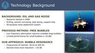
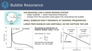
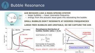
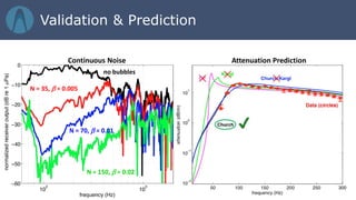
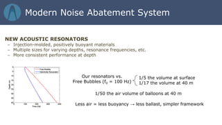
9/28/2015Mark S. Wochner, Ph.D. | President & CEO
Advanced Approaches in Underwater Noise Abatement
Technology Background
BACKGROUND: OIL AND GAS NOISE
– Research started in 2009
– Drilling, seismic surveying, pipe laying, support ship
– All-purpose noise abatement system
PREVIOUS METHOD: FREE BUBBLES
– Low frequency attenuation requires unstable large bubbles
– Limited performance for small bubbles (~10 dB)
OUR APPROACH: BUBBLE RESONANCE
– Frequencies of interest: 30 Hz to 200 Hz
– Desired noise level reduction: >10 dB
AIR BEHAVES LIKE A MASS-SPRING SYSTEM
– larger bubbles → lower resonance frequency
– energy from the acoustic wave goes into resonating the bubble
SMALL BUBBLES DON’T RESONATE AT DESIRED FREQUENCIES
LARGE FREE BUBBLES ARE UNSTABLE, SO WE CAPTURE THE AIR
Bubble Resonance
Commander & Prosperetti,
JASA 85, 732-746 (1989)
Monodisperse distribution of
bubbles: Bubble radius = 6 cm
Void fraction β = 0.01
Church, JASA 97, 1510-1521 (1995)
AIR BEHAVES LIKE A MASS-SPRING SYSTEM
– larger bubbles → lower resonance frequency
– energy from the acoustic wave goes into resonating the bubble
SMALL BUBBLES DON’T RESONATE AT DESIRED FREQUENCIES
LARGE FREE BUBBLES ARE UNSTABLE, SO WE CAPTURE THE AIR
a0 = 12 cm
a0 = 8.02
a0 = 6 cm Fixed Void
Fraction: 0.5%
0.5%
1%
2%
Fixed radius:
a0 = 8.02 cm
Two unique controls:
Control target
frequencies
Control amount of
attenuation
Bubble Resonance
SOURCES OF ENERGY DISSIPATION
– Heat transfer from gas inside resonator to surrounding fluid
– Work done by the resonator:
o Viscous losses in surrounding fluid
o Viscoelastic stresses in shell (fully or partly encapsulated resonators)
o Re-radiation of acoustic energy (phase incoherent)
 energy from sound wave goes into oscillating the resonator
 dominant loss mechanism for large resonators
NOTE: Higher Q resonators are better oscillators and better attenuators
Energy Losses
Acoustic Demonstration
Demonstration Video: Low-Frequency Version
(For High-Fidelity Sound Systems)
http://youtu.be/sKf4ibzJ-Jc
Demonstration Video: High-Frequency Version
(For Laptop Speakers, etc)
http://youtu.be/BHupQqkx3Hk
no bubbles
N = 150, β = 0.02
N = 70
β = 0.01
N = 35
β = 0.005
a0 = 8 cm
Results of lake tests in 35 m of water for continuous and impulsive noise
N = 35, β = 0.005
N = 70, β = 0.01
N = 150, β = 0.02
no bubbles
Continuous Noise Impulsive Noise
Validation
N = 35, β = 0.005
N = 70, β = 0.01
N = 150, β = 0.02
no bubbles
Continuous Noise Attenuation Prediction
Validation & Prediction
Helmholtz resonators’ behavior is dependent on a number of factors:
volume, neck length, and aperture size
Helmholtz resonance is often used in sound suppression:
Bass Traps
Car exhaust systems
Vair
L
A
Water
ADVANTAGES:
– More customizable & predictable
– Better performance at depth
– More rigging & manufacturing options available
– Lower ballast requirements
Helmholtz Resonance
2014 Demo Panel
Noise Abatement Concept
Close up of system on
articulating pile gripper
System deployed
around pile under
pile gripper
Noise Abatement Concept
2014 Demo Panel
RECENTLY COMPLETED OFFSHORE DEMONSTRATION
– Butendiek Wind Farm
– Monopile diameter: 6.8 m
– Project developer: WPD
– Installation company: Ballast Nedam
– Crew, vessel, support supplied by Ballast Nedam
– Three AdBm personnel involved in test
INSTALLATION OF SYSTEM IN NORTH SEA
– Four installations of the noise abatement system occurred
– No installation issues; fast deployment
Offshore Demonstration
The IHC Merwede NMS
Three different resonator sizes
Offshore Demonstration
Deployed system in the water Experimental setup
Offshore Demonstration
Without Noise Abatement
With Noise Abatement
Pile Range (m) Number of Strikes Baseline (dB) Panel (dB) Difference (dB) Max Reduction (dB)
BU-21 285 668 183.3 ± 0.7 164.2 ± 2.3 19.2 ± 2.4* 36.8*
Offshore Demonstration
NEW ACOUSTIC RESONATORS
– Injection-molded, positively buoyant materials
– Multiple sizes for varying depths, resonance frequencies, etc.
– More consistent performance at depth
Our resonators vs.
Free Bubbles (f0 = 100 Hz)
1/5 the volume at surface
1/17 the volume at 40 m
Less air = less buoyancy → less ballast, simpler framework
Modern Noise Abatement System
1/50 the air volume of balloons at 40 m
440 kg static load tested Slight plastic deformation afterward
NEW ACOUSTIC RESONATORS
Modern Noise Abatement System
RESONATOR FRAMEWORK
– Fully protected within metal deployment framework
– Framework organized as slats
– System stacks like Venetian blinds
– Resonator slats open below surface
– Functional elements protected
Aluminum/Steel
Framework
Chain guides
Resonators fully protected when slats are stacked
Modern Noise Abatement System
THE ASSEMBLED SYSTEM
– Panels arranged around pile and deployed using winches
– Mounted to pile gripper or directly to vessel
– Complete, tunable, passive system
SystemSlats
Resonators
Modern Noise Abatement System
SEISMIC SURVEYING
– metal Helmholtz resonators perform best
– well-suited to air gun noise abatement
– system of towed bodies can be designed
SHIPPING & DREDGING NOISE
– ship treated directly with hydrodynamic system
– system of fencing can be used to protect an area
– long-term, no energy solution
EXPLOSIVES
– UXO removal, explosive demolitions
(End View)
Noise abatement panels
Airgun
Noise abatement panels
Airgun
(End View)
Acoustic resonator
system absorption
Other Applications
Acoustic resonator systems have tunable, predictable performance
System has demonstrated up to 50 dB of noise reduction
New resonator design is more robust, easier to manufacture, has
better depth performance, and requires 25% the ballast
Can be used to treat other noise sources: ships, air guns, explosives
Summary

AdBm Overview Presentation 2015-09 Links

  • 1.
    9/28/2015Mark S. Wochner,Ph.D. | President & CEO Advanced Approaches in Underwater Noise Abatement
  • 2.
    Technology Background BACKGROUND: OILAND GAS NOISE – Research started in 2009 – Drilling, seismic surveying, pipe laying, support ship – All-purpose noise abatement system PREVIOUS METHOD: FREE BUBBLES – Low frequency attenuation requires unstable large bubbles – Limited performance for small bubbles (~10 dB) OUR APPROACH: BUBBLE RESONANCE – Frequencies of interest: 30 Hz to 200 Hz – Desired noise level reduction: >10 dB
  • 3.
    AIR BEHAVES LIKEA MASS-SPRING SYSTEM – larger bubbles → lower resonance frequency – energy from the acoustic wave goes into resonating the bubble SMALL BUBBLES DON’T RESONATE AT DESIRED FREQUENCIES LARGE FREE BUBBLES ARE UNSTABLE, SO WE CAPTURE THE AIR Bubble Resonance Commander & Prosperetti, JASA 85, 732-746 (1989) Monodisperse distribution of bubbles: Bubble radius = 6 cm Void fraction β = 0.01
  • 4.
    AIR BEHAVES LIKEA MASS-SPRING SYSTEM – larger bubbles → lower resonance frequency – energy from the acoustic wave goes into resonating the bubble SMALL BUBBLES DON’T RESONATE AT DESIRED FREQUENCIES LARGE FREE BUBBLES ARE UNSTABLE, SO WE CAPTURE THE AIR Bubble Resonance Commander & Prosperetti, JASA 85, 732-746 (1989) Monodisperse distribution of bubbles: Bubble radius = 6 cm Void fraction β = 0.01 Church, JASA 97, 1510-1521 (1995)
  • 5.
    AIR BEHAVES LIKEA MASS-SPRING SYSTEM – larger bubbles → lower resonance frequency – energy from the acoustic wave goes into resonating the bubble SMALL BUBBLES DON’T RESONATE AT DESIRED FREQUENCIES LARGE FREE BUBBLES ARE UNSTABLE, SO WE CAPTURE THE AIR a0 = 12 cm a0 = 8.02 a0 = 6 cm Fixed Void Fraction: 0.5% 0.5% 1% 2% Fixed radius: a0 = 8.02 cm Two unique controls: Control target frequencies Control amount of attenuation Bubble Resonance
  • 6.
    SOURCES OF ENERGYDISSIPATION – Heat transfer from gas inside resonator to surrounding fluid – Work done by the resonator: o Viscous losses in surrounding fluid o Viscoelastic stresses in shell (fully or partly encapsulated resonators) o Re-radiation of acoustic energy (phase incoherent)  energy from sound wave goes into oscillating the resonator  dominant loss mechanism for large resonators NOTE: Higher Q resonators are better oscillators and better attenuators Energy Losses
  • 7.
    Acoustic Demonstration Demonstration Video:Low-Frequency Version (For High-Fidelity Sound Systems) http://youtu.be/sKf4ibzJ-Jc Demonstration Video: High-Frequency Version (For Laptop Speakers, etc) http://youtu.be/BHupQqkx3Hk
  • 8.
    no bubbles N =150, β = 0.02 N = 70 β = 0.01 N = 35 β = 0.005 a0 = 8 cm Results of lake tests in 35 m of water for continuous and impulsive noise N = 35, β = 0.005 N = 70, β = 0.01 N = 150, β = 0.02 no bubbles Continuous Noise Impulsive Noise Validation
  • 9.
    N = 35,β = 0.005 N = 70, β = 0.01 N = 150, β = 0.02 no bubbles Continuous Noise Attenuation Prediction Validation & Prediction
  • 10.
    Helmholtz resonators’ behavioris dependent on a number of factors: volume, neck length, and aperture size Helmholtz resonance is often used in sound suppression: Bass Traps Car exhaust systems Vair L A Water ADVANTAGES: – More customizable & predictable – Better performance at depth – More rigging & manufacturing options available – Lower ballast requirements Helmholtz Resonance
  • 11.
    2014 Demo Panel NoiseAbatement Concept
  • 12.
    Close up ofsystem on articulating pile gripper System deployed around pile under pile gripper Noise Abatement Concept 2014 Demo Panel
  • 13.
    RECENTLY COMPLETED OFFSHOREDEMONSTRATION – Butendiek Wind Farm – Monopile diameter: 6.8 m – Project developer: WPD – Installation company: Ballast Nedam – Crew, vessel, support supplied by Ballast Nedam – Three AdBm personnel involved in test INSTALLATION OF SYSTEM IN NORTH SEA – Four installations of the noise abatement system occurred – No installation issues; fast deployment Offshore Demonstration
  • 14.
  • 15.
    Three different resonatorsizes Offshore Demonstration
  • 16.
    Deployed system inthe water Experimental setup Offshore Demonstration
  • 17.
    Without Noise Abatement WithNoise Abatement Pile Range (m) Number of Strikes Baseline (dB) Panel (dB) Difference (dB) Max Reduction (dB) BU-21 285 668 183.3 ± 0.7 164.2 ± 2.3 19.2 ± 2.4* 36.8* Offshore Demonstration
  • 18.
    NEW ACOUSTIC RESONATORS –Injection-molded, positively buoyant materials – Multiple sizes for varying depths, resonance frequencies, etc. – More consistent performance at depth Our resonators vs. Free Bubbles (f0 = 100 Hz) 1/5 the volume at surface 1/17 the volume at 40 m Less air = less buoyancy → less ballast, simpler framework Modern Noise Abatement System 1/50 the air volume of balloons at 40 m
  • 19.
    440 kg staticload tested Slight plastic deformation afterward NEW ACOUSTIC RESONATORS Modern Noise Abatement System
  • 20.
    RESONATOR FRAMEWORK – Fullyprotected within metal deployment framework – Framework organized as slats – System stacks like Venetian blinds – Resonator slats open below surface – Functional elements protected Aluminum/Steel Framework Chain guides Resonators fully protected when slats are stacked Modern Noise Abatement System
  • 21.
    THE ASSEMBLED SYSTEM –Panels arranged around pile and deployed using winches – Mounted to pile gripper or directly to vessel – Complete, tunable, passive system SystemSlats Resonators Modern Noise Abatement System
  • 22.
    SEISMIC SURVEYING – metalHelmholtz resonators perform best – well-suited to air gun noise abatement – system of towed bodies can be designed SHIPPING & DREDGING NOISE – ship treated directly with hydrodynamic system – system of fencing can be used to protect an area – long-term, no energy solution EXPLOSIVES – UXO removal, explosive demolitions (End View) Noise abatement panels Airgun Noise abatement panels Airgun (End View) Acoustic resonator system absorption Other Applications
  • 23.
    Acoustic resonator systemshave tunable, predictable performance System has demonstrated up to 50 dB of noise reduction New resonator design is more robust, easier to manufacture, has better depth performance, and requires 25% the ballast Can be used to treat other noise sources: ships, air guns, explosives Summary