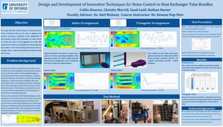
Acoustic Resonance is the intense noise that can be
heard from a heat exchanger during operation. Reso-
nance is the phenomena of the exciting frequency
synchronizing with the natural frequency . Acoustic
describes the type of resonance, sound. The exciting
frequency is caused by Vortex shedding. This hap-
pens when a flow is disrupted by the heat exchanger
tubes. This disruption causes small vortexes to form
behind the tubes. The frequency at which the vortex-
es occur is the exciting frequency. The frequency is
called Vortex Shedding Frequency.
The acoustic resonance from heat exchangers can be
dangerous. The sound can be very intense and would
require the use of hearing protection which could
prevent those performing maintenance or observing
the piece of equipment from hearing alarms or other
forms of communication. This can present an unsafe
work environment or a loss of profit due to the shut-
ting down of the system.
Problem Background
Objective
The main objective of this project is to develop inno-
vative techniques that can be used to suppress the
acoustic resonance excitation in the application of
tube bundles within heat exchangers. In other words
to reduce the noise. It was suggested to us that this
suppression could be accomplished by disrupting the
flow pattern of the fluid flowing around the heat ex-
changer tubes with the introduction of fluid into the
flow stream.
Test Procedure
Test 1—Airflow velocity correlation to motor frequency
by measuring stagnation pressure
Test 2—Baseline Noise Measurements
Measure noise level and locate resonance airflow by Var-
ying motor rotation frequency and measure noise level
Test 3 -Noise reduction via suppression system
Vary injection pressure and measure noise level
Results
Inline Arrangement Triangular Arrangement
Initial Unmodified Array (Before) Initial Unmodified Array (Before)
Collin Bourne, Christie Merrill, Saad Latif, Nathan Barter
Faculty Advisor: Dr. Atef Mohany Course Instructor: Dr. Remon Pop-Iliev
-0.70
-0.65
-0.60
-0.55
-0.50
-0.45
-0.40
-0.35
-0.30
-0.25
-0.20
-0.15
-0.10
0.00 0.10 0.20 0.30 0.40 0.50 0.60 0.70 0.80 0.90 1.00 1.10 1.20 1.30 1.40 1.50 1.60
cl
Flow Time (s)
Lift Convergence
-0.080
-0.070
-0.060
-0.050
-0.040
-0.030
-0.020
-0.010
0.000
0.010
0.020
0.030
0.040
0.050
0.060
0.070
0.00 0.10 0.20 0.30 0.40 0.50 0.60 0.70 0.80 0.90 1.00 1.10 1.20 1.30 1.40 1.50
cl
Flow Time(s)
Lift Convergence
-0.07
-0.05
-0.03
-0.01
0.02
0.00 0.10 0.20 0.30 0.40 0.50 0.60 0.70 0.80 0.90 1.00 1.10 1.20
cl
FlowTime(s)
Lift Convergence
-0.65
-0.60
-0.55
-0.50
-0.45
-0.40
-0.35
-0.30
-0.25
-0.20
0.00 0.10 0.20 0.30 0.40 0.50 0.60 0.70 0.80 0.90 1.00 1.10 1.20
cl
Flow Time(s)
Lift Convergence
Test Method
Initial simulation was done to show reso-
nance at certain operating conditions. The
injection system was then added and dif-
ferent hole arrangements were simulated.
The final results are shown below
The results for the inline and trian-
gular show that for inline the vertical
holes provide a solution and for tri-
angular horizontal provide better
solution.
Solution (After) Solution (After)
In-lined Array:
The results show that adding vertical holes will de-
crease the sound amplitude whether or not we inject
air into the system.
Triangular: Array
Numerical results inconclusive , although a decrease
in noise was heard during testing. More testing needs
to be done for this arrangement to confirm the re-
sults.
Acknowledgements
We would like to thank Dr. Atef Mohany and his teaching assis-
tants Nadim Arafa and Omar Sadek for helping us with the set
up, testing, and access to the aeroacoustics lab.
We would also like to thank Mike Macleod and Hidayat Shahid
for the help in the construction if our prototype.
Vortex shedding frequency =7.912Hz Vortex shedding frequency = 10.549Hz
Vortex shedding frequency = 21.978Hz Vortex shedding frequency = 23.976Hz

Poster

  • 1.
    Acoustic Resonance isthe intense noise that can be heard from a heat exchanger during operation. Reso- nance is the phenomena of the exciting frequency synchronizing with the natural frequency . Acoustic describes the type of resonance, sound. The exciting frequency is caused by Vortex shedding. This hap- pens when a flow is disrupted by the heat exchanger tubes. This disruption causes small vortexes to form behind the tubes. The frequency at which the vortex- es occur is the exciting frequency. The frequency is called Vortex Shedding Frequency. The acoustic resonance from heat exchangers can be dangerous. The sound can be very intense and would require the use of hearing protection which could prevent those performing maintenance or observing the piece of equipment from hearing alarms or other forms of communication. This can present an unsafe work environment or a loss of profit due to the shut- ting down of the system. Problem Background Objective The main objective of this project is to develop inno- vative techniques that can be used to suppress the acoustic resonance excitation in the application of tube bundles within heat exchangers. In other words to reduce the noise. It was suggested to us that this suppression could be accomplished by disrupting the flow pattern of the fluid flowing around the heat ex- changer tubes with the introduction of fluid into the flow stream. Test Procedure Test 1—Airflow velocity correlation to motor frequency by measuring stagnation pressure Test 2—Baseline Noise Measurements Measure noise level and locate resonance airflow by Var- ying motor rotation frequency and measure noise level Test 3 -Noise reduction via suppression system Vary injection pressure and measure noise level Results Inline Arrangement Triangular Arrangement Initial Unmodified Array (Before) Initial Unmodified Array (Before) Collin Bourne, Christie Merrill, Saad Latif, Nathan Barter Faculty Advisor: Dr. Atef Mohany Course Instructor: Dr. Remon Pop-Iliev -0.70 -0.65 -0.60 -0.55 -0.50 -0.45 -0.40 -0.35 -0.30 -0.25 -0.20 -0.15 -0.10 0.00 0.10 0.20 0.30 0.40 0.50 0.60 0.70 0.80 0.90 1.00 1.10 1.20 1.30 1.40 1.50 1.60 cl Flow Time (s) Lift Convergence -0.080 -0.070 -0.060 -0.050 -0.040 -0.030 -0.020 -0.010 0.000 0.010 0.020 0.030 0.040 0.050 0.060 0.070 0.00 0.10 0.20 0.30 0.40 0.50 0.60 0.70 0.80 0.90 1.00 1.10 1.20 1.30 1.40 1.50 cl Flow Time(s) Lift Convergence -0.07 -0.05 -0.03 -0.01 0.02 0.00 0.10 0.20 0.30 0.40 0.50 0.60 0.70 0.80 0.90 1.00 1.10 1.20 cl FlowTime(s) Lift Convergence -0.65 -0.60 -0.55 -0.50 -0.45 -0.40 -0.35 -0.30 -0.25 -0.20 0.00 0.10 0.20 0.30 0.40 0.50 0.60 0.70 0.80 0.90 1.00 1.10 1.20 cl Flow Time(s) Lift Convergence Test Method Initial simulation was done to show reso- nance at certain operating conditions. The injection system was then added and dif- ferent hole arrangements were simulated. The final results are shown below The results for the inline and trian- gular show that for inline the vertical holes provide a solution and for tri- angular horizontal provide better solution. Solution (After) Solution (After) In-lined Array: The results show that adding vertical holes will de- crease the sound amplitude whether or not we inject air into the system. Triangular: Array Numerical results inconclusive , although a decrease in noise was heard during testing. More testing needs to be done for this arrangement to confirm the re- sults. Acknowledgements We would like to thank Dr. Atef Mohany and his teaching assis- tants Nadim Arafa and Omar Sadek for helping us with the set up, testing, and access to the aeroacoustics lab. We would also like to thank Mike Macleod and Hidayat Shahid for the help in the construction if our prototype. Vortex shedding frequency =7.912Hz Vortex shedding frequency = 10.549Hz Vortex shedding frequency = 21.978Hz Vortex shedding frequency = 23.976Hz