The document discusses the evolution and functionalities of conventional cruise control and adaptive cruise control (ACC) systems in vehicles. While conventional cruise control maintains a constant speed set by the driver, ACC enhances this by automatically adjusting speed to maintain a safe distance from other vehicles. It outlines key components, benefits, limitations, and includes a simulation model for the ACC system using model predictive control strategies.


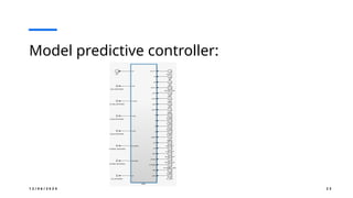


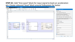
![STEP 4 : Search for “Transfer Fcn” in library Browser, drag It and Double
left click on it to configure the Tranfer Fcn block. Here the Num, Den
coefficient is [1] and [0.5 1 ]
S I M U L I N K M O D E L F O R L E A D A N D E G O C A R](https://image.slidesharecdn.com/adaptivecruisecontrol1-241206062326-a414b91c/85/Adaptive-cruise-control-using-model-predictive-controller-and-matlab-simulation-results-38-320.jpg)


![[English Version]Maker-Ray Product Brochure V3 .pdf](https://cdn.slidesharecdn.com/ss_thumbnails/englishversionmaker-rayproductbrochurev3-260113094444-0156dbdc-thumbnail.jpg?width=640&height=640&fit=bounds)


![DESIGN AND FABRICATION OF THE IBM 90-90 SEAT BELT CLAMP KIA VEHICLE[1].pptx 2...](https://cdn.slidesharecdn.com/ss_thumbnails/designandfabricationoftheibm90-90seatbeltclampkiavehicle1-260116160442-70ff67fc-thumbnail.jpg?width=640&height=640&fit=bounds)


