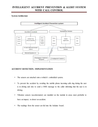
The document presents an intelligent accident prevention and alert system designed to reduce vehicle accidents, primarily caused by distractions such as mobile phone usage while driving. It outlines the system's objectives to eliminate distractions from incoming calls and to automatically notify emergency contacts with location data in the event of an accident. Additionally, it provides an overview of the Android platform's capabilities, emphasizing features that support the development of mobile applications aimed at enhancing vehicle safety and communication.

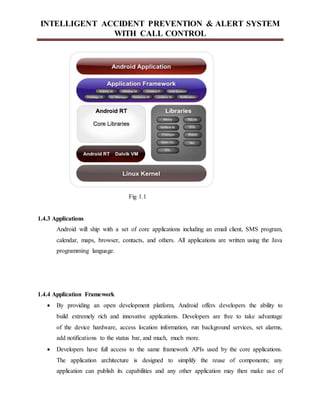
![INTELLIGENT ACCIDENT PREVENTION & ALERT SYSTEM
WITH CALL CONTROL
2. Kodanda Ramaiah GN et al., [3] proposed a smart helmet idea which provided a lot of
functionalities. These include cooling the inside of a helmet using a thermoelectric cooler
working on solar energy; Bluetooth headset inside the helmet to handle calls; ensuring that the
rider is wearing a helmet while on a trip; GPS and GSM modules to send the precise location of
the rider in case of an accident. The smart helmet idea here has two modules – helmet and the
two-wheeler. The helmet module consists of the solar strips, Bluetooth headphones,
thermoelectric cooler, ignition control switch and an RF Transmitter. The vehicle module on the
other hand consists of the GSM, GPS, vibration sensor, RF Receiver and a microcontroller. The
solar strips are used to power up all the peripherals interfaced into the helmet. The RF
Transmitter sends the trigger signals about the status of switches to the vehicle module. When
the RF receiver receives an alert signal from the helmet module, the same is sent to the controller
to take necessary actions. The vibration sensor along with the GSM and GPS modules work
together with the microcontroller to send alerts regarding an accident to the specified contacts
and emergency vehicles/hospitals. While this helmet provides a lot of important functionalities it
has two major problems – one, is the infeasibility of the system due to the ignition system having
to be tampered with, in every single model of every single two-wheeler manufacturer and two,
the final cost of the helmet going high due to fancy add-ons like a thermoelectric cooler.
3. Indranil Nikose et al., [6] proposed a smart helmet idea which focused on two features:
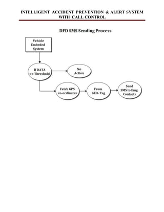
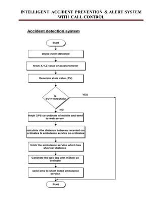
The detection of an accident using an accelerometer sensor, GPS and GSM modules, and
prevention of accidents by the detection of alcohol levels of the rider using an alcohol sensor.
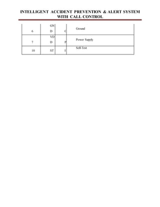
The working of accident detection is fairly simple. When the helmet hits the ground, the
accelerometer sensors note this data and send it to a CMOS 8-bit microcontroller. The controller
then extracts the longitude and latitude of the location using the GPS module and initiates a timer
counting to 10 minutes. If the rider doesn’t start riding in those 10 minutes then the controller
sends the location details as an SMS to the ambulance and parents. The alcohol is detected using
an alcohol sensor which measures the amount of alcohol present in the surrounding environment.
When the alcohol level crosses a predefined value, it triggers off an alarm, notifying the makers.](https://image.slidesharecdn.com/fullreportaps-210409104020/85/Accident-detection-10-320.jpg)


![INTELLIGENT ACCIDENT PREVENTION & ALERT SYSTEM
WITH CALL CONTROL
Chapter 9
BIBLIOGRAPHY
[1] Effective Ways to Use Internet of Things in the field of Medical and Smart Health Care:
Kaleem ullah, Munam ali Shah, Sijing zhang, IEEE Journal 2016.
[2] Heartbeat Monitoring and heart attack detection, Mamidi manisha , Katakan neeraja,
International Journal of Innovations in Engineering and Technology(IJIET).
[3]Heartbeat Sensing and Heart Attack Detection using Internet of Things, International Journal
of Engineering Science and Computing(IJESC).
[4]Heart Rate monitoring And Heart Attack Detection Using Wearable Device, International
Journal of Technical Research and Application(IJTRA).
[5] Mobile based Horne Automation using Internet of Things(IOT),Kumar Mandula, Ram
Parupalli, E.Magesh,2015 International Conference on Control, Instrumentation,](https://image.slidesharecdn.com/fullreportaps-210409104020/85/Accident-detection-64-320.jpg)


![[Deck] What's New in Spark-Iceberg Integration via DSV2.pptx](https://cdn.slidesharecdn.com/ss_thumbnails/deckwhatsnewinspark-icebergintegrationviadsv2-260210005337-25955b12-thumbnail.jpg?width=640&height=640&fit=bounds)


