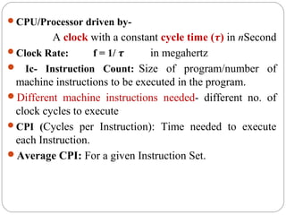
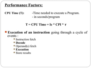
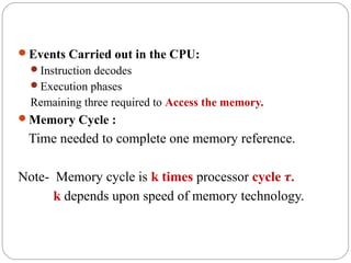
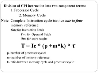
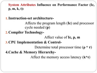
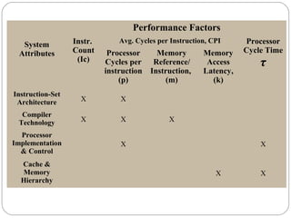
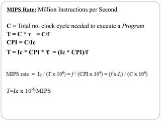
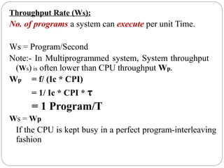
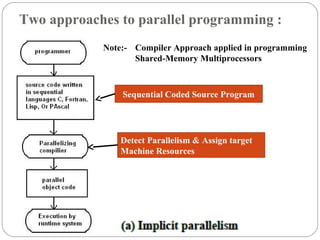
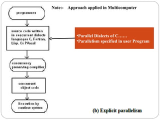
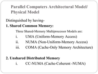
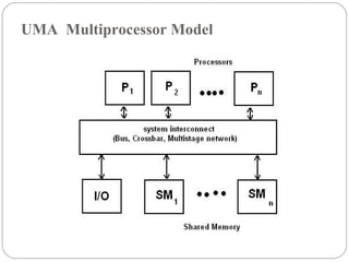
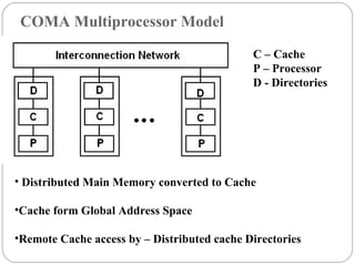
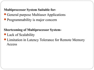
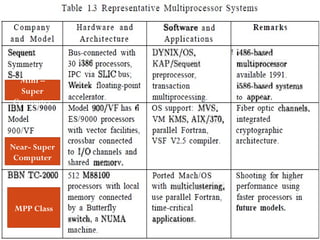
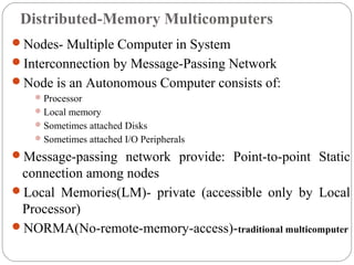
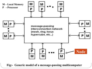
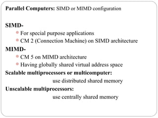
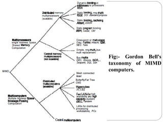
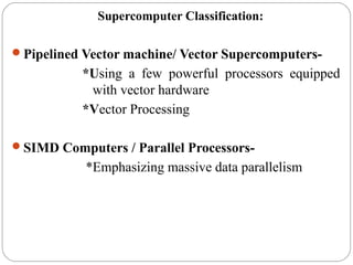
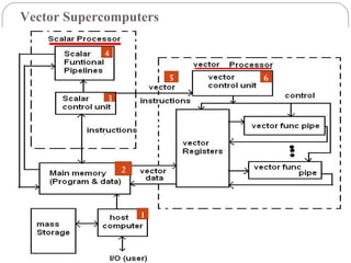
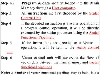
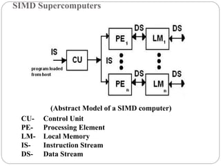
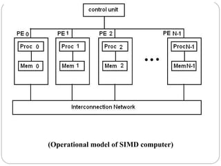
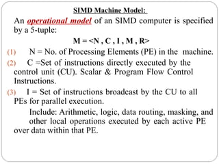
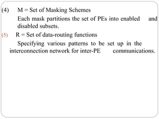
System Attributes to
Performance
22/9/2012
CPU/Processor driven by-
A clock with a constant cycle time (τ) in nSecond
Clock Rate: f = 1/ τ in megahertz
 Ic- Instruction Count: Size of program/number of
machine instructions to be executed in the program.
Different machine instructions needed- different no. of
clock cycles to execute
CPI (Cycles per Instruction): Time needed to execute
each Instruction.
Average CPI: For a given Instruction Set.
Performance Factors:
CPU Time (T): -Time needed to execute a Program.
- in seconds/program
T = CPU Time = Ic * CPI * τ
Execution of an instruction going through a cycle of
events :
Instruction fetch
Decode
Operand(s) fetch
Execution
Store results
Events Carried out in the CPU:
Instruction decodes
Execution phases
Remaining three required to Access the memory.
Memory Cycle :
Time needed to complete one memory reference.
Note- Memory cycle is k times processor cycle τ.
k depends upon speed of memory technology.
System Attributes Influence on Performance Factor (Ic,
p, m, k, t):
1.Instruction-set architecture-
Affects the program length (Ic) and processor
cycle needed (p)
2.Compiler Technology-
Affect value of Ic, p, m
3.CPU Implementation & Control-
Determine total processor time (p * τ)
4.Cache & Memory Hierarchy-
Affect the memory access latency (k*τ)
System
Attributes
Performance Factors
Instr.
Count
(Ic)
Avg. Cycles per Instruction, CPI Processor
Cycle Time
τ
Processor
Cycles per
instruction
(p)
Memory
Reference/
Instruction,
(m)
Memory
Access
Latency,
(k)
Instruction-Set
Architecture X X
Compiler
Technology X X X
Processor
Implementation
& Control
X X
Cache &
Memory
Hierarchy
X X
MIPS Rate: Million Instructions per Second
C = Total no. clock cycle needed to execute a Program
T = C * τ = C/f
CPI = C/Ic
T = Ic * CPI * τ = (Ic * CPI)/f
Throughput Rate (Ws):
No. of programs a system can execute per unit Time.
Ws = Program/Second
Note:- In Multiprogrammed system, System throughput
(Ws) is often lower than CPU throughput Wp.
Wp = f/ (Ic * CPI)
= 1/ Ic * CPI * τ
= 1 Program/T
Ws = Wp
If the CPU is kept busy in a perfect program-interleaving
fashion
Two approaches to parallel programming :
Sequential Coded Source Program
Detect Parallelism & Assign target
Machine Resources
Note:- Compiler Approach applied in programming
Shared-Memory Multiprocessors
•Parallel Dialects of C……
•Parallelism specified in user Program
Note:- Approach applied in Multicomputer
Parallel Computers Architectural Model/
Physical Model
Distinguished by having-
1. Shared Common Memory:
Three Shared-Memory Multiprocessor Models are:
i. UMA (Uniform-Memory Access)
ii. NUMA (Non-Uniform-Memory Access)
iii. COMA (Cache-Only Memory Architecture)
2. Unshared Distributed Memory
i. CC-NUMA (Cache-Coherent -NUMA)
UMA Multiprocessor Model
Physical memory is uniformly shared by all the
processors.
All Processors have equal access time to all memory
words, so it is called Uniform Memory Access.
Peripherals are also shared in some fashion.
Also called Tightly Coupled Systems -due to the high
degree of resource sharing.
Symmetric Vs Asymmetric Multiprocessor
Symmetric Multiprocessor: All processors have equal
access to all peripheral devices.
Asymmetric Multiprocessor:
Only one or a subset of processors are executive capable.
i. MP (Executive or Master Processor)-
Can execute the O.S. and handle I/O
ii. AP (Attached Processor)-
No I/O capability
AP execute user codes under Supervision of MP
NUMA Multiprocessor Model
Shared-Memory System
Access Time varies with the location of the Memory
Word
Local Memories (LM): Shared Memory is physically
distributed to all processors
Global Address Space: Forms by collection of all
Local Memories (LM) that is accessible by all
processors.
Faster Access to a local memory with a local processor
Slow Access to remote memory attached to other
processors due to the added delay through the
interconnection network
LM – Local Memory
P - Local Processor
P – Processor
CSM – Cluster Shared Memory
CIN – Cluster Interconnection Network
GSM – Global Shared Memory
UMA or
NUMA
(Access of Remote Memory)
Three Memory-Access Patterns when Globally Shared
Memory (GSM) added to a multiprocessor system:
i. The fastest is Local Memory(LM) access
ii. The next is global memory (GSM)access
iii. The slowest is access of Remote Memory
Remote Memory- LM attach to other processor
Note:
All cluster have equal access to GSM
Access right among Intercluster memories can be specified.
COMA Multiprocessor Model
• Distributed Main Memory converted to Cache
•Cache form Global Address Space
•Remote Cache access by – Distributed cache Directories
C – Cache
P – Processor
D - Directories
Multiprocessor System Suitable for-
General purpose Multiuser Applications
Programmability is major concern
Shortcoming of Multiprocessor System-
Lack of Scalability
Limitation in Latency Tolerance for Remote Memory
Access
Mini –
Super
Computer
Near- Super
Computer
MPP Class
Distributed-Memory Multicomputers
Nodes- Multiple Computer in System
Interconnection by Message-Passing Network
Node is an Autonomous Computer consists of:
Processor
Local memory
Sometimes attached Disks
Sometimes attached I/O Peripherals
Message-passing network provide: Point-to-point Static
connection among nodes
Local Memories(LM)- private (accessible only by Local
Processor)
NORMA(No-remote-memory-access)-traditional multicomputer
Fig:- Generic model of a message-passing multicomputer
M – Local Memory
P - Processor
Node
Parallel Computers: SIMD or MIMD configuration
SIMD-
For special purpose applications
CM 2 (Connection Machine) on SIMD architecture
MIMD-
CM 5 on MIMD architecture
Having globally shared virtual address space
Scalable multiprocessors or multicomputer:
use distributed shared memory
Unscalable multiprocessors:
use centrally shared memory
Fig:- Gordon Bell's
taxonomy of MIMD
computers.
Supercomputer Classification:
Pipelined Vector machine/ Vector Supercomputers-
*Using a few powerful processors equipped
with vector hardware
*Vector Processing
SIMD Computers / Parallel Processors-
*Emphasizing massive data parallelism
Vector Supercomputers
1
2
3
4
5 6
Step 1-2 Program & data are first loaded into the Main
Memory through a Host computer.
Step 3 All instructions are first decoded by the Scalar
Control Unit.
Step 4 If the decoded instruction is a scalar operation or
a program control operation, it will be directly
executed by the scalar processor using the Scalar
Functional Pipelines.
Step 5 If the instructions are decoded as a Vector
operation, it will be sent to the vector control
unit.
Step 6 Vector control unit will supervise the flow of
vector data between the main memory and vector
functional pipelines.
Note: A number of vector functional pipelines may be built into a
SIMD Supercomputers
CU- Control Unit
PE- Processing Element
LM- Local Memory
IS- Instruction Stream
DS- Data Stream
(Abstract Model of a SIMD computer)
(Operational model of SIMD computer)
SIMD Machine Model:
An operational model of an SIMD computer is specified
by a 5-tuple:
M = <N , C , I , M , R>
(1) N = No. of Processing Elements (PE) in the machine.
(2) C =Set of instructions directly executed by the
control unit (CU). Scalar & Program Flow Control
Instructions.
(3) I = Set of instructions broadcast by the CU to all
PEs for parallel execution.
Include: Arithmetic, logic, data routing, masking, and
other local operations executed by each active PE
over data within that PE.
(4) M = Set of Masking Schemes
Each mask partitions the set of PEs into enabled and
disabled subsets.
(5) R = Set of data-routing functions
Specifying various patterns to be set up in the
interconnection network for inter-PE communications.

Aca 2

  • 1.
  • 2.
    CPU/Processor driven by- Aclock with a constant cycle time (τ) in nSecond Clock Rate: f = 1/ τ in megahertz  Ic- Instruction Count: Size of program/number of machine instructions to be executed in the program. Different machine instructions needed- different no. of clock cycles to execute CPI (Cycles per Instruction): Time needed to execute each Instruction. Average CPI: For a given Instruction Set.
  • 3.
    Performance Factors: CPU Time(T): -Time needed to execute a Program. - in seconds/program T = CPU Time = Ic * CPI * τ Execution of an instruction going through a cycle of events : Instruction fetch Decode Operand(s) fetch Execution Store results
  • 4.
    Events Carried outin the CPU: Instruction decodes Execution phases Remaining three required to Access the memory. Memory Cycle : Time needed to complete one memory reference. Note- Memory cycle is k times processor cycle τ. k depends upon speed of memory technology.
  • 6.
    System Attributes Influenceon Performance Factor (Ic, p, m, k, t): 1.Instruction-set architecture- Affects the program length (Ic) and processor cycle needed (p) 2.Compiler Technology- Affect value of Ic, p, m 3.CPU Implementation & Control- Determine total processor time (p * τ) 4.Cache & Memory Hierarchy- Affect the memory access latency (k*τ)
  • 7.
    System Attributes Performance Factors Instr. Count (Ic) Avg. Cyclesper Instruction, CPI Processor Cycle Time τ Processor Cycles per instruction (p) Memory Reference/ Instruction, (m) Memory Access Latency, (k) Instruction-Set Architecture X X Compiler Technology X X X Processor Implementation & Control X X Cache & Memory Hierarchy X X
  • 8.
    MIPS Rate: MillionInstructions per Second C = Total no. clock cycle needed to execute a Program T = C * τ = C/f CPI = C/Ic T = Ic * CPI * τ = (Ic * CPI)/f
  • 9.
    Throughput Rate (Ws): No.of programs a system can execute per unit Time. Ws = Program/Second Note:- In Multiprogrammed system, System throughput (Ws) is often lower than CPU throughput Wp. Wp = f/ (Ic * CPI) = 1/ Ic * CPI * τ = 1 Program/T Ws = Wp If the CPU is kept busy in a perfect program-interleaving fashion
  • 10.
    Two approaches toparallel programming : Sequential Coded Source Program Detect Parallelism & Assign target Machine Resources Note:- Compiler Approach applied in programming Shared-Memory Multiprocessors
  • 11.
    •Parallel Dialects ofC…… •Parallelism specified in user Program Note:- Approach applied in Multicomputer
  • 12.
    Parallel Computers ArchitecturalModel/ Physical Model Distinguished by having- 1. Shared Common Memory: Three Shared-Memory Multiprocessor Models are: i. UMA (Uniform-Memory Access) ii. NUMA (Non-Uniform-Memory Access) iii. COMA (Cache-Only Memory Architecture) 2. Unshared Distributed Memory i. CC-NUMA (Cache-Coherent -NUMA)
  • 13.
  • 14.
    Physical memory isuniformly shared by all the processors. All Processors have equal access time to all memory words, so it is called Uniform Memory Access. Peripherals are also shared in some fashion. Also called Tightly Coupled Systems -due to the high degree of resource sharing.
  • 15.
    Symmetric Vs AsymmetricMultiprocessor Symmetric Multiprocessor: All processors have equal access to all peripheral devices. Asymmetric Multiprocessor: Only one or a subset of processors are executive capable. i. MP (Executive or Master Processor)- Can execute the O.S. and handle I/O ii. AP (Attached Processor)- No I/O capability AP execute user codes under Supervision of MP
  • 16.
    NUMA Multiprocessor Model Shared-MemorySystem Access Time varies with the location of the Memory Word Local Memories (LM): Shared Memory is physically distributed to all processors Global Address Space: Forms by collection of all Local Memories (LM) that is accessible by all processors. Faster Access to a local memory with a local processor Slow Access to remote memory attached to other processors due to the added delay through the interconnection network
  • 17.
    LM – LocalMemory P - Local Processor
  • 18.
    P – Processor CSM– Cluster Shared Memory CIN – Cluster Interconnection Network GSM – Global Shared Memory UMA or NUMA (Access of Remote Memory)
  • 19.
    Three Memory-Access Patternswhen Globally Shared Memory (GSM) added to a multiprocessor system: i. The fastest is Local Memory(LM) access ii. The next is global memory (GSM)access iii. The slowest is access of Remote Memory Remote Memory- LM attach to other processor Note: All cluster have equal access to GSM Access right among Intercluster memories can be specified.
  • 20.
    COMA Multiprocessor Model •Distributed Main Memory converted to Cache •Cache form Global Address Space •Remote Cache access by – Distributed cache Directories C – Cache P – Processor D - Directories
  • 21.
    Multiprocessor System Suitablefor- General purpose Multiuser Applications Programmability is major concern Shortcoming of Multiprocessor System- Lack of Scalability Limitation in Latency Tolerance for Remote Memory Access
  • 22.
  • 23.
    Distributed-Memory Multicomputers Nodes- MultipleComputer in System Interconnection by Message-Passing Network Node is an Autonomous Computer consists of: Processor Local memory Sometimes attached Disks Sometimes attached I/O Peripherals Message-passing network provide: Point-to-point Static connection among nodes Local Memories(LM)- private (accessible only by Local Processor) NORMA(No-remote-memory-access)-traditional multicomputer
  • 24.
    Fig:- Generic modelof a message-passing multicomputer M – Local Memory P - Processor Node
  • 25.
    Parallel Computers: SIMDor MIMD configuration SIMD- For special purpose applications CM 2 (Connection Machine) on SIMD architecture MIMD- CM 5 on MIMD architecture Having globally shared virtual address space Scalable multiprocessors or multicomputer: use distributed shared memory Unscalable multiprocessors: use centrally shared memory
  • 26.
    Fig:- Gordon Bell's taxonomyof MIMD computers.
  • 27.
    Supercomputer Classification: Pipelined Vectormachine/ Vector Supercomputers- *Using a few powerful processors equipped with vector hardware *Vector Processing SIMD Computers / Parallel Processors- *Emphasizing massive data parallelism
  • 28.
  • 29.
    Step 1-2 Program& data are first loaded into the Main Memory through a Host computer. Step 3 All instructions are first decoded by the Scalar Control Unit. Step 4 If the decoded instruction is a scalar operation or a program control operation, it will be directly executed by the scalar processor using the Scalar Functional Pipelines. Step 5 If the instructions are decoded as a Vector operation, it will be sent to the vector control unit. Step 6 Vector control unit will supervise the flow of vector data between the main memory and vector functional pipelines. Note: A number of vector functional pipelines may be built into a
  • 30.
    SIMD Supercomputers CU- ControlUnit PE- Processing Element LM- Local Memory IS- Instruction Stream DS- Data Stream (Abstract Model of a SIMD computer)
  • 31.
    (Operational model ofSIMD computer)
  • 32.
    SIMD Machine Model: Anoperational model of an SIMD computer is specified by a 5-tuple: M = <N , C , I , M , R> (1) N = No. of Processing Elements (PE) in the machine. (2) C =Set of instructions directly executed by the control unit (CU). Scalar & Program Flow Control Instructions. (3) I = Set of instructions broadcast by the CU to all PEs for parallel execution. Include: Arithmetic, logic, data routing, masking, and other local operations executed by each active PE over data within that PE.
  • 33.
    (4) M =Set of Masking Schemes Each mask partitions the set of PEs into enabled and disabled subsets. (5) R = Set of data-routing functions Specifying various patterns to be set up in the interconnection network for inter-PE communications.