This document provides an overview of traction systems used for locomotives in Indian Railways. It discusses the classification codes used to identify locomotives based on gauge, power source, and intended use. Diesel locomotives commonly used include the WDM-2 and variants, with power ratings ranging from 2,600 to 5,500 hp. Electric locomotives vary from 2,800 to 6,350 hp and accommodate different track voltages. Early electric locomotives in Mumbai used 1,500 V DC, while most of India uses 25,000 V AC. A brief history of locomotives in India is also given, noting the transition from steam to diesel and electric starting in the 1950s.


![17
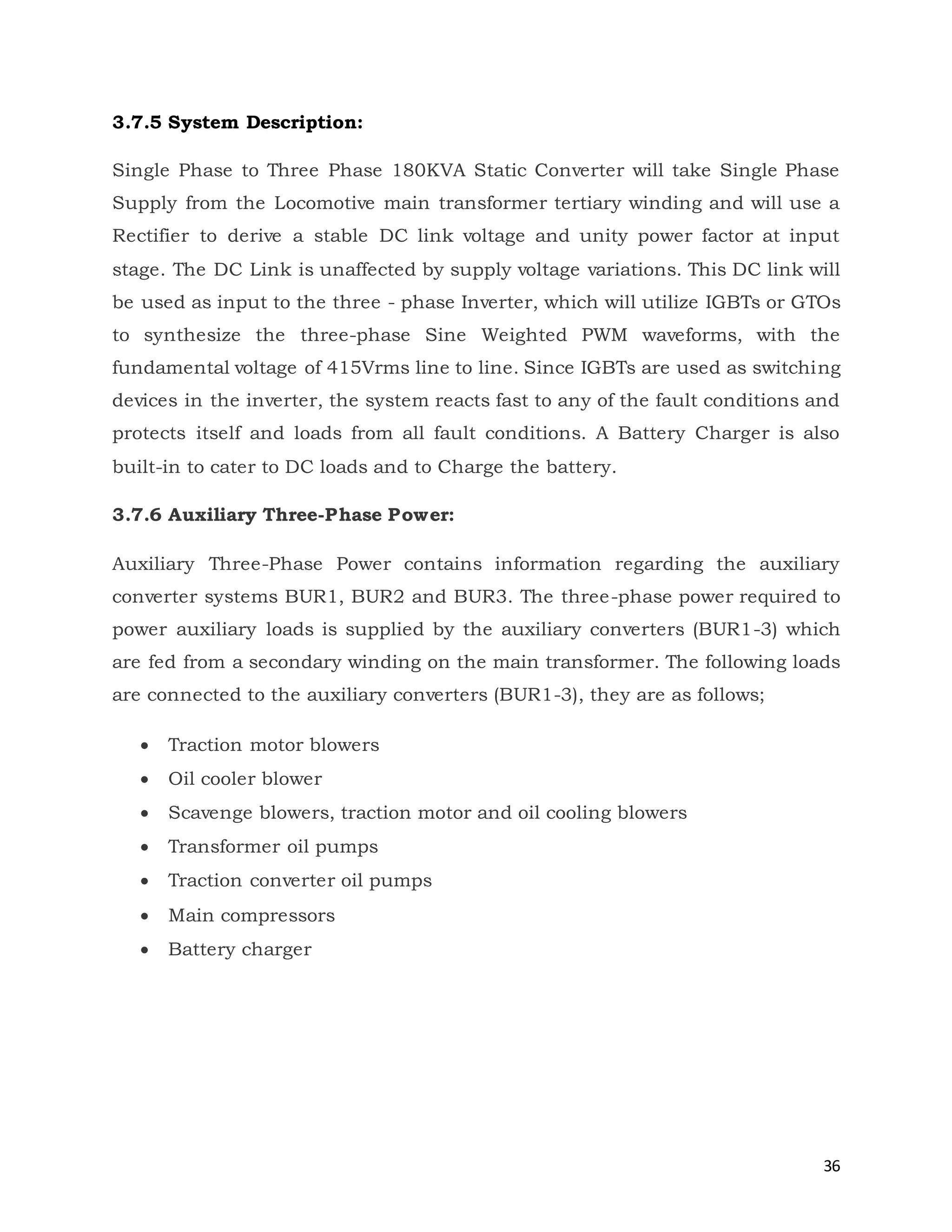
2.6 Overview of Traction Offerings:
Figure 3: Overview of Traction
[1] Traction transformer
[2] Traction converter
[3] Traction control
[4] Train Control and Monitoring System
[5] Traction motor
[6] Diesel engine generator
[7] Auxiliary converter
[8] Battery charger
[9] Energy storage
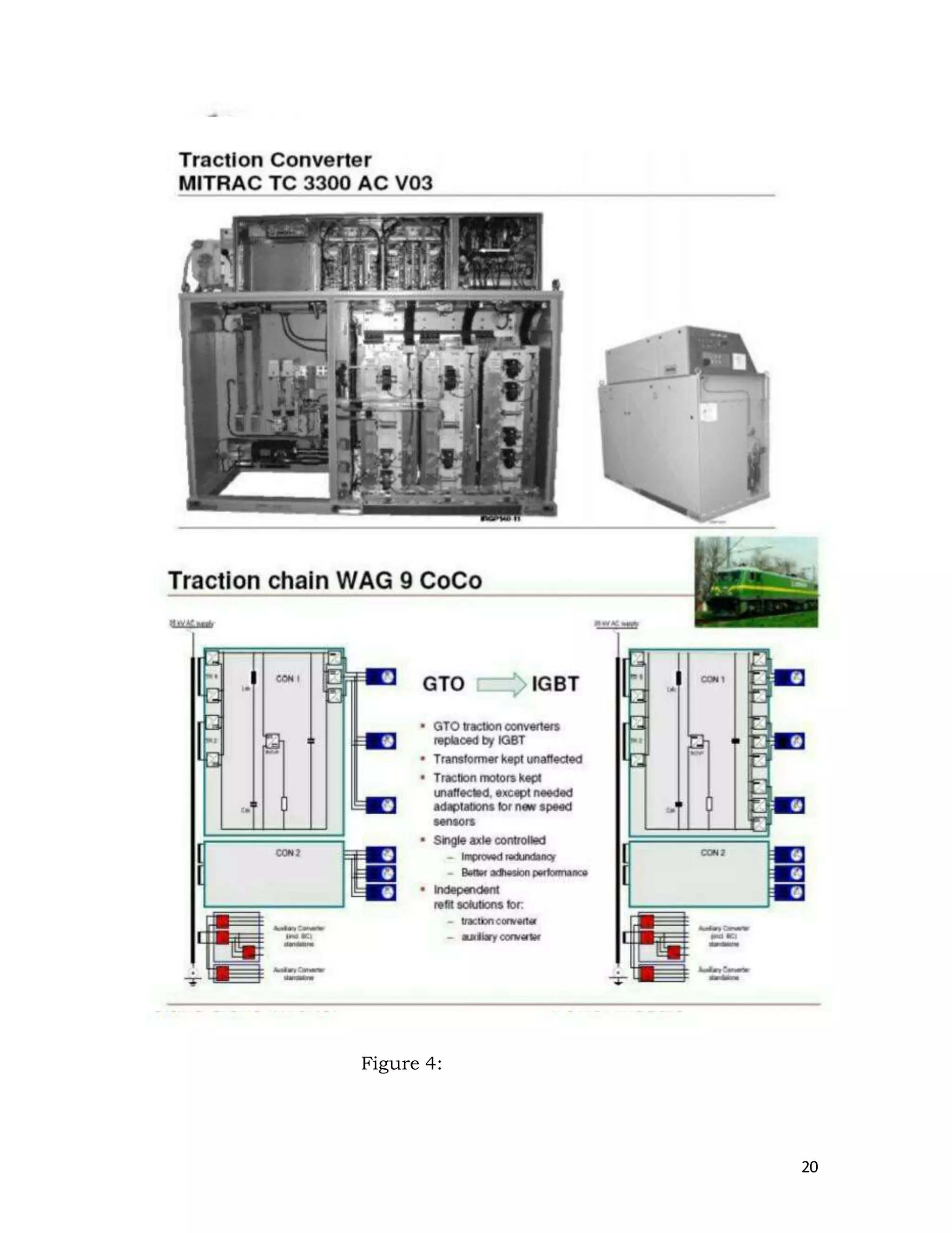
2.7 IGBT Traction Converter based Locomotive:
2.7 Introduction:
In the recent past, all over the world the trend has been to switch over
from conventional DC drives to 3-Phase AC drives based on the
Insulated Gate Bipolar Transistor (IGBT) technology. At present, the
flagship locomotive of Indian Railways is the 3-phase locomotive.
Presently, the different variants, viz, WAG9, WAG9H, WAP7 and WAP5 are](https://image.slidesharecdn.com/minireport1-170826062650/75/electric-loco-shed-lalllguda-17-2048.jpg)