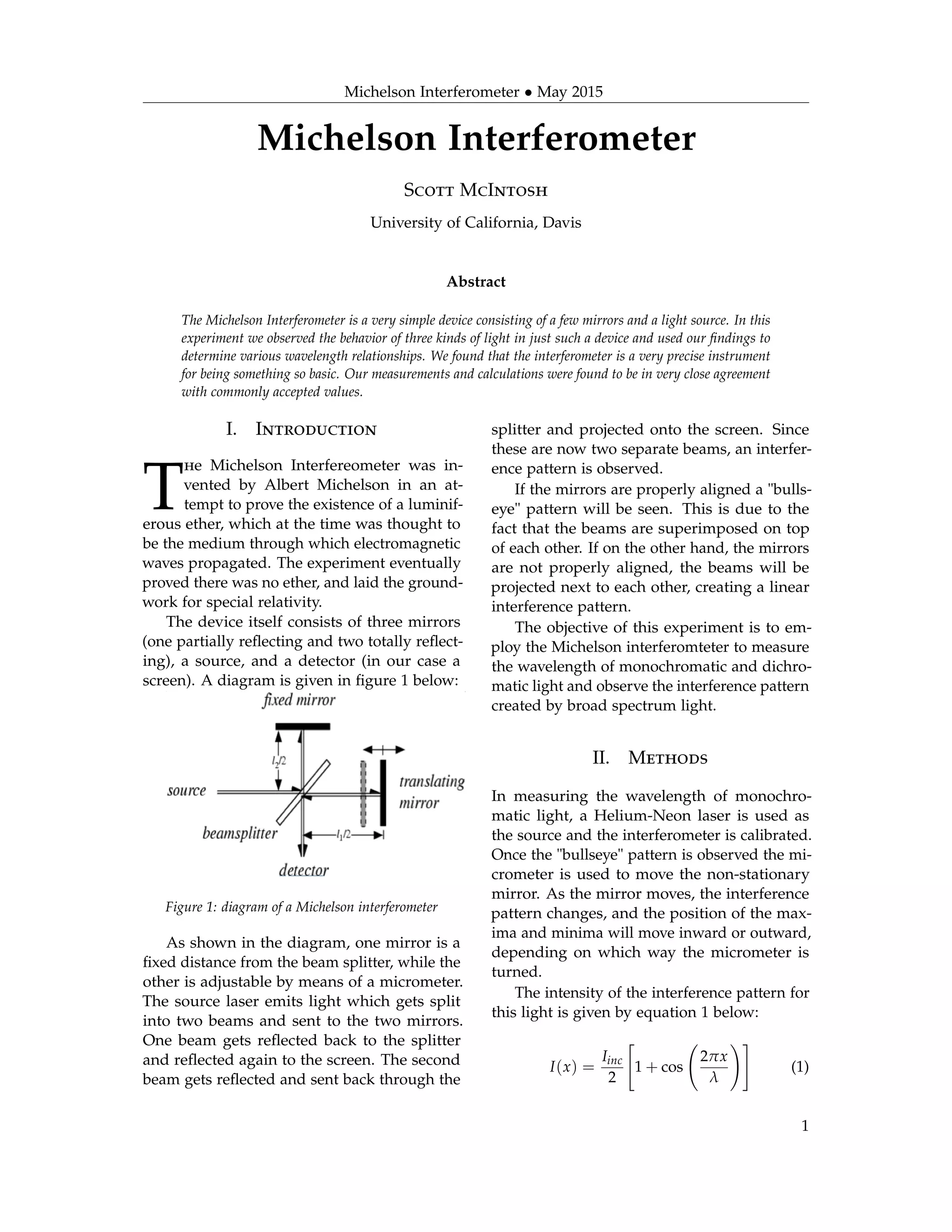
Michelson Interferometer • May 2015
Michelson Interferometer
Scott McIntosh
University of California, Davis
Abstract
The Michelson Interferometer is a very simple device consisting of a few mirrors and a light source. In this
experiment we observed the behavior of three kinds of light in just such a device and used our findings to
determine various wavelength relationships. We found that the interferometer is a very precise instrument
for being something so basic. Our measurements and calculations were found to be in very close agreement
with commonly accepted values.
I. Introduction
T
he Michelson Interfereometer was in-
vented by Albert Michelson in an at-
tempt to prove the existence of a luminif-
erous ether, which at the time was thought to
be the medium through which electromagnetic
waves propagated. The experiment eventually
proved there was no ether, and laid the ground-
work for special relativity.
The device itself consists of three mirrors
(one partially reflecting and two totally reflect-
ing), a source, and a detector (in our case a
screen). A diagram is given in figure 1 below:
Figure 1: diagram of a Michelson interferometer
As shown in the diagram, one mirror is a
fixed distance from the beam splitter, while the
other is adjustable by means of a micrometer.
The source laser emits light which gets split
into two beams and sent to the two mirrors.
One beam gets reflected back to the splitter
and reflected again to the screen. The second
beam gets reflected and sent back through the
splitter and projected onto the screen. Since
these are now two separate beams, an interfer-
ence pattern is observed.
If the mirrors are properly aligned a "bulls-
eye" pattern will be seen. This is due to the
fact that the beams are superimposed on top
of each other. If on the other hand, the mirrors
are not properly aligned, the beams will be
projected next to each other, creating a linear
interference pattern.
The objective of this experiment is to em-
ploy the Michelson interferomteter to measure
the wavelength of monochromatic and dichro-
matic light and observe the interference pattern
created by broad spectrum light.
II. Methods
In measuring the wavelength of monochro-
matic light, a Helium-Neon laser is used as
the source and the interferometer is calibrated.
Once the "bullseye" pattern is observed the mi-
crometer is used to move the non-stationary
mirror. As the mirror moves, the interference
pattern changes, and the position of the max-
ima and minima will move inward or outward,
depending on which way the micrometer is
turned.
The intensity of the interference pattern for
this light is given by equation 1 below:
I(x) =
Iinc
2
1 + cos
2πx
λ
(1)
1
Michelson Interferometer • May 2015
where x is the path difference between the
two mirrors.
We can see that the maxima and minima
occur when x is equal to an integer multiple
of λ. By turning the micrometer and cycling
the position of the maxima N times, and mea-
suring ∆x we can calculate the wavelength by
employing the following formula:
∆x = Nλ (2)
Due to the mechanical action of the inter-
nal parts of the interferometer, we must add a
scaling factor of 2
5 . Solving for λ we get:
2
5
∆x
N
= λ (3)
In measuring the wavelength of dichro-
matic light, a sodium lamp is used as the
source and the interferometer is calibrated.
Measurements are taken in the same manner
as monochromatic light.
The intensity of dichromatic light is given
by the sum of equations 4 and 5 below:
I1(x) =
Iinc(λ1)
2
1 + cos
2πx
λ1
(4)
I2(x) =
Iinc(λ2)
2
1 + cos
2πx
λ2
(5)
Ordinarily an intensity equation would re-
quire an interference cross-term, but since these
are two different wavelengths of light, no inter-
ference term is necessary. The intensity can be
approximated by the following equation:
I(x) ≈ Iinc(¯λ) 1 +cos
2πx
¯λ
cos
π(∆λ)x
¯λ2
(6)
where we define ¯λ and ∆λ as follows:
¯λ =
λ1 + λ2
s
(7)
∆λ =| λ1 − λ2 | (8)
By modifying equation 3 we can derive a
result for ¯λ:
2
5
∆x
N
= ¯λ (9)
Next we must determine the path difference
between the envelope maxima and minima. We
do this by finding how far the mirror must be
moved between points where the overall inten-
sity of the fringes drops to a minimum. We
shall refer to this distance as ∆x . By employ-
ing the following equation we can derive the
value for ∆λ
∆λ =
5¯λ2
∆x
(10)
In observing the interference pattern cre-
ated by broad spectrum light, we simply swap
out our previous sources for a white light and
calibrate the interferometer.
III. Results
For monochromatic light we measured ∆x to
be approximately 0.0044cm after N = 25 turns.
Using equation 3, we found the wavelength to
be approximately 704nm.
For dichromatic light we measured ∆x to
be approximately 0.0039cm after N = 25 turns,
and ∆x to be approximately 0.0152cm. Using
equations 9 and 10 we found ¯λ to be 624nm
and ∆λ to be 13nm.
In observing broad spectrum light, we saw
that there was no "bullseye" pattern, but rather
long fringes. In the middle of the pattern the
fringes were almost solid black, and at the
edges the fringes spread out to where we could
observe the entire visible light spectrum. This
makes sense because white light contains all
visible frequencies of light.
IV. Discussion
The purpose of this experiment was to observe
the behavior of monochromatic, dichromatic,
and broad spectrum light in a Michelson inter-
ferometer. We employed the interferometer to
determine the wavelength of monochromatic
2
Michelson Interferometer • May 2015
light, and the average wavelength and absolute
difference of wavelengths of dichromatic light.
Our calculated value for the wavelength
of the monochromatic Helium-Neon laser was
704nm. This measurement is only 10.6% differ-
ent from the accepted value of 633nm.
Our calculated value for the average wave-
length of dichromatic Sodium light was 624nm,
which is 5.7% different from the accepted value
of 589.3nm. Our calculated value for the abso-
lute difference of the dichromatic wavelengths
was 13nm, which is 182% different from the
accepted value of 0.6nm.
Since our monochromatic wavelength and
dichromatic average wavelength are in such
close agreement, we can easily see the utility
and precision of the Michelson interferome-
ter. Even though our value for the absolute
difference of dichromatic wavelengths is two
orders of magnitude higher than the accepted
value, this is not unexpected, considering the
extremely small scale of what we were working
with.
The thermal expansion of the micrometer
is one example of a possible source of error.
Another possible source of error is improper
counting of the number of maxima/minima
cycles (N). Because even very small changes in
mirror displacement correspond to very large
changes in phase difference, it is difficult to
properly ascertain the exact number of cycles.
Regarless of this, our results were still well
within the acceptable range of error.
3

MIlab

  • 1.
    Michelson Interferometer •May 2015 Michelson Interferometer Scott McIntosh University of California, Davis Abstract The Michelson Interferometer is a very simple device consisting of a few mirrors and a light source. In this experiment we observed the behavior of three kinds of light in just such a device and used our findings to determine various wavelength relationships. We found that the interferometer is a very precise instrument for being something so basic. Our measurements and calculations were found to be in very close agreement with commonly accepted values. I. Introduction T he Michelson Interfereometer was in- vented by Albert Michelson in an at- tempt to prove the existence of a luminif- erous ether, which at the time was thought to be the medium through which electromagnetic waves propagated. The experiment eventually proved there was no ether, and laid the ground- work for special relativity. The device itself consists of three mirrors (one partially reflecting and two totally reflect- ing), a source, and a detector (in our case a screen). A diagram is given in figure 1 below: Figure 1: diagram of a Michelson interferometer As shown in the diagram, one mirror is a fixed distance from the beam splitter, while the other is adjustable by means of a micrometer. The source laser emits light which gets split into two beams and sent to the two mirrors. One beam gets reflected back to the splitter and reflected again to the screen. The second beam gets reflected and sent back through the splitter and projected onto the screen. Since these are now two separate beams, an interfer- ence pattern is observed. If the mirrors are properly aligned a "bulls- eye" pattern will be seen. This is due to the fact that the beams are superimposed on top of each other. If on the other hand, the mirrors are not properly aligned, the beams will be projected next to each other, creating a linear interference pattern. The objective of this experiment is to em- ploy the Michelson interferomteter to measure the wavelength of monochromatic and dichro- matic light and observe the interference pattern created by broad spectrum light. II. Methods In measuring the wavelength of monochro- matic light, a Helium-Neon laser is used as the source and the interferometer is calibrated. Once the "bullseye" pattern is observed the mi- crometer is used to move the non-stationary mirror. As the mirror moves, the interference pattern changes, and the position of the max- ima and minima will move inward or outward, depending on which way the micrometer is turned. The intensity of the interference pattern for this light is given by equation 1 below: I(x) = Iinc 2 1 + cos 2πx λ (1) 1
  • 2.
    Michelson Interferometer •May 2015 where x is the path difference between the two mirrors. We can see that the maxima and minima occur when x is equal to an integer multiple of λ. By turning the micrometer and cycling the position of the maxima N times, and mea- suring ∆x we can calculate the wavelength by employing the following formula: ∆x = Nλ (2) Due to the mechanical action of the inter- nal parts of the interferometer, we must add a scaling factor of 2 5 . Solving for λ we get: 2 5 ∆x N = λ (3) In measuring the wavelength of dichro- matic light, a sodium lamp is used as the source and the interferometer is calibrated. Measurements are taken in the same manner as monochromatic light. The intensity of dichromatic light is given by the sum of equations 4 and 5 below: I1(x) = Iinc(λ1) 2 1 + cos 2πx λ1 (4) I2(x) = Iinc(λ2) 2 1 + cos 2πx λ2 (5) Ordinarily an intensity equation would re- quire an interference cross-term, but since these are two different wavelengths of light, no inter- ference term is necessary. The intensity can be approximated by the following equation: I(x) ≈ Iinc(¯λ) 1 +cos 2πx ¯λ cos π(∆λ)x ¯λ2 (6) where we define ¯λ and ∆λ as follows: ¯λ = λ1 + λ2 s (7) ∆λ =| λ1 − λ2 | (8) By modifying equation 3 we can derive a result for ¯λ: 2 5 ∆x N = ¯λ (9) Next we must determine the path difference between the envelope maxima and minima. We do this by finding how far the mirror must be moved between points where the overall inten- sity of the fringes drops to a minimum. We shall refer to this distance as ∆x . By employ- ing the following equation we can derive the value for ∆λ ∆λ = 5¯λ2 ∆x (10) In observing the interference pattern cre- ated by broad spectrum light, we simply swap out our previous sources for a white light and calibrate the interferometer. III. Results For monochromatic light we measured ∆x to be approximately 0.0044cm after N = 25 turns. Using equation 3, we found the wavelength to be approximately 704nm. For dichromatic light we measured ∆x to be approximately 0.0039cm after N = 25 turns, and ∆x to be approximately 0.0152cm. Using equations 9 and 10 we found ¯λ to be 624nm and ∆λ to be 13nm. In observing broad spectrum light, we saw that there was no "bullseye" pattern, but rather long fringes. In the middle of the pattern the fringes were almost solid black, and at the edges the fringes spread out to where we could observe the entire visible light spectrum. This makes sense because white light contains all visible frequencies of light. IV. Discussion The purpose of this experiment was to observe the behavior of monochromatic, dichromatic, and broad spectrum light in a Michelson inter- ferometer. We employed the interferometer to determine the wavelength of monochromatic 2
  • 3.
    Michelson Interferometer •May 2015 light, and the average wavelength and absolute difference of wavelengths of dichromatic light. Our calculated value for the wavelength of the monochromatic Helium-Neon laser was 704nm. This measurement is only 10.6% differ- ent from the accepted value of 633nm. Our calculated value for the average wave- length of dichromatic Sodium light was 624nm, which is 5.7% different from the accepted value of 589.3nm. Our calculated value for the abso- lute difference of the dichromatic wavelengths was 13nm, which is 182% different from the accepted value of 0.6nm. Since our monochromatic wavelength and dichromatic average wavelength are in such close agreement, we can easily see the utility and precision of the Michelson interferome- ter. Even though our value for the absolute difference of dichromatic wavelengths is two orders of magnitude higher than the accepted value, this is not unexpected, considering the extremely small scale of what we were working with. The thermal expansion of the micrometer is one example of a possible source of error. Another possible source of error is improper counting of the number of maxima/minima cycles (N). Because even very small changes in mirror displacement correspond to very large changes in phase difference, it is difficult to properly ascertain the exact number of cycles. Regarless of this, our results were still well within the acceptable range of error. 3