This document describes the design and implementation of a 32-bit floating point adder according to the IEEE 754 standard using VHDL. It includes block diagrams of the main components: a pre-adder block to prepare the operands, an adder block to perform the addition or subtraction, and a standardization block to normalize the result. It also provides details on the steps involved, including extracting the sign, exponent and mantissa of the operands, handling special cases like zero, infinity and NaN, aligning the exponents, performing the addition or subtraction, normalizing and rounding the result, and adjusting the exponent.


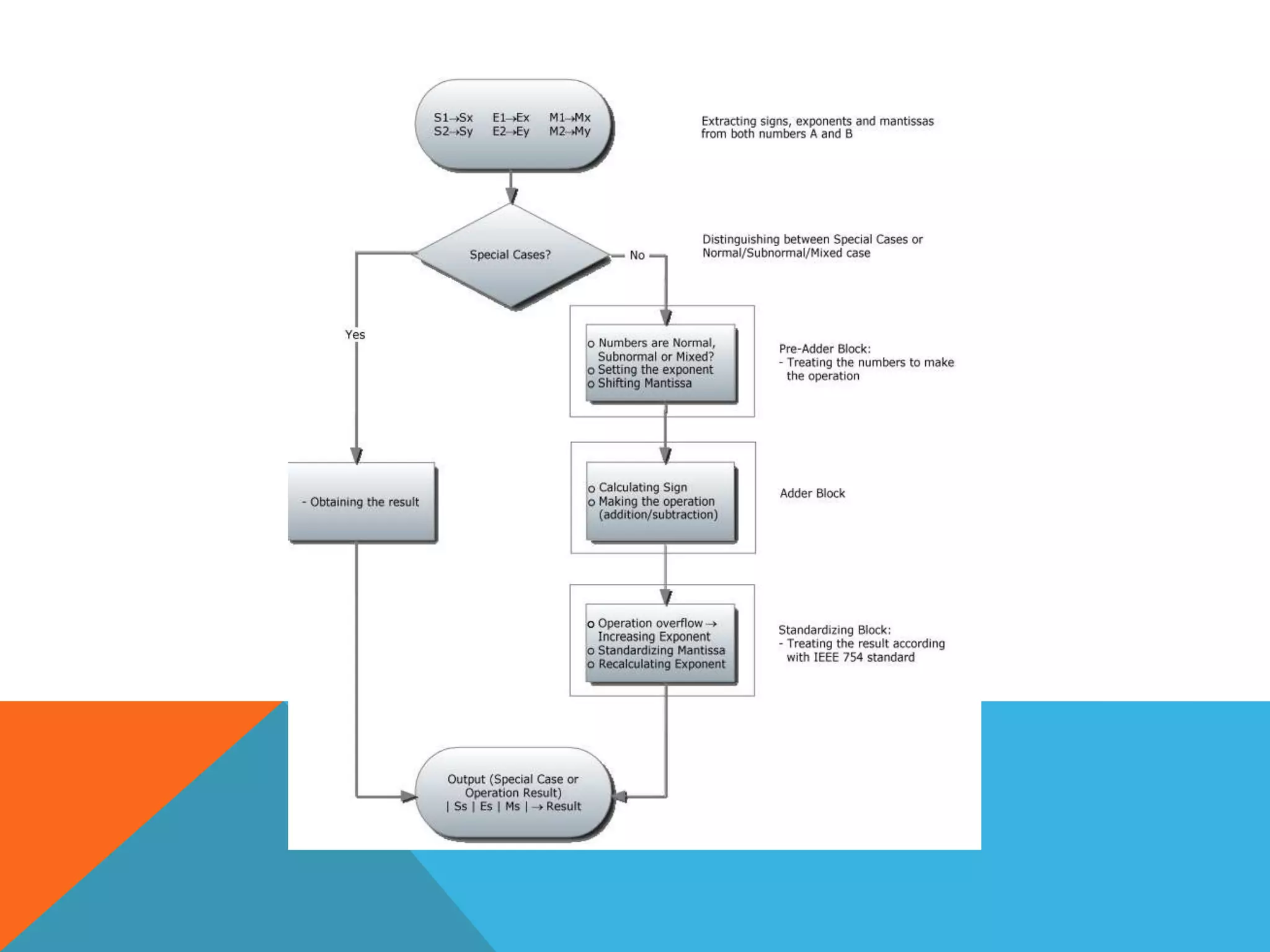

![Then the first step is finding these values.
2. Treating the special cases:
• Operations with A or B equal to zero
• Operations with ±∞
• Operations with NaN
3. Finding out what type of numbers are given:
• Normal
• Subnormal
• Mixed
4. Shifting the lower exponent number mantissa to the right [Exp1− Exp2] bits.
Setting the output exponent as the highest exponent.](https://image.slidesharecdn.com/afloating-pointadderieee754floating-point-230421085338-6a8baa1b/75/A-floating-point-adder-IEEE-754-floating-point-pptx-6-2048.jpg)