Downloaded 26 times

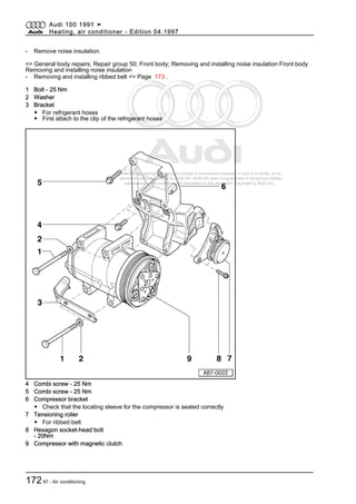
![Protected by copyright. Copying for private or commercial purposes, in part or in whole, is not
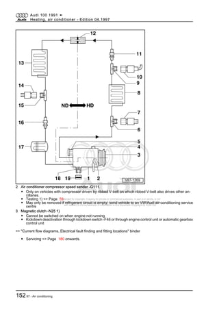
permitted unless authorised by AUDI AG. AUDI AG does not guarantee or accept any liability
with respect to the correctness of information in this document. Copyright by AUDI AG.
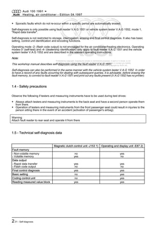
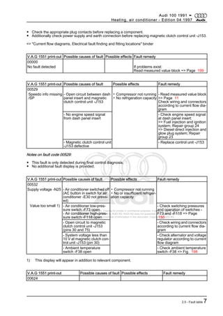
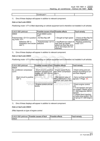
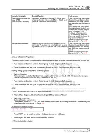
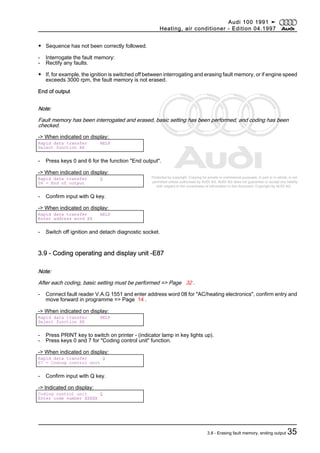
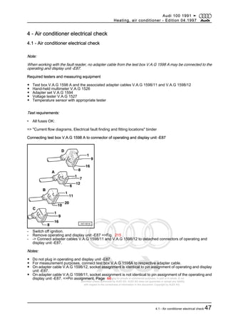
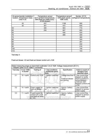
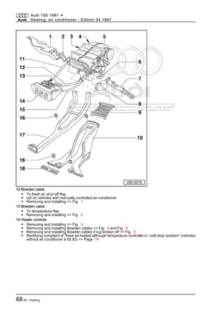
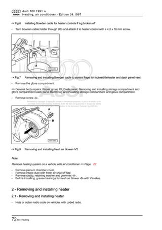
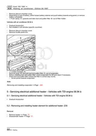
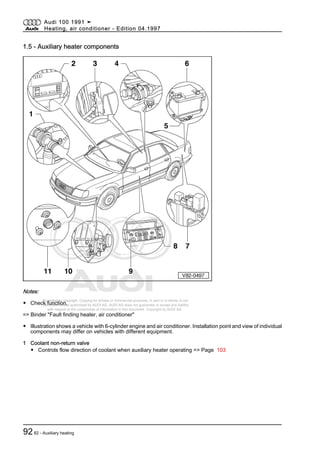
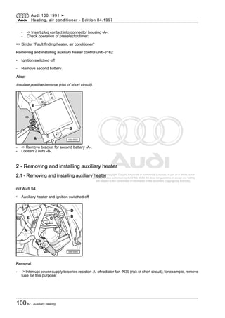
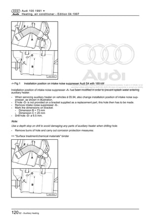
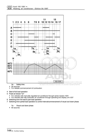
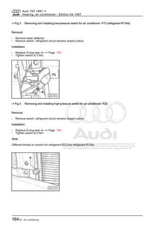
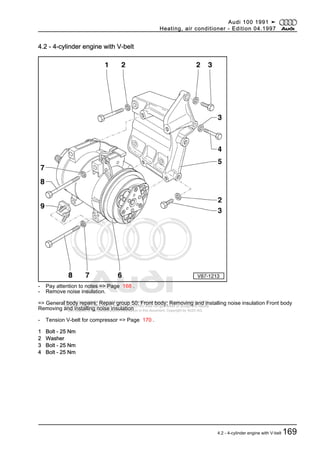
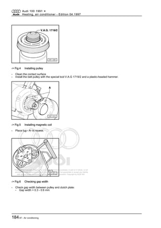
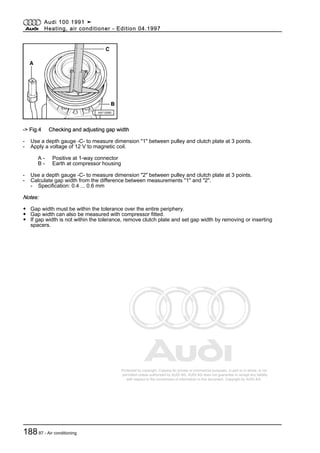
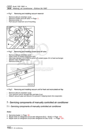
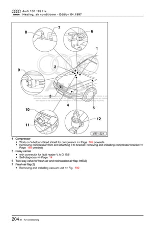
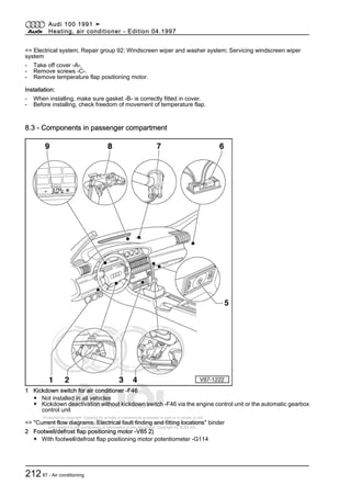
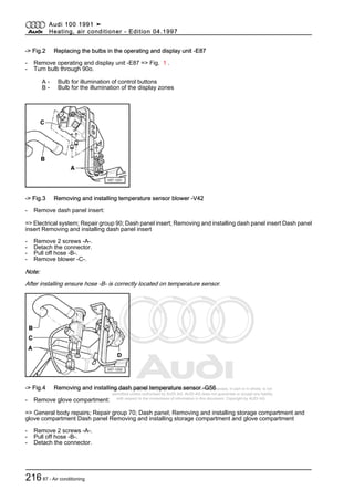
5.1 5 + 49 Air conditioner com‐
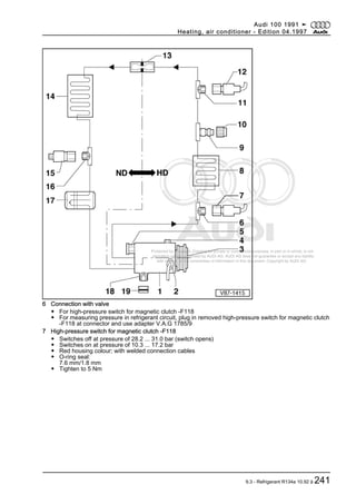
pressor speed sender
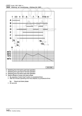
-G111
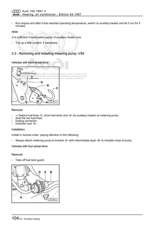
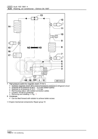
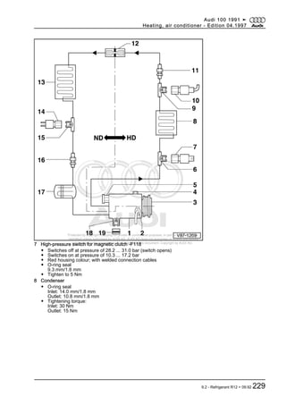
- 0.8 ... 1.5 kω - Use current flow di‐
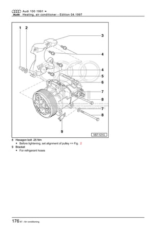
agram to eliminate
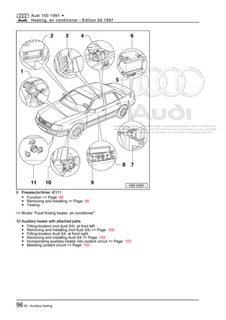
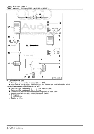
open circuit, contact
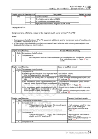
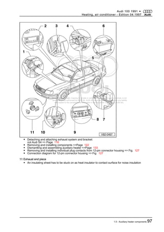
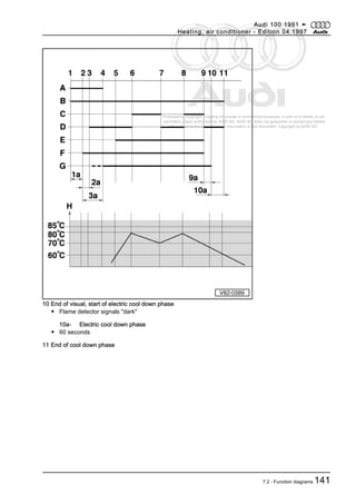
resistance or short cir‐
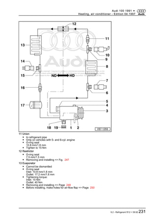
cuit
Sender -G111 defec‐
tive. Send the vehicle
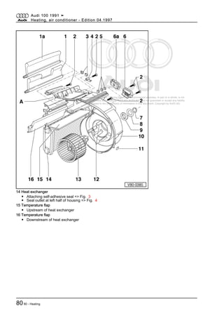
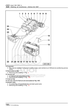
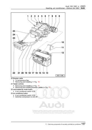
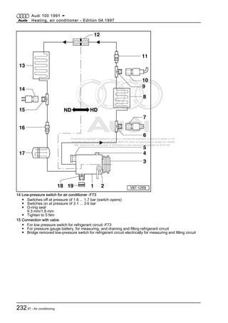
to an VW/Audi air-
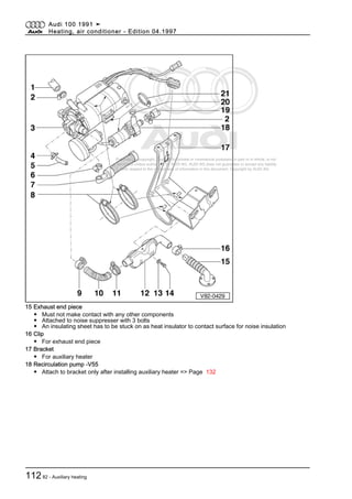
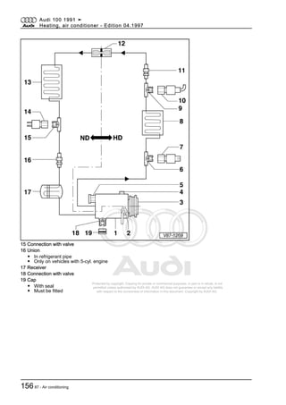
conditioning service
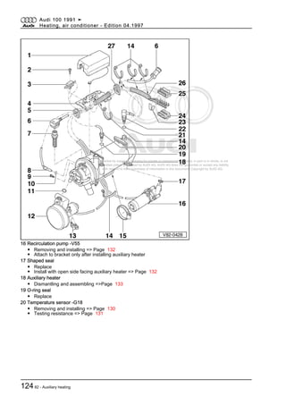
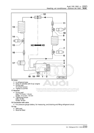
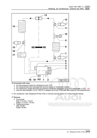
centre
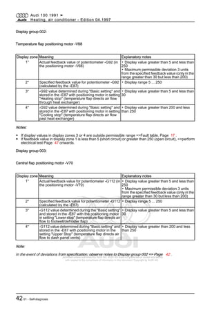
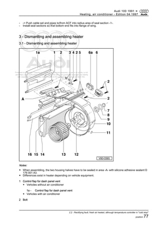
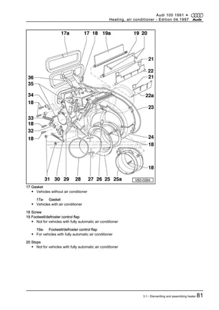
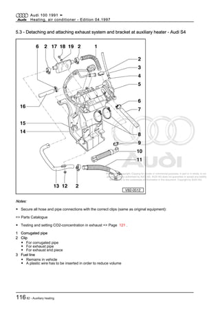
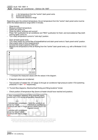
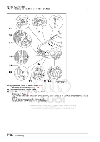
Notes:
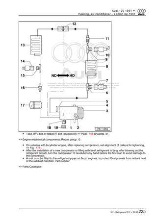
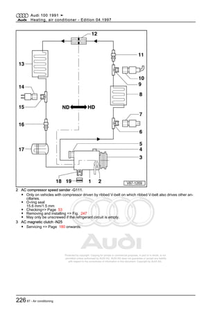
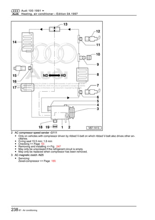
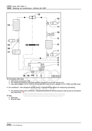
◆ Only vehicles with Zexel compressor and compressor driven by ribbed V-belt which, in addition to com‐
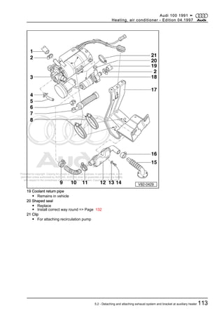
pressor also drives other ancillaries, feature an air conditioner compressor speed sender -G111.
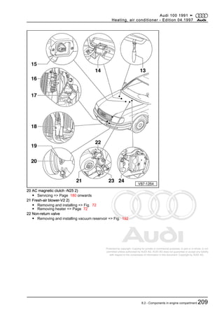
◆ Vehicles with Nippondenso compressor have no air conditioner compressor speed sender -G111.
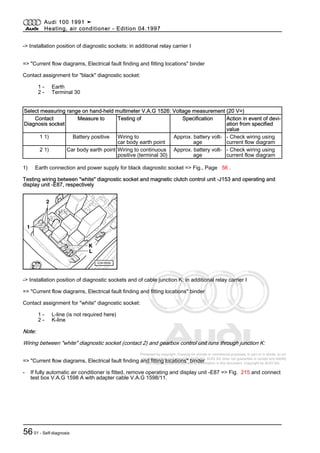
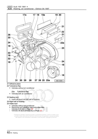
Select measuring range on hand-held multimeter V.A.G 1526: Resistance measurement (20 kω)
▪ Adapter cable V.A.G 1598/11 connected.
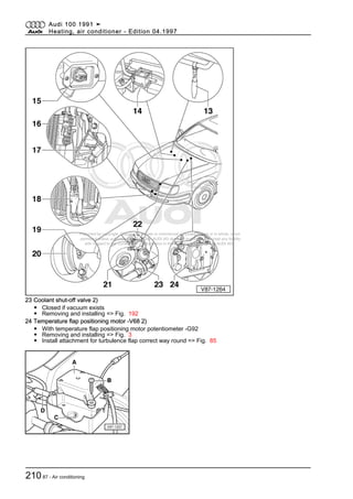
Test step V.A.G 1598
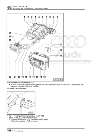
A Socket
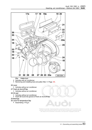
Testing of ▪ Test conditions
- Additional opera‐
tions
Specification Action in event of
deviation from
specified value
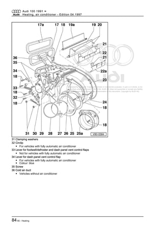
5.2 5 + earth Air conditioner com‐
pressor speed
sender
-G111
- greater than 2 kω - Rectify short circuit
according to current
flow diagram
Sender -G111 de‐
fective. Send the ve‐
hicle to an VW/Audi
air-conditioning
service centre
Select measuring range on hand-held multimeter V.A.G 1526: Voltage measurement (20 V=)
▪ Adapter cable V.A.G 1598/11 connected
5.3 5 + earth Air conditioner com‐
pressor speed
sender
-G111
▪ Engine running
▪ Compressor not
running
- Less than 1 V - Rectify short circuit
according to current
flow diagram
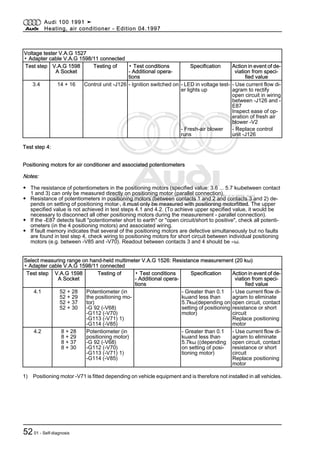
Select measuring range on hand-held multimeter V.A.G 1526: Voltage measurement (2 V font=symbol
charset=fontspecific code=64 descr='[ap]')
▪ Adapter cable V.A.G 1598/11 connected
Test step V.A.G 1598
A Socket
Testing of ▪ Test conditions
- Additional opera‐
tions
Specification Action in event of
deviation from
specified value
5.4 5 + earth Air conditioner
compressor speed
sender
-G111
▪ Magnetic clutch
relay removed
▪ Jumper between
terminals 30 and 87
at relay panel (mag‐
netic clutch engag‐
ed)
▪ Engine running
▪ Compressor run‐
ning
- greater than 0.05 V
(depends on engine
speed)
- Sender -G111 de‐
fective. Send the
vehicle to an VW/
Audi air-condition‐
ing service centre
Audi 100 1991 ➤
Heating, air conditioner - Edition 04.1997
5401 - Self-diagnosis](https://image.slidesharecdn.com/audi100heatingairconditioner-150721084450-lva1-app6891/85/Audi-100-heating-air-conditioner-60-320.jpg)
![Protected by copyright. Copying for private or commercial purposes, in part or in whole, is not
permitted unless authorised by AUDI AG. AUDI AG does not guarantee or accept any liability
with respect to the correctness of information in this document. Copyright by AUDI AG.
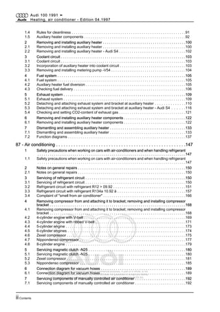
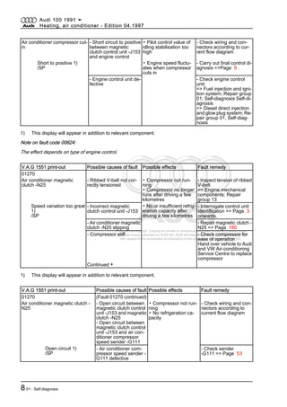
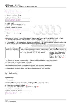
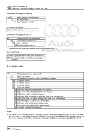
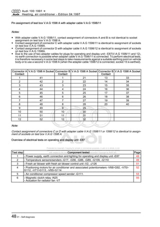
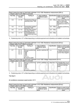
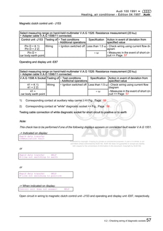
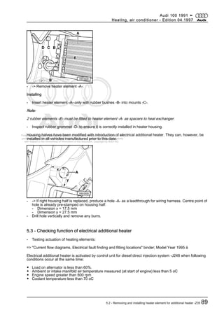
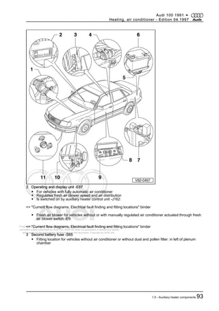
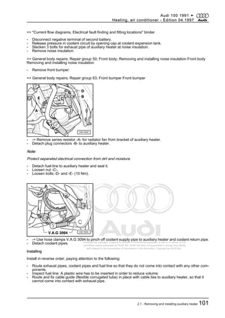
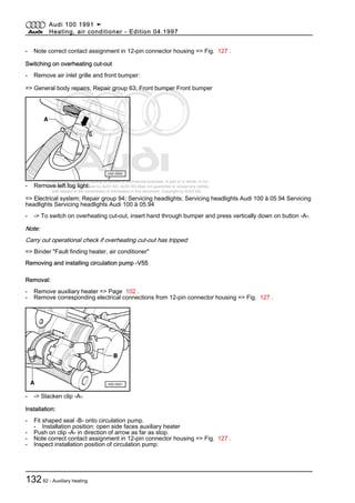
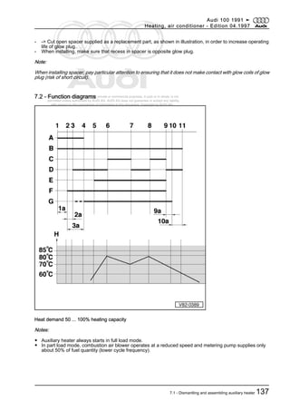
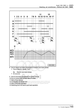
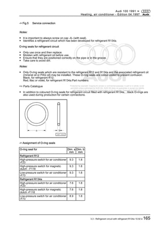
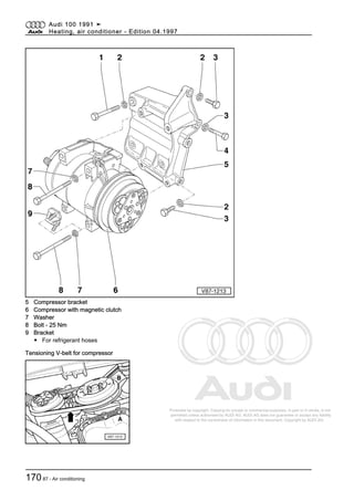
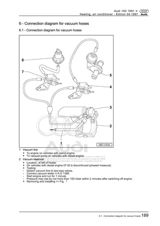
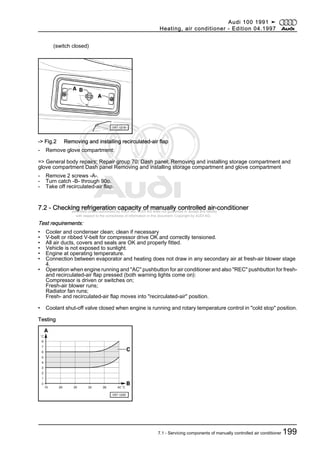
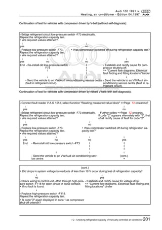
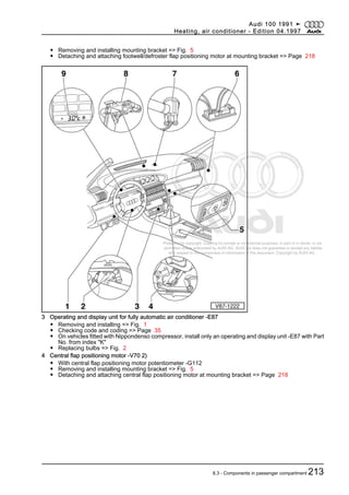
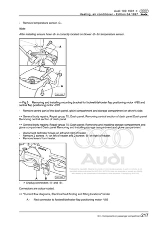
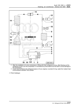
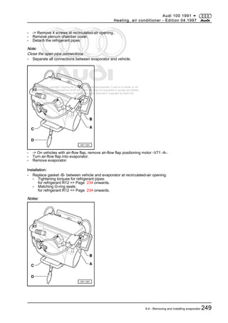
- -> Compare measured values with values in the diagram.
• If required values are not attained:
- Test actuation of radiator fan -V7 (stage 2) through air conditioner high-pressure switch -F23 (switching
pressures => item 161 respectively):
=> "Current flow diagrams, Electrical fault finding and fitting locations" binder
▪ Was compressor switched off by magnetic clutch re‐
lay -J44 during refrigeration capacity test?
↓
yes
↓
no
- Continue with test =>
Page 221 .
- Send the vehicle to an
VW/Audi air-conditioning
service centre (fault in re‐
frigerant circuit).
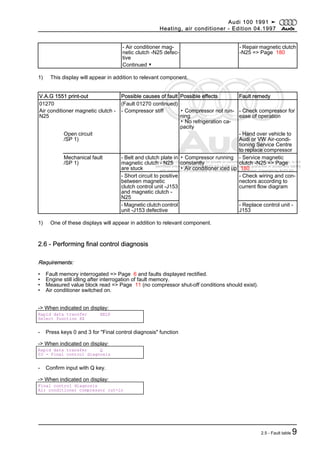
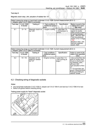
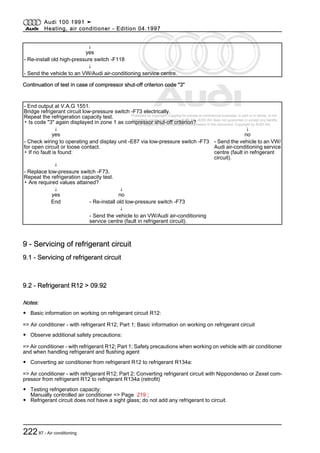
- Interrogate fault memory => Page 17 , and rectify any faults stored.
- Erase fault memory => Page 35 . Fault reader V.A.G 1551 remains connected.
- Repeat the refrigeration capacity test.
- As soon as compressor is switched off, enter address word 08 for "AC/heating electronics", confirm entry
and move forward in programme => Page 14 .
- Select the function "Read measured value block" and enter display group number 01
- Rectify cause for compressor shut-off.
▪ Does code "2" or code "3" appear in display zone 1
as compressor shut-off condition font=symbol
charset=fontspecific code=225 descr='[lang]'=>Page
39 onwards)?
↓
yes
↓
no
- Continue the test:
for code "2" =>Page 222
- Further codes => Page
39 onwards.
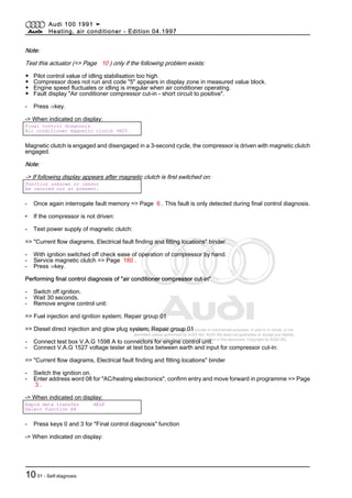
Continuation of test in case of compressor shut-off criterion code "3"
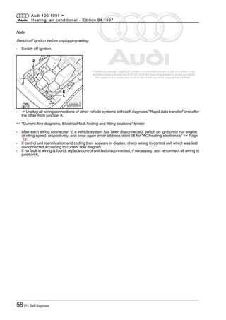
- End output at V.A.G 1551.
Check wiring between operating and display unit -E87 and high-pressure switch -F118 for open circuit or loose
contact:
=> "Current flow diagrams, Electrical fault finding and fitting locations" binder
▪ If no fault is found:
↓
- Replace high-pressure switch -F118.
Repeat the refrigeration capacity test.
▪ Is code "2" again displayed in zone 1 as compressor shut-off criterion?
Audi 100 1991 ➤
Heating, air conditioner - Edition 04.1997
8.4 - Checking refrigeration capacity of fully automatic air-conditioner 221](https://image.slidesharecdn.com/audi100heatingairconditioner-150721084450-lva1-app6891/85/Audi-100-heating-air-conditioner-227-320.jpg)

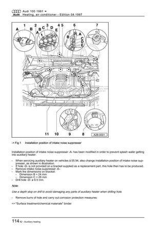
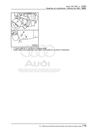
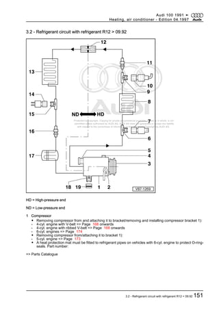
This document provides copyright information and instructions for performing self-diagnosis on the heating and air conditioning systems of Audi 100 vehicles from 1991. It includes sections on performing self-diagnosis using a fault reader on manually controlled and fully automatic air conditioning systems. Additional sections provide instructions for servicing, removing and installing heating and auxiliary heating components. The document is protected by copyright and copying is only permitted with authorization from AUDI AG.


