Download to read offline


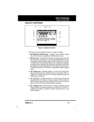
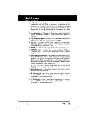
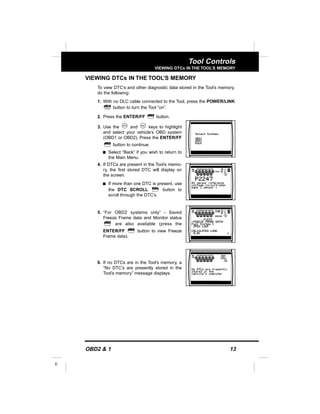


The document provides a comprehensive guide on using the OBD2 & 1 tool for troubleshooting OBD1 and OBD2 vehicles, detailing safety precautions, battery installation, and various tool functionalities. It outlines procedures for retrieving diagnostic trouble codes (DTCs) and emphasizes the significance of using the tool to diagnose vehicle issues. Additionally, the manual includes sections on vehicle-specific OBD systems covering models from Chrysler, Ford, GM, and Toyota.


![Mazda Dashboard Warning Lights: Symbols and Meanings [FULL LIST]](https://cdn.slidesharecdn.com/ss_thumbnails/mazda-warning-lights-221021085358-dcf733ba-thumbnail.jpg?width=640&height=640&fit=bounds)
![Mini Cooper Dashboard Warning Lights: Symbols and Meanings [FULL LIST]](https://cdn.slidesharecdn.com/ss_thumbnails/mini-cooper-warning-lights-221021084944-27b65ebd-thumbnail.jpg?width=640&height=640&fit=bounds)


![Toyota Dashboard Warning Lights [FULL]](https://cdn.slidesharecdn.com/ss_thumbnails/toyota-warning-lights-211126044903-thumbnail.jpg?width=640&height=640&fit=bounds)


