Downloaded 1,206 times


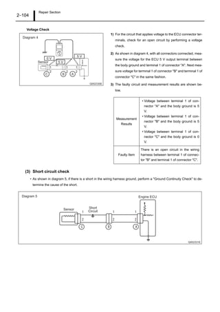
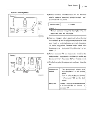
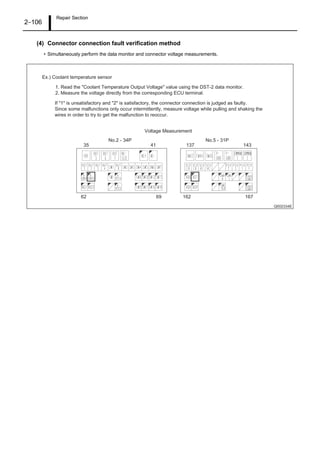
![Operation Section
1–71
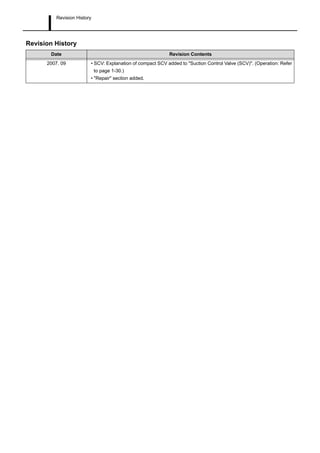
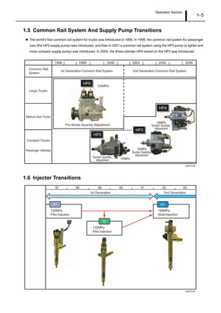
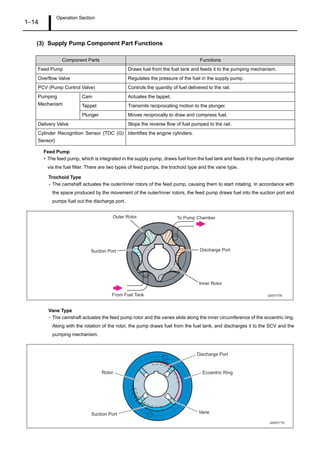
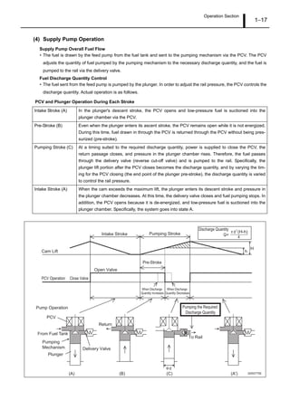
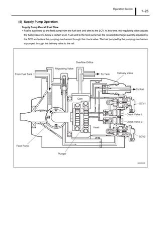
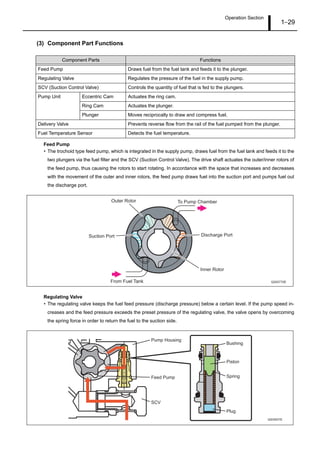
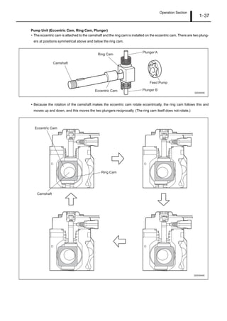
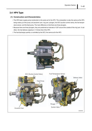
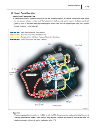
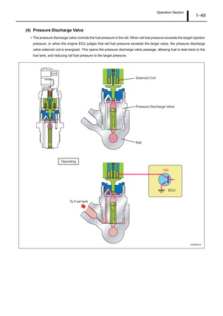
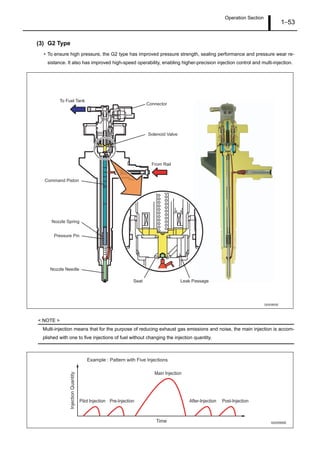
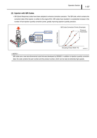
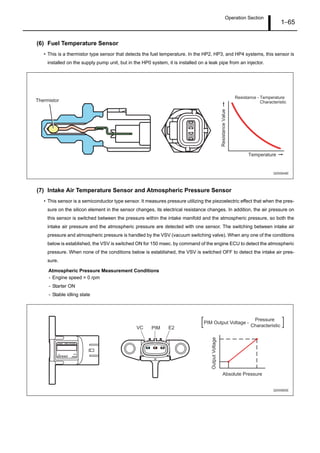
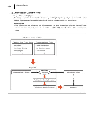
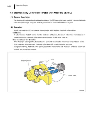
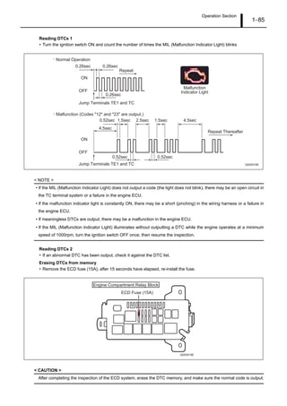
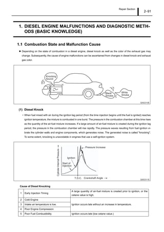
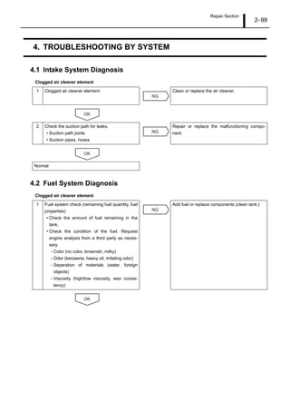
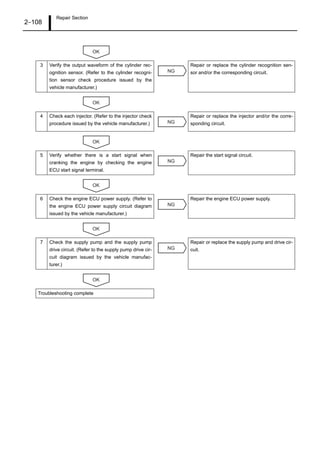
(4) Fuel Injection Rate Control
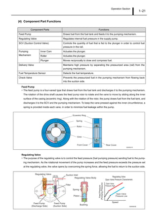
• Although the injection rate increases with the adoption of high-pressure fuel injection, the ignition lag, which is the
delay from the start of injection to the beginning of combustion, cannot be shortened to less than a certain period of
time. Therefore, the quantity of fuel injected until ignition takes place increases (the initial injection rate is too high),
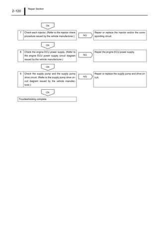
resulting in explosive combustion simultaneous with ignition, and an increase in NOx and sound. To counteract this
situation, pilot injection is provided to keep the initial injection at the minimum requirement rate, to dampen the primary
explosive combustion, and to reduce NOx and noise.
Q000895E
Injection Rate
Heat Release Rate
Large First-Stage
Combustion
Small First-Stage
Combustion
Crankshaft Angle (deg) Crankshaft Angle (deg)
-20 TDC 20 40 -20 TDC 20 40
[Ordinary Injection] [Pilot Injection]](https://image.slidesharecdn.com/densohp-3servismanual-150326060210-conversion-gate01/85/Denso-hp-3-servis-manual-76-320.jpg)
![Operation Section
1–79
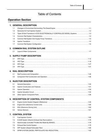
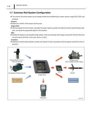
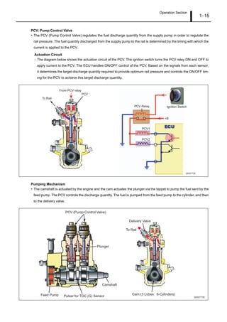
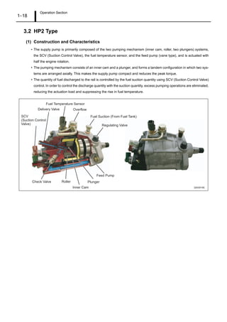
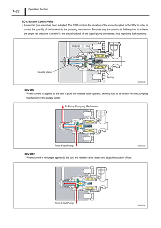
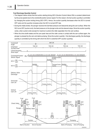
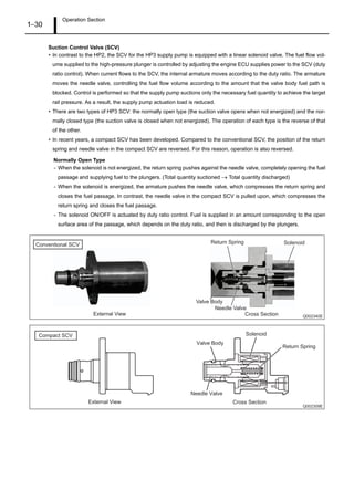
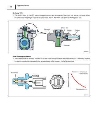
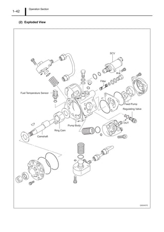
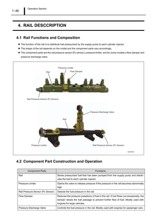
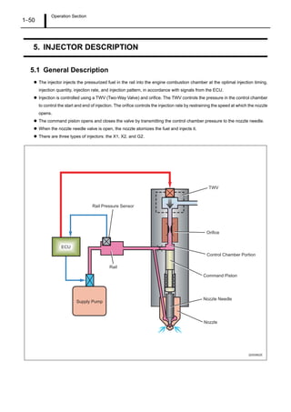
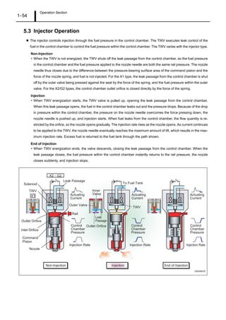
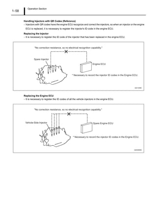
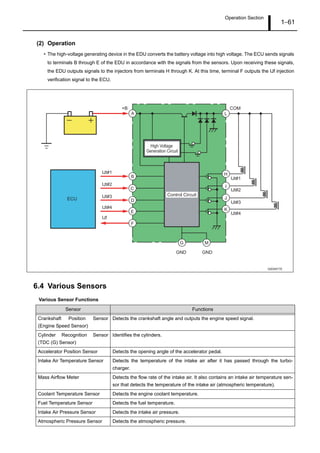
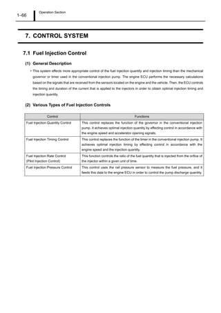
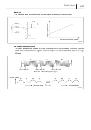
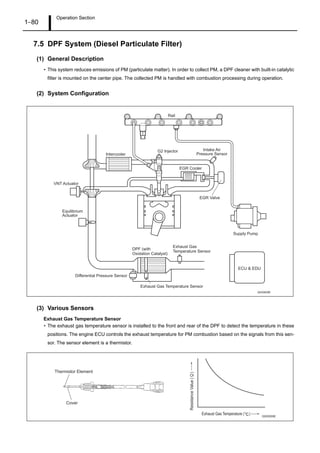
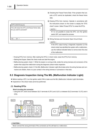
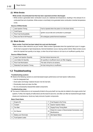
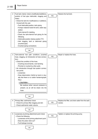
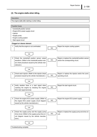
7.4 Exhaust Gas Control System
(1) General Description
• The exhaust gas control system is provided to improve warm-up and heater performance. This system actuates the
exhaust gas control valve VSV, which is attached to the exhaust manifold. It increases the exhaust pressure to in-
crease the exhaust temperature and engine load, in order to improve warm-up and heater performance.
(2) Operation
• The exhaust gas control system operates when the warm-up switch is ON, and all the conditions listed below have
been met.
Operation Conditions
- The EGR is operating.
- The coolant temperature is below 70°C.
- The ambient temperature is below 5°C.
- A minimum of 10 seconds have elapsed after starting the engine.
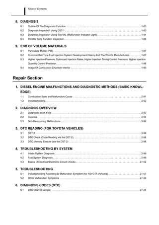
- The engine speed and fuel injection quantity are in the state shown in the graph below.
Air Cleaner
Exhaust Gas
Control Valve
Exhaust Gas
Control Valve
Vacuum Pump
VSV
Turbo Pressure
Sensor
Coolant Temperature
Sensor
EGR Valve Position
Sensor
Warm-Up Switch
Mass Airflow Meter
Cylinder
Recognition Sensor
(TDC (G) Sensor)
Accelerator
Position Sensor
Atmospheric
Pressure Sensor
ECU
Q000906E
Q000907E
WARM UP
Engine Speed
Operating Range
Extremely Low Torque
or Engine Speed Range
[Exhaust Gas Control System Operating Range]
InjectionQuantity](https://image.slidesharecdn.com/densohp-3servismanual-150326060210-conversion-gate01/85/Denso-hp-3-servis-manual-84-320.jpg)
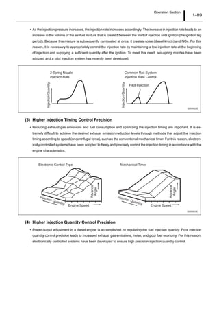


This document provides an overview of common rail diesel injection systems, including descriptions of key components and their operation. It discusses the supply pump, rail, injectors, control systems, diagnosis processes, and repair procedures. The supply pump pressurizes the fuel and supplies it to the high-pressure rail, which distributes it to the injectors. Electronic control modules precisely control fuel injection timing and quantity using inputs from sensors. Diagnostics involve checking codes, symptoms, and electrical circuits to isolate issues. Repair focuses on diagnosing specific systems or components causing malfunctions.


