Download to read offline

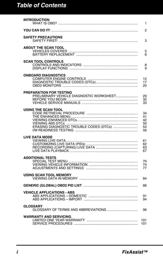


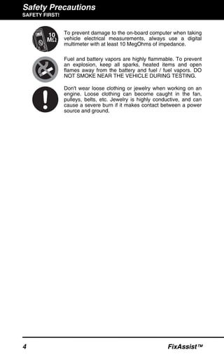


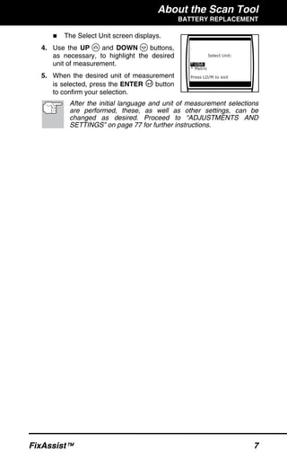


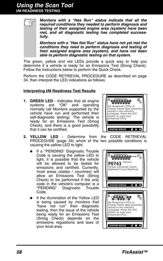


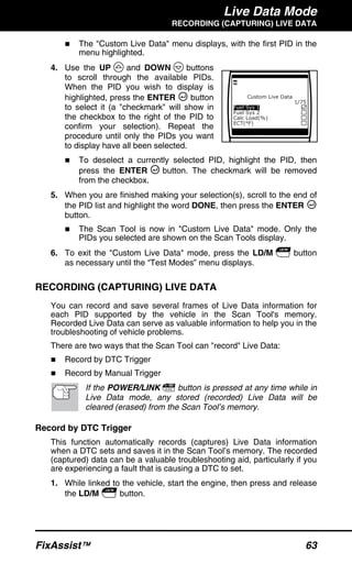


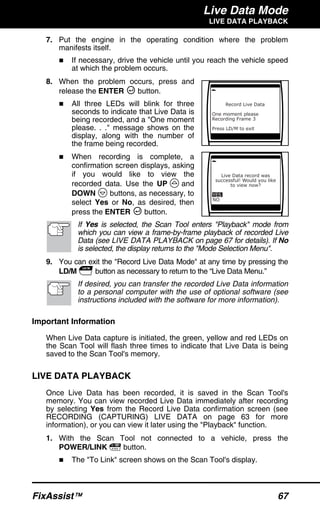


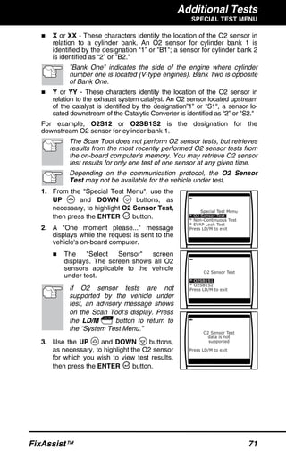


The document serves as a comprehensive manual for the FixAssist scan tool, designed to diagnose and retrieve data from OBD2 compliant vehicles, a requirement for all cars and light trucks sold in the U.S. since 1996. It covers safety precautions, operational procedures, and details about the scan tool's capabilities, including retrieving diagnostic trouble codes (DTCs) and providing repair recommendations. Additionally, it outlines specific vehicle compatibility, installation of the tool, and features for viewing live and historical data related to vehicle diagnostics.


![Toyota Dashboard Warning Lights [FULL]](https://cdn.slidesharecdn.com/ss_thumbnails/toyota-warning-lights-211126044903-thumbnail.jpg?width=640&height=640&fit=bounds)

![Mini Cooper Dashboard Warning Lights: Symbols and Meanings [FULL LIST]](https://cdn.slidesharecdn.com/ss_thumbnails/mini-cooper-warning-lights-221021084944-27b65ebd-thumbnail.jpg?width=640&height=640&fit=bounds)

![Mazda Dashboard Warning Lights: Symbols and Meanings [FULL LIST]](https://cdn.slidesharecdn.com/ss_thumbnails/mazda-warning-lights-221021085358-dcf733ba-thumbnail.jpg?width=640&height=640&fit=bounds)