SlideShare a Scribd company logo
1 of 8
Download to read offline
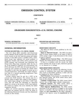
XJ                                                                                      EMISSION CONTROL SYSTEM                      25 - 1


                                   EMISSION CONTROL SYSTEM
                                                             CONTENTS

                                                              page                                                                    page

EXHAUST EMISSION CONTROLS—2.5L DIESEL                                   ON-BOARD DIAGNOSTICS—2.5L DIESEL
 ENGINE . . . . . . . . . . . . . . . . . . . . . . . . . . . . . . 5    ENGINE . . . . . . . . . . . . . . . . . . . . . . . . . . . . . . 1


                    ON-BOARD DIAGNOSTICS—2.5L DIESEL ENGINE

                                                                   INDEX
                                                              page                                                                    page

GENERAL INFORMATION                                                     DESCRIPTION AND OPERATION
 SYSTEM DESCRIPTION—2.5L DIESEL ENGINE                                   DIAGNOSTIC TROUBLE CODES . . . . . . . . . . . . 2
 ....................................... 1

GENERAL INFORMATION                                                     MONITORED CIRCUITS
                                                                           The MSA can detect certain problems in the elec-
SYSTEM DESCRIPTION—2.5L DIESEL ENGINE                                   trical system.
  The 2.5L diesel MSA controller and Powertrain                            Open or Shorted Circuit – The MSA can deter-
Control Module (PCM) monitor and control many dif-                      mine if sensor output (which is the input to MSA is
ferent circuits in the fuel injection pump and engine                   within proper range. It also determines if the circuit
systems. If the MSA senses a problem with a moni-                       is open or shorted.
tored circuit that indicates an actual problem, a                          Output Device Current Flow – The MSA senses
Diagnostic Trouble Code (DTC) will be stored in the                     whether the output devices are electrically connected.
PCM’s memory, and eventually may illuminate the                            If there is a problem with the circuit, the MSA
Diesel Glow Plug lamp constantly while the key is                       senses whether the circuit is open, shorted to ground
on. If the problem is repaired, or is intermittent, the                 (–), or shorted to (+) voltage.
PCM will erase the DTC after 40 warm-up cycles. A
warm-up cycle consists of starting the vehicle when                     NON–MONITORED CIRCUITS
the engine is cold, then the engine to warms up to a                      The MSA does not monitor the following circuits,
certain temperature, and finally, the engine tempera-                   systems or conditions that could have malfunctions
ture falls to a normal operating temperature, then                      that result in driveability problems. A DTC will not
the key is turned off.                                                  be displayed for these conditions.
  Certain criteria must be met for a DTC to be                            Fuel Pressure: Fuel pressure is controlled by the
entered into PCM memory. The criteria may be a                          fuel injection pump. The PCM cannot detect prob-
specific range of engine rpm, engine or fuel tempera-                   lems in this component.
ture and/or input voltage to the PCM. A DTC indi-                         Cylinder Compression: The MSA cannot detect
cates that the PCM has identified an abnormal                           uneven, low, or high engine cylinder compression.
signal in a circuit or the system. A DTC may indicate                     Exhaust System: The MSA cannot detect a
the result of a failure, but never identify the failed                  plugged, restricted or leaking exhaust system.
component directly.                                                       Fuel Injector Malfunctions: The MSA cannot
  There are several operating conditions that the                       determine if the fuel injector is clogged, or the wrong
MSA does not monitor and set a DTC for. Refer to                        injector is installed. The fuel injectors on the diesel
the following Monitored Circuits and Non–Monitored                      engine are not controlled by the MSA, although a
Circuits in this section.                                               defective fuel injector sensor is monitored by the
                                                                        PCM.
25 - 2   EMISSION CONTROL SYSTEM                                                                        XJ
GENERAL INFORMATION (Continued)
  Vacuum Assist: Leaks or restrictions in the vac-     DESCRIPTION AND OPERATION
uum circuits of vacuum assisted engine control sys-
tem devices are not monitored by the MSA.              DIAGNOSTIC TROUBLE CODES
  MSA System Ground: The MSA cannot deter-               On the following pages, a list of DTC’s is provided
mine a poor system ground. However, a DTC may be       for the 2.5L diesel engine. A DTC indicates that the
generated as a result of this condition.               PCM has recognized an abnormal signal in a circuit
  MSA/PCM Connector Engagement: The MSA                or the system. A DTC may indicate the result of a
cannot determine spread or damaged connector pins.     failure, but most likely will not identify the failed
However, a DTC may be generated as a result of this    component directly.
condition.
                                                       ACCESSING DIAGNOSTIC TROUBLE CODES
HIGH AND LOW LIMITS                                      A stored DTC can be displayed through the use of
  The MSA compares input signal voltages from each     the DRB III scan tool. The DRB III connects to the
input device. It will establish high and low limits    data link connector. The data link connector is
that are programmed into it for that device. If the    located under the instrument panel near bottom of
input voltage is not within specifications and other   the steering column (Fig. 1).
DTC criteria are met, a DTC will be stored in mem-
ory. Other DTC criteria might include engine rpm
limits or input voltages from other sensors or
switches. The other inputs might have to be sensed
by the MSA when it senses a high or low input volt-
age from the control system device in question.


                                                          Fig. 1 Data Link Connector Location—Typical
                                                       ERASING TROUBLE CODES
                                                         After the problem has been repaired, use the DRB
                                                       III scan tool to erase a DTC.
XJ                                                            EMISSION CONTROL SYSTEM         25 - 3
DESCRIPTION AND OPERATION (Continued)
MSA CONTROLLER DRBIII CODES

Generic Scan Tool Code   DRB III Scan Tool Display
P0100                    Mass of Volumes of Air Flow Plausibility
                         Mass of Volumes of Air Flow Signal High Exceeded
                         Mass of Volumes of Air Flow Signal Low Exceeded
P0115                    Temperature of Engine Coolant SRC High Exceeded
                         Temperature of Engine Coolant SRC Low Exceeded
P0180                    Fuel Temperature Sensor SRC High Exceeded
                         Fuel Temperature Sensor SRC Low Exceeded
P0400                    EGR Open Circuit
                         EGR Short Circuit
P0500                    Vehicle Speed Sensor PEC Frequency Too High
                         Vehicle Speed Sensor Signal High Exceeded
                         Vehcle Speed Sensor Plausibility
P0725                    Engine Speed Sensor Dynamic Plausibility
                         Engine Speed Sensor Over Speed Recognition
                         Engine Speed Sensor Static Plausibilty
P1105                    Atmospheric Pressure Sensor SRC High Exceeded
                         Atmospheric Pressure Sensor SRC Low Exceeded
P1201                    Needle Movement Sensor High Exceeded
                         Needle Movement Sensor Low Exceeded
P1220                    Fuel   Quantity Actuator   Neg. Gov. Deviation Cold
                         Fuel   Quantity Actuator   Neg. Gov. Deviation Warm
                         Fuel   Quantity Actuator   Pos. Gov. Deviation Cold
                         Fuel   Quantity Actuator   Pos. Gov. Deviation Warm
P1225                    Control Sleeve Sensor Signal High Exceeded
                         Control Sleeve Sensor Start End Pos. Not Attained
                         Control Sleeve Sensor Stop End Pos. Not Attained
P1230                    Timing Control Negative Governing Governor Deviation
                         Timing Control Positive Governing Governor Deviation
P1515                    Accelerator   Pedal   Postion Sensor Signal High Exceeded
                         Accelerator   Pedal   Sensor Signal Low Exceeded
                         Accelerator   Pedal   Sensor Signal PWG Plaus With Low Idle Switch
                         Accelerator   Pedal   Sensor Signal PWG Plaus With Potentiometer
P1600                    Battery Voltage SRC High Exceeded
P1605                    Terminal #15 Plausibility After Startup
P1610                    Regulator Lower Regulator Limit
                         Regulator Upper Regulator Limit
P1615                    Microcontroller Gate-Array Monitoring
                         Microcontroller Gate-Array Watchdog
                         Microcontroller Prepare Fuel Quantity Stop
                         Microcontroller Recovery Was Occurred
                         Microcontrller Redundant Overrun Monitoring
P1630                    Solenoid Valve Controller Open Circuit
                         Solenoid Valve Controller Short Circuit
25 - 4   EMISSION CONTROL SYSTEM                                                       XJ
DESCRIPTION AND OPERATION (Continued)

Generic Scan Tool Code       DRB III Scan Tool Display
P1635                        Glow Relay Controller Open Circuit
                             Glow Relay Controller Short Circuit
P1650                        Diagnostic Lamp Open Circuit
                             Diagnostic Lamp Short Circuit
P1660                        Redundant Emer. Stop Plausibility In After-Run
                             Redundant Emer Stop Powerstage Defective
P1665                        Cruise Status Indicator Lamp Short Circuit
P1680                        EEPROM     Plausibility   Checksum Error for Adj.
                             EEPROM     Plausibility   Checksum Error in CC212
                             EEPROM     Plausibility   Communication With EEPROM
                             EEPROM     Plausibility   Func. Switch Wrong or Missing
                             EEPROM     Plausibility   Ver Number Not Corresponding
P1685                        Vehicle Theft Alarm Code Line Breakdown
P1703                        Brake Signal Plaus With Redundant Contact
P1740                        Clutch Signal Plausibilty
P1725                        Inductive Aux. Speed Sensor Dynamic Plausibilty
                             Inductive Aux. Speed Sensor Overspeed Recognition
                             Inductive Aux Speed Sensor Plausibilty
                             Inductive Aux. Speed Sensor Static Plausibilty


PCM DRBIII CODES


Generic Scan Tool Code       DRBIII Scan Tool Display
P0117                        Engine Coolant Volts Lo
P0118                        Engine Coolant Volts Hi
P0500                        Vehicle Speed Signal
P0601                        Internal Self Test
P1296                        5 VDC Output
P1391                        Loss of Cam or Crank
XJ                                                                                      EMISSION CONTROL SYSTEM                       25 - 5


              EXHAUST EMISSION CONTROLS—2.5L DIESEL ENGINE

                                                                   INDEX
                                                                 page                                                                  page

DESCRIPTION AND OPERATION                                               REMOVAL AND INSTALLATION
  EXHAUST GAS RECIRCULATION (EGR)                                        EGR TUBE . . . . . . . . . . . . . . . . . . . . . . . .   ..... 7
   SYSTEM . . . . . . . . . . . . . . . . . . . . . . . .     ..... 5    EGR VALVE . . . . . . . . . . . . . . . . . . . . . . .    ..... 7
  VACUUM HOSE ROUTING SCHEMATIC .                             ..... 5    ELECTRIC VACUUM MODULATOR (EVM)                            ..... 7
DIAGNOSIS AND TESTING                                                   SPECIFICATIONS
  EGR GAS FLOW TEST . . . . . . . . . . . . . .               ..... 6    TORQUE CHART—2.5L DIESEL . . . . . . .                     ..... 8
  ELECTRIC VACUUM MODULATOR (EVM)
   TEST . . . . . . . . . . . . . . . . . . . . . . . . . .   ..... 7

DESCRIPTION AND OPERATION                                               EXHAUST GAS RECIRCULATION (EGR) SYSTEM
VACUUM HOSE ROUTING SCHEMATIC                                           GENERAL INFORMATION
   Vacuum for the EGR system is supplied by the                           The EGR system reduces oxides of nitrogen (NOx)
internal engine mounted vacuum pump. Refer to                           in the engine exhaust. This is accomplished by allow-
EGR System Operation for vacuum pump informa-                           ing a predetermined amount of hot exhaust gas to
tion. Vacuum harness routing for emission related                       recirculate and dilute the incoming fuel/air mixture.
components is displayed in (Fig. 1).                                      A malfunctioning EGR system can cause engine
                                                                        stumble, sags or hesitation, rough idle, engine stall-
                                                                        ing and poor driveability.

                                                                        EGR SYSTEM OPERATION
                                                                          The system consists of:
                                                                          • An EGR valve assembly. The valve is located
                                                                        behind the intake manifold (Fig. 2).


                Fig. 1 Typical Hose Routing


                                                                                  Fig. 2 EGR Valve and Tube Location
25 - 6   EMISSION CONTROL SYSTEM                                                                          XJ
DESCRIPTION AND OPERATION (Continued)
   • An Electric Vacuum Modulator (EVM). The EVM          The EGR system will be shut down by the MSA
is sometimes referred to as the EGR control solenoid    after 60 seconds of continuous engine idling to
or EGR duty cycle solenoid. The EVM serves two dif-     improve idle quality.
ferent functions. One is to control vacuum bleed–off
of the EGR valve. The other is to control the “on
time” of the EGR valve.                                 DIAGNOSIS AND TESTING
   • The MSA operates the EVM. The MSA is located
is located inside the vehicle in the center consule.    EGR GAS FLOW TEST
   • An EGR tube (Fig. 2) connecting a passage in          Use the following test procedure to determine if
the EGR valve to the rear of the exhaust manifold.      exhaust gas is flowing through the EGR valve. It can
   • The vacuum pump supplies vacuum for the            also be used to determine if the EGR tube is plugged,
EVM and the EGR valve. This pump also supplies          or the system passages in the intake or exhaust man-
vacuum for operation of the power brake booster. The    ifolds are plugged.
pump is located internally in the front of the engine      This is not to be used as a complete test of the
block (Fig. 3) and is driven by the crankshaft gear.    EGR system.
                                                           The engine must be started, running and warmed
                                                        to operating temperature for this test.
                                                           (1) All EGR valves are equipped with a vacuum
                                                        supply fitting located on the EGR valve vacuum
                                                        motor (Fig. 2).
                                                           (2) Disconnect the rubber hose from the vacuum
                                                        supply fitting (Fig. 2).
                                                           (3) Connect a hand–held vacuum pump to this fit-
                                                        ting.
                                                           (4) Start the engine.
                                                           (5) Slowly apply 10 inches of vacuum to the fitting
                                                        on the EGR valve motor. Vacuum should hold steady
                                                        at 10 inches. If not, replace the EGR valve. If vac-
                                                        uum holds steady at 10 inches, proceed to next step.
                                                           (6) While applying vacuum, and with the engine
                                                        running at idle speed, the idle speed should drop, a
                                                        rough idle may occur, or the engine may even stall.
           Fig. 3 Internal Vacuum Pump                  This is indicating that exhaust gas is flowing through
   • Vacuum lines and hoses to connect the various      the EGR tube between the intake and exhaust man-
components.                                             ifolds.
   When the MSA supplies a variable ground signal          (7) If the engine speed did not change, the EGR
to the EVM, EGR system operation starts to occur.       valve may be defective, the EGR tube may be
The MSA will monitor and determine when to supply       plugged with carbon, or the passages in the intake
and remove this variable ground signal. This will       and exhaust manifolds may be plugged with carbon.
depend on inputs from the engine coolant tempera-             (a) Remove EGR valve from engine. Refer to
ture, throttle position and engine speed sensors.          EGR Valve Removal in this group.
   When the variable ground signal is supplied to the         (b) Apply vacuum to the vacuum motor fitting
EVM, vacuum from the vacuum pump will be                   and observe the stem on the EGR valve. If the
allowed to pass through the EVM and on to the EGR          stem is moving, it can be assumed that the EGR
valve with a connecting hose.                              valve is functioning correctly. The problem is in
   Exhaust gas recirculation will begin in this order      either a plugged EGR tube or plugged passages at
when:                                                      the intake or exhaust manifolds. Refer to step (c).
   • The MSA determines that EGR system operation          If the stem will not move, replace the EGR valve.
is necessary.                                                 (c) Remove the EGR tube between the intake
   • The engine is running to operate the vacuum           and exhaust manifolds. Check and clean the EGR
pump.                                                      tube and its related openings on the manifolds.
   • A variable ground signal is supplied to the EVM.      Refer to EGR Tube in this group for procedures.
   • Variable vacuum passes through the EVM to the         Do not attempt to clean the EGR valve. If the
EGR valve.                                              valve shows evidence of heavy carbon build–up near
   • The inlet seat (poppet valve) at the bottom of     the base, replace it.
the EGR valve opens to dilute and recirculate
exhaust gas back into the intake manifold.
XJ                                                                    EMISSION CONTROL SYSTEM           25 - 7
DIAGNOSIS AND TESTING (Continued)
ELECTRIC VACUUM MODULATOR (EVM) TEST                        (3) Loosen fitting at exhaust manifold end of tube
                                                         (Fig. 2).
VACUUM TEST                                                 (4) Remove EGR tube and discard old gasket.
  With the engine running, disconnect the vacuum            (5) Clean gasket mating surfaces and EGR tube
supply line at the fitting on the EVM. Minimum vac-      flange gasket surfaces.
uum should be no less than 20 inches. If vacuum is          (6) Check for signs of leakage or cracked surfaces
lower, check for leaks in vacuum supply line. If leaks   at both ends of tube, exhaust manifold and EGR
cannot be found, check for low vacuum at vacuum          valve.
pump. Refer to Group 5, Brake System for proce-
dures.                                                   INSTALLATION
                                                           (1) Install a new gasket to EGR valve end of EGR
                                                         tube.
REMOVAL AND INSTALLATION                                   (2) Position EGR tube to engine.
                                                           (3) Loosely tighten fitting at exhaust manifold end
EGR VALVE                                                of tube.
                                                           (4) Install 2 mounting bolts at EGR valve end of
REMOVAL                                                  tube. Tighten bolts to 23 N·m (204 in. lbs.) torque.
  (1) Remove the rubber hose from turbocharger to          (5) Tighten fitting at exhaust manifold end of tube.
metal tube.                                                (6) Install hose from turbocharger to metal tube.
  (2) Disconnect vacuum line at EGR valve vacuum
supply fitting (Fig. 2).                                 ELECTRIC VACUUM MODULATOR (EVM)
  (3) Loosen the tube fitting at exhaust manifold end     The EVM (EGR Duty Cycle Purge Solenoid) is
of EGR tube (Fig. 2).                                    mounted to the side of the PDC.
  (4) Remove the two bolts retaining the EGR tube
to the side of EGR valve (Fig. 2).                       REMOVAL
  (5) Remove the two EGR valve mounting bolts              (1) Disconnect both cables from battery, negative
(Fig. 2) and remove EGR valve.                           cable first.
  (6) Discard both of the old EGR mounting gaskets.        (2) Remove 2 screws holding PDC to bracket,
                                                         swing out of way.
INSTALLATION                                               (3) Remove nut and clamp holding battery to bat-
   (1) Clean the intake manifold of any old gasket       tery tray (Fig. 4).
material.
   (2) Clean the end of EGR tube of any old gasket
material.
   (3) Position the EGR valve and new gasket to the
intake manifold.
   (4) Install two EGR valve mounting bolts. Do not
tighten bolts at this time.
   (5) Position new gasket between EGR valve and
EGR tube.
   (6) Install two EGR tube bolts. Tighten all four
mounting bolts to 23 N·m (204 in. lbs.).
   (7) Tighten EGR tube fitting at exhaust manifold.
   (8) Connect vacuum line to EGR valve.
   (9) Install the rubber hose from turbocharger to
metal tube.

EGR TUBE
  The EGR tube connects the EGR valve to the rear
of the exhaust manifold (Fig. 2).

REMOVAL
  (1) Remove rubber hose from turbocharger to
metal tube.
  (2) Remove two EGR tube mounting bolts at EGR                          Fig. 4 Battery Clamp
valve end of tube (Fig. 2).
                                                           (4) Remove battery from vehicle.
                                                           (5) Disconnect two vacuum hoses at EVM.
25 - 8   EMISSION CONTROL SYSTEM                                                                             XJ
REMOVAL AND INSTALLATION (Continued)
  (6) Remove mounting screws of EVM.                SPECIFICATIONS
  (7) Remove the EVM to gain access to the EVM
electrical connector.                               TORQUE CHART—2.5L DIESEL
  (8) Remove electrical connector at EVM.
                                                    Description                                         Torque
INSTALLATION
  (1) Install electrical connector to EVM.          EGR Valve Mounting Bolts . . . 23 N·m (204 in. lbs.)
  (2) Install EVM and tighten mounting screws.      EGR Tube Mounting Bolts . . . . 23 N·m (204 in. lbs.)
  (3) Connect vacuum hoses.                         EVM (Electric Vacuum Modulator)
  (4) Install PDC to bracket and tighten mounting     Mounting Bolt . . . . . . . . . . . . . 2 N·m (20 in. lbs.)
screws.
  (5) Install battery.
  (6) Connect battery cables positive first.

More Related Content

What's hot

Perkins 1600 series industrial engine ( xgh) service repair manual
Perkins 1600 series industrial engine ( xgh) service repair manualPerkins 1600 series industrial engine ( xgh) service repair manual
Perkins 1600 series industrial engine ( xgh) service repair manualfjjksekksemm
 
Perkins 1600 series industrial engine ( xgd ) service repair manual
Perkins 1600 series industrial engine ( xgd ) service repair manualPerkins 1600 series industrial engine ( xgd ) service repair manual
Perkins 1600 series industrial engine ( xgd ) service repair manualfjsefksemmm
 
Perkins 1600 series industrial engine (xga ) service repair manual
Perkins 1600 series industrial engine (xga ) service repair manualPerkins 1600 series industrial engine (xga ) service repair manual
Perkins 1600 series industrial engine (xga ) service repair manualfjskekxswesemm
 
Perkins 1600 series industrial engine (xgh) service repair manual
Perkins 1600 series industrial engine (xgh) service repair manualPerkins 1600 series industrial engine (xgh) service repair manual
Perkins 1600 series industrial engine (xgh) service repair manualfjskkmemem
 
Perkins 1600 series industrial engine (xgb ) service repair manual
Perkins 1600 series industrial engine (xgb ) service repair manualPerkins 1600 series industrial engine (xgb ) service repair manual
Perkins 1600 series industrial engine (xgb ) service repair manualfjjksekksemm
 
PERKINS 1600 SERIES INDUSTRIAL ENGINE ( XGE ) Service Repair Manual
PERKINS 1600 SERIES INDUSTRIAL ENGINE ( XGE ) Service Repair ManualPERKINS 1600 SERIES INDUSTRIAL ENGINE ( XGE ) Service Repair Manual
PERKINS 1600 SERIES INDUSTRIAL ENGINE ( XGE ) Service Repair Manualfudjfjsjekkemm
 
Perkins 1600 series industrial engine (xgf) service repair manual
Perkins 1600 series industrial engine (xgf) service repair manualPerkins 1600 series industrial engine (xgf) service repair manual
Perkins 1600 series industrial engine (xgf) service repair manualfjjskeknjufksemm
 
Cat industrial engines brochure
Cat industrial engines brochureCat industrial engines brochure
Cat industrial engines brochuremartinedigiovanni
 
Electronic modular control panel ii + paralleling emcp ii + p systems ope...
Electronic modular control panel ii + paralleling   emcp ii + p   systems ope...Electronic modular control panel ii + paralleling   emcp ii + p   systems ope...
Electronic modular control panel ii + paralleling emcp ii + p systems ope...Otorongosabroso
 
PERKINS 1106C-E70TA AND 1106D-E70TA INDUSTRIAL ENGINE (Model PV)Service Repai...
PERKINS 1106C-E70TA AND 1106D-E70TA INDUSTRIAL ENGINE (Model PV)Service Repai...PERKINS 1106C-E70TA AND 1106D-E70TA INDUSTRIAL ENGINE (Model PV)Service Repai...
PERKINS 1106C-E70TA AND 1106D-E70TA INDUSTRIAL ENGINE (Model PV)Service Repai...jknmms ekdms
 
PERKINS 1100 SERIES 1106C INDUSTRIAL ENGINE (ELECTRONIC)(Model VK)Service Rep...
PERKINS 1100 SERIES 1106C INDUSTRIAL ENGINE (ELECTRONIC)(Model VK)Service Rep...PERKINS 1100 SERIES 1106C INDUSTRIAL ENGINE (ELECTRONIC)(Model VK)Service Rep...
PERKINS 1100 SERIES 1106C INDUSTRIAL ENGINE (ELECTRONIC)(Model VK)Service Rep...jkmsmem ejksmmd
 
Perkins 850 series 854 f e34ta industrial engine service repair manual
Perkins 850 series 854 f e34ta industrial engine service repair manualPerkins 850 series 854 f e34ta industrial engine service repair manual
Perkins 850 series 854 f e34ta industrial engine service repair manualfjjskkefksme
 
Cummins onan dskaa generator set with power command 1.1 controller service re...
Cummins onan dskaa generator set with power command 1.1 controller service re...Cummins onan dskaa generator set with power command 1.1 controller service re...
Cummins onan dskaa generator set with power command 1.1 controller service re...fjkskemuiijdmme
 
Cummins onan dskca generator set service repair manual
Cummins onan dskca generator set service repair manualCummins onan dskca generator set service repair manual
Cummins onan dskca generator set service repair manualfusjejfjskerekem
 
C option control panel operator's manual Generac
C option control panel   operator's manual   GeneracC option control panel   operator's manual   Generac
C option control panel operator's manual GeneracOtorongosabroso
 
B 64014 en-04
B 64014 en-04B 64014 en-04
B 64014 en-04mt7038
 

What's hot (16)

Perkins 1600 series industrial engine ( xgh) service repair manual
Perkins 1600 series industrial engine ( xgh) service repair manualPerkins 1600 series industrial engine ( xgh) service repair manual
Perkins 1600 series industrial engine ( xgh) service repair manual
 
Perkins 1600 series industrial engine ( xgd ) service repair manual
Perkins 1600 series industrial engine ( xgd ) service repair manualPerkins 1600 series industrial engine ( xgd ) service repair manual
Perkins 1600 series industrial engine ( xgd ) service repair manual
 
Perkins 1600 series industrial engine (xga ) service repair manual
Perkins 1600 series industrial engine (xga ) service repair manualPerkins 1600 series industrial engine (xga ) service repair manual
Perkins 1600 series industrial engine (xga ) service repair manual
 
Perkins 1600 series industrial engine (xgh) service repair manual
Perkins 1600 series industrial engine (xgh) service repair manualPerkins 1600 series industrial engine (xgh) service repair manual
Perkins 1600 series industrial engine (xgh) service repair manual
 
Perkins 1600 series industrial engine (xgb ) service repair manual
Perkins 1600 series industrial engine (xgb ) service repair manualPerkins 1600 series industrial engine (xgb ) service repair manual
Perkins 1600 series industrial engine (xgb ) service repair manual
 
PERKINS 1600 SERIES INDUSTRIAL ENGINE ( XGE ) Service Repair Manual
PERKINS 1600 SERIES INDUSTRIAL ENGINE ( XGE ) Service Repair ManualPERKINS 1600 SERIES INDUSTRIAL ENGINE ( XGE ) Service Repair Manual
PERKINS 1600 SERIES INDUSTRIAL ENGINE ( XGE ) Service Repair Manual
 
Perkins 1600 series industrial engine (xgf) service repair manual
Perkins 1600 series industrial engine (xgf) service repair manualPerkins 1600 series industrial engine (xgf) service repair manual
Perkins 1600 series industrial engine (xgf) service repair manual
 
Cat industrial engines brochure
Cat industrial engines brochureCat industrial engines brochure
Cat industrial engines brochure
 
Electronic modular control panel ii + paralleling emcp ii + p systems ope...
Electronic modular control panel ii + paralleling   emcp ii + p   systems ope...Electronic modular control panel ii + paralleling   emcp ii + p   systems ope...
Electronic modular control panel ii + paralleling emcp ii + p systems ope...
 
PERKINS 1106C-E70TA AND 1106D-E70TA INDUSTRIAL ENGINE (Model PV)Service Repai...
PERKINS 1106C-E70TA AND 1106D-E70TA INDUSTRIAL ENGINE (Model PV)Service Repai...PERKINS 1106C-E70TA AND 1106D-E70TA INDUSTRIAL ENGINE (Model PV)Service Repai...
PERKINS 1106C-E70TA AND 1106D-E70TA INDUSTRIAL ENGINE (Model PV)Service Repai...
 
PERKINS 1100 SERIES 1106C INDUSTRIAL ENGINE (ELECTRONIC)(Model VK)Service Rep...
PERKINS 1100 SERIES 1106C INDUSTRIAL ENGINE (ELECTRONIC)(Model VK)Service Rep...PERKINS 1100 SERIES 1106C INDUSTRIAL ENGINE (ELECTRONIC)(Model VK)Service Rep...
PERKINS 1100 SERIES 1106C INDUSTRIAL ENGINE (ELECTRONIC)(Model VK)Service Rep...
 
Perkins 850 series 854 f e34ta industrial engine service repair manual
Perkins 850 series 854 f e34ta industrial engine service repair manualPerkins 850 series 854 f e34ta industrial engine service repair manual
Perkins 850 series 854 f e34ta industrial engine service repair manual
 
Cummins onan dskaa generator set with power command 1.1 controller service re...
Cummins onan dskaa generator set with power command 1.1 controller service re...Cummins onan dskaa generator set with power command 1.1 controller service re...
Cummins onan dskaa generator set with power command 1.1 controller service re...
 
Cummins onan dskca generator set service repair manual
Cummins onan dskca generator set service repair manualCummins onan dskca generator set service repair manual
Cummins onan dskca generator set service repair manual
 
C option control panel operator's manual Generac
C option control panel   operator's manual   GeneracC option control panel   operator's manual   Generac
C option control panel operator's manual Generac
 
B 64014 en-04
B 64014 en-04B 64014 en-04
B 64014 en-04
 

Viewers also liked (7)

Exj 8 r
Exj 8 rExj 8 r
Exj 8 r
 
Exj 3
Exj 3Exj 3
Exj 3
 
Exj 0 a
Exj 0 aExj 0 a
Exj 0 a
 
95ZJ_8E.PDF
95ZJ_8E.PDF95ZJ_8E.PDF
95ZJ_8E.PDF
 
Exj 2
Exj 2Exj 2
Exj 2
 
Exj 8 la
Exj 8 laExj 8 la
Exj 8 la
 
95ZJ_FR.PDF
95ZJ_FR.PDF95ZJ_FR.PDF
95ZJ_FR.PDF
 

Similar to Exj 25 a

DIAGNOSTIC TROUBLE CODE INDEX - TDV6 3.0L DIESEL
DIAGNOSTIC TROUBLE CODE INDEX -  TDV6 3.0L DIESELDIAGNOSTIC TROUBLE CODE INDEX -  TDV6 3.0L DIESEL
DIAGNOSTIC TROUBLE CODE INDEX - TDV6 3.0L DIESELOBD Codex
 
2001 ENGINE PERFORMANCE Acura Self-Diagnostics
2001 ENGINE PERFORMANCE Acura Self-Diagnostics2001 ENGINE PERFORMANCE Acura Self-Diagnostics
2001 ENGINE PERFORMANCE Acura Self-DiagnosticsOBD Codex
 
18 OBDG04 ECM Summary Tables
18 OBDG04 ECM Summary Tables18 OBDG04 ECM Summary Tables
18 OBDG04 ECM Summary TablesOBD Codex
 
2001 Nissan Altima Service Repair Manual
2001 Nissan Altima Service Repair Manual2001 Nissan Altima Service Repair Manual
2001 Nissan Altima Service Repair Manualfjjskekmdme
 
GM 2005- 2007 LS2 24x Drive by Wire Electronic Fuel Injection Wiring Harness
GM 2005- 2007 LS2 24x Drive by Wire Electronic Fuel Injection Wiring HarnessGM 2005- 2007 LS2 24x Drive by Wire Electronic Fuel Injection Wiring Harness
GM 2005- 2007 LS2 24x Drive by Wire Electronic Fuel Injection Wiring HarnessPSI Conversion
 
2005- Current LS2/LS3 Drive by Cable | Electronic Fuel Injection | Wiring Har...
2005- Current LS2/LS3 Drive by Cable | Electronic Fuel Injection | Wiring Har...2005- Current LS2/LS3 Drive by Cable | Electronic Fuel Injection | Wiring Har...
2005- Current LS2/LS3 Drive by Cable | Electronic Fuel Injection | Wiring Har...PSI Conversion
 
Chevrolet Volt Hybrid DTC
Chevrolet Volt Hybrid DTCChevrolet Volt Hybrid DTC
Chevrolet Volt Hybrid DTCOBD Codex
 
2005 engine electrical
2005 engine electrical2005 engine electrical
2005 engine electricalJeff Sparks
 

Similar to Exj 25 a (20)

Exj 25
Exj 25Exj 25
Exj 25
 
95ZJ_8H.PDF
95ZJ_8H.PDF95ZJ_8H.PDF
95ZJ_8H.PDF
 
Exj 8 h
Exj 8 hExj 8 h
Exj 8 h
 
DIAGNOSTIC TROUBLE CODE INDEX - TDV6 3.0L DIESEL
DIAGNOSTIC TROUBLE CODE INDEX -  TDV6 3.0L DIESELDIAGNOSTIC TROUBLE CODE INDEX -  TDV6 3.0L DIESEL
DIAGNOSTIC TROUBLE CODE INDEX - TDV6 3.0L DIESEL
 
95ZJ_7.PDF
95ZJ_7.PDF95ZJ_7.PDF
95ZJ_7.PDF
 
Alternat
AlternatAlternat
Alternat
 
2001 ENGINE PERFORMANCE Acura Self-Diagnostics
2001 ENGINE PERFORMANCE Acura Self-Diagnostics2001 ENGINE PERFORMANCE Acura Self-Diagnostics
2001 ENGINE PERFORMANCE Acura Self-Diagnostics
 
Bmw dt codes
Bmw dt codesBmw dt codes
Bmw dt codes
 
18 OBDG04 ECM Summary Tables
18 OBDG04 ECM Summary Tables18 OBDG04 ECM Summary Tables
18 OBDG04 ECM Summary Tables
 
95ZJ_25.PDF
95ZJ_25.PDF95ZJ_25.PDF
95ZJ_25.PDF
 
2001 Nissan Altima Service Repair Manual
2001 Nissan Altima Service Repair Manual2001 Nissan Altima Service Repair Manual
2001 Nissan Altima Service Repair Manual
 
95ZJ_8D.PDF
95ZJ_8D.PDF95ZJ_8D.PDF
95ZJ_8D.PDF
 
GM 2005- 2007 LS2 24x Drive by Wire Electronic Fuel Injection Wiring Harness
GM 2005- 2007 LS2 24x Drive by Wire Electronic Fuel Injection Wiring HarnessGM 2005- 2007 LS2 24x Drive by Wire Electronic Fuel Injection Wiring Harness
GM 2005- 2007 LS2 24x Drive by Wire Electronic Fuel Injection Wiring Harness
 
2005- Current LS2/LS3 Drive by Cable | Electronic Fuel Injection | Wiring Har...
2005- Current LS2/LS3 Drive by Cable | Electronic Fuel Injection | Wiring Har...2005- Current LS2/LS3 Drive by Cable | Electronic Fuel Injection | Wiring Har...
2005- Current LS2/LS3 Drive by Cable | Electronic Fuel Injection | Wiring Har...
 
Pids
PidsPids
Pids
 
On board diagnostic ii obd ii (compilado)
On board diagnostic ii obd ii (compilado)On board diagnostic ii obd ii (compilado)
On board diagnostic ii obd ii (compilado)
 
Chevrolet Volt Hybrid DTC
Chevrolet Volt Hybrid DTCChevrolet Volt Hybrid DTC
Chevrolet Volt Hybrid DTC
 
Exj 8 c
Exj 8 cExj 8 c
Exj 8 c
 
2005 engine electrical
2005 engine electrical2005 engine electrical
2005 engine electrical
 
Ch13
Ch13Ch13
Ch13
 

More from Åge Færestrand (20)

95ZJ_8J.PDF
95ZJ_8J.PDF95ZJ_8J.PDF
95ZJ_8J.PDF
 
95ZJ_19.PDF
95ZJ_19.PDF95ZJ_19.PDF
95ZJ_19.PDF
 
95ZJ_3.PDF
95ZJ_3.PDF95ZJ_3.PDF
95ZJ_3.PDF
 
95ZJ_14.PDF
95ZJ_14.PDF95ZJ_14.PDF
95ZJ_14.PDF
 
WELCOME.PDF
WELCOME.PDFWELCOME.PDF
WELCOME.PDF
 
95ZJ_9.PDF
95ZJ_9.PDF95ZJ_9.PDF
95ZJ_9.PDF
 
95ZJ_8T.PDF
95ZJ_8T.PDF95ZJ_8T.PDF
95ZJ_8T.PDF
 
95ZJ_23.PDF
95ZJ_23.PDF95ZJ_23.PDF
95ZJ_23.PDF
 
95ZJ_8R.PDF
95ZJ_8R.PDF95ZJ_8R.PDF
95ZJ_8R.PDF
 
Importert fra Google Notatbok – Min første notatbok
Importert fra Google Notatbok – Min første notatbokImportert fra Google Notatbok – Min første notatbok
Importert fra Google Notatbok – Min første notatbok
 
95ZJ_8Q.PDF
95ZJ_8Q.PDF95ZJ_8Q.PDF
95ZJ_8Q.PDF
 
95ZJ_5.PDF
95ZJ_5.PDF95ZJ_5.PDF
95ZJ_5.PDF
 
95ZJ_11.PDF
95ZJ_11.PDF95ZJ_11.PDF
95ZJ_11.PDF
 
95ZJ_8C.PDF
95ZJ_8C.PDF95ZJ_8C.PDF
95ZJ_8C.PDF
 
95ZJ_8F.PDF
95ZJ_8F.PDF95ZJ_8F.PDF
95ZJ_8F.PDF
 
IBC.PDF
IBC.PDFIBC.PDF
IBC.PDF
 
95ZJ_21.PDF
95ZJ_21.PDF95ZJ_21.PDF
95ZJ_21.PDF
 
95ZJ_8N.PDF
95ZJ_8N.PDF95ZJ_8N.PDF
95ZJ_8N.PDF
 
95ZJ_16.PDF
95ZJ_16.PDF95ZJ_16.PDF
95ZJ_16.PDF
 
95ZJ_6.PDF
95ZJ_6.PDF95ZJ_6.PDF
95ZJ_6.PDF
 

Recently uploaded

UNIT-V-ELECTRIC AND HYBRID VEHICLES.pptx
UNIT-V-ELECTRIC AND HYBRID VEHICLES.pptxUNIT-V-ELECTRIC AND HYBRID VEHICLES.pptx
UNIT-V-ELECTRIC AND HYBRID VEHICLES.pptxDineshKumar4165
 
Call Girl Service Global Village Dubai +971509430017 Independent Call Girls G...
Call Girl Service Global Village Dubai +971509430017 Independent Call Girls G...Call Girl Service Global Village Dubai +971509430017 Independent Call Girls G...
Call Girl Service Global Village Dubai +971509430017 Independent Call Girls G...kexey39068
 
2024 WRC Hyundai World Rally Team’s i20 N Rally1 Hybrid
2024 WRC Hyundai World Rally Team’s i20 N Rally1 Hybrid2024 WRC Hyundai World Rally Team’s i20 N Rally1 Hybrid
2024 WRC Hyundai World Rally Team’s i20 N Rally1 HybridHyundai Motor Group
 
(办理学位证)(Toledo毕业证)托莱多大学毕业证成绩单修改留信学历认证原版一模一样
(办理学位证)(Toledo毕业证)托莱多大学毕业证成绩单修改留信学历认证原版一模一样(办理学位证)(Toledo毕业证)托莱多大学毕业证成绩单修改留信学历认证原版一模一样
(办理学位证)(Toledo毕业证)托莱多大学毕业证成绩单修改留信学历认证原版一模一样gfghbihg
 
(办理学位证)墨尔本大学毕业证(Unimelb毕业证书)成绩单留信学历认证原版一模一样
(办理学位证)墨尔本大学毕业证(Unimelb毕业证书)成绩单留信学历认证原版一模一样(办理学位证)墨尔本大学毕业证(Unimelb毕业证书)成绩单留信学历认证原版一模一样
(办理学位证)墨尔本大学毕业证(Unimelb毕业证书)成绩单留信学历认证原版一模一样whjjkkk
 
Hauz Khas Call Girls ☎ 7042364481 independent Escorts Service in delhi
Hauz Khas Call Girls ☎ 7042364481 independent Escorts Service in delhiHauz Khas Call Girls ☎ 7042364481 independent Escorts Service in delhi
Hauz Khas Call Girls ☎ 7042364481 independent Escorts Service in delhiHot Call Girls In Sector 58 (Noida)
 
Beautiful Vip Call Girls Punjabi Bagh 9711199012 Call /Whatsapps
Beautiful Vip  Call Girls Punjabi Bagh 9711199012 Call /WhatsappsBeautiful Vip  Call Girls Punjabi Bagh 9711199012 Call /Whatsapps
Beautiful Vip Call Girls Punjabi Bagh 9711199012 Call /Whatsappssapnasaifi408
 
(8264348440) 🔝 Call Girls In Shaheen Bagh 🔝 Delhi NCR
(8264348440) 🔝 Call Girls In Shaheen Bagh 🔝 Delhi NCR(8264348440) 🔝 Call Girls In Shaheen Bagh 🔝 Delhi NCR
(8264348440) 🔝 Call Girls In Shaheen Bagh 🔝 Delhi NCRsoniya singh
 
2024 TOP 10 most fuel-efficient vehicles according to the US agency
2024 TOP 10 most fuel-efficient vehicles according to the US agency2024 TOP 10 most fuel-efficient vehicles according to the US agency
2024 TOP 10 most fuel-efficient vehicles according to the US agencyHyundai Motor Group
 
( Best ) Genuine Call Girls In Mandi House =DELHI-| 8377087607
( Best ) Genuine Call Girls In Mandi House =DELHI-| 8377087607( Best ) Genuine Call Girls In Mandi House =DELHI-| 8377087607
( Best ) Genuine Call Girls In Mandi House =DELHI-| 8377087607dollysharma2066
 
Not Sure About VW EGR Valve Health Look For These Symptoms
Not Sure About VW EGR Valve Health Look For These SymptomsNot Sure About VW EGR Valve Health Look For These Symptoms
Not Sure About VW EGR Valve Health Look For These SymptomsFifth Gear Automotive
 
(办理学位证)(Rice毕业证)莱斯大学毕业证成绩单修改留信学历认证原版一模一样
(办理学位证)(Rice毕业证)莱斯大学毕业证成绩单修改留信学历认证原版一模一样(办理学位证)(Rice毕业证)莱斯大学毕业证成绩单修改留信学历认证原版一模一样
(办理学位证)(Rice毕业证)莱斯大学毕业证成绩单修改留信学历认证原版一模一样gfghbihg
 
Call Girls Vastrapur 7397865700 Ridhima Hire Me Full Night
Call Girls Vastrapur 7397865700 Ridhima Hire Me Full NightCall Girls Vastrapur 7397865700 Ridhima Hire Me Full Night
Call Girls Vastrapur 7397865700 Ridhima Hire Me Full Nightssuser7cb4ff
 
如何办理爱尔兰都柏林大学毕业证(UCD毕业证) 成绩单原版一比一
如何办理爱尔兰都柏林大学毕业证(UCD毕业证) 成绩单原版一比一如何办理爱尔兰都柏林大学毕业证(UCD毕业证) 成绩单原版一比一
如何办理爱尔兰都柏林大学毕业证(UCD毕业证) 成绩单原版一比一mjyguplun
 
BLUE VEHICLES the kids picture show 2024
BLUE VEHICLES the kids picture show 2024BLUE VEHICLES the kids picture show 2024
BLUE VEHICLES the kids picture show 2024AHOhOops1
 
办理埃默里大学毕业证Emory毕业证原版一比一
办理埃默里大学毕业证Emory毕业证原版一比一办理埃默里大学毕业证Emory毕业证原版一比一
办理埃默里大学毕业证Emory毕业证原版一比一mkfnjj
 
如何办理(Flinders毕业证)查理斯特大学毕业证毕业证成绩单原版一比一
如何办理(Flinders毕业证)查理斯特大学毕业证毕业证成绩单原版一比一如何办理(Flinders毕业证)查理斯特大学毕业证毕业证成绩单原版一比一
如何办理(Flinders毕业证)查理斯特大学毕业证毕业证成绩单原版一比一ypfy7p5ld
 
Innovating Manufacturing with CNC Technology
Innovating Manufacturing with CNC TechnologyInnovating Manufacturing with CNC Technology
Innovating Manufacturing with CNC Technologyquickpartslimitlessm
 
call girls in Jama Masjid (DELHI) 🔝 >༒9953330565🔝 genuine Escort Service 🔝✔️✔️
call girls in Jama Masjid (DELHI) 🔝 >༒9953330565🔝 genuine Escort Service 🔝✔️✔️call girls in Jama Masjid (DELHI) 🔝 >༒9953330565🔝 genuine Escort Service 🔝✔️✔️
call girls in Jama Masjid (DELHI) 🔝 >༒9953330565🔝 genuine Escort Service 🔝✔️✔️9953056974 Low Rate Call Girls In Saket, Delhi NCR
 
UNIT-IV-STEERING, BRAKES AND SUSPENSION SYSTEMS.pptx
UNIT-IV-STEERING, BRAKES AND SUSPENSION SYSTEMS.pptxUNIT-IV-STEERING, BRAKES AND SUSPENSION SYSTEMS.pptx
UNIT-IV-STEERING, BRAKES AND SUSPENSION SYSTEMS.pptxDineshKumar4165
 

Recently uploaded (20)

UNIT-V-ELECTRIC AND HYBRID VEHICLES.pptx
UNIT-V-ELECTRIC AND HYBRID VEHICLES.pptxUNIT-V-ELECTRIC AND HYBRID VEHICLES.pptx
UNIT-V-ELECTRIC AND HYBRID VEHICLES.pptx
 
Call Girl Service Global Village Dubai +971509430017 Independent Call Girls G...
Call Girl Service Global Village Dubai +971509430017 Independent Call Girls G...Call Girl Service Global Village Dubai +971509430017 Independent Call Girls G...
Call Girl Service Global Village Dubai +971509430017 Independent Call Girls G...
 
2024 WRC Hyundai World Rally Team’s i20 N Rally1 Hybrid
2024 WRC Hyundai World Rally Team’s i20 N Rally1 Hybrid2024 WRC Hyundai World Rally Team’s i20 N Rally1 Hybrid
2024 WRC Hyundai World Rally Team’s i20 N Rally1 Hybrid
 
(办理学位证)(Toledo毕业证)托莱多大学毕业证成绩单修改留信学历认证原版一模一样
(办理学位证)(Toledo毕业证)托莱多大学毕业证成绩单修改留信学历认证原版一模一样(办理学位证)(Toledo毕业证)托莱多大学毕业证成绩单修改留信学历认证原版一模一样
(办理学位证)(Toledo毕业证)托莱多大学毕业证成绩单修改留信学历认证原版一模一样
 
(办理学位证)墨尔本大学毕业证(Unimelb毕业证书)成绩单留信学历认证原版一模一样
(办理学位证)墨尔本大学毕业证(Unimelb毕业证书)成绩单留信学历认证原版一模一样(办理学位证)墨尔本大学毕业证(Unimelb毕业证书)成绩单留信学历认证原版一模一样
(办理学位证)墨尔本大学毕业证(Unimelb毕业证书)成绩单留信学历认证原版一模一样
 
Hauz Khas Call Girls ☎ 7042364481 independent Escorts Service in delhi
Hauz Khas Call Girls ☎ 7042364481 independent Escorts Service in delhiHauz Khas Call Girls ☎ 7042364481 independent Escorts Service in delhi
Hauz Khas Call Girls ☎ 7042364481 independent Escorts Service in delhi
 
Beautiful Vip Call Girls Punjabi Bagh 9711199012 Call /Whatsapps
Beautiful Vip  Call Girls Punjabi Bagh 9711199012 Call /WhatsappsBeautiful Vip  Call Girls Punjabi Bagh 9711199012 Call /Whatsapps
Beautiful Vip Call Girls Punjabi Bagh 9711199012 Call /Whatsapps
 
(8264348440) 🔝 Call Girls In Shaheen Bagh 🔝 Delhi NCR
(8264348440) 🔝 Call Girls In Shaheen Bagh 🔝 Delhi NCR(8264348440) 🔝 Call Girls In Shaheen Bagh 🔝 Delhi NCR
(8264348440) 🔝 Call Girls In Shaheen Bagh 🔝 Delhi NCR
 
2024 TOP 10 most fuel-efficient vehicles according to the US agency
2024 TOP 10 most fuel-efficient vehicles according to the US agency2024 TOP 10 most fuel-efficient vehicles according to the US agency
2024 TOP 10 most fuel-efficient vehicles according to the US agency
 
( Best ) Genuine Call Girls In Mandi House =DELHI-| 8377087607
( Best ) Genuine Call Girls In Mandi House =DELHI-| 8377087607( Best ) Genuine Call Girls In Mandi House =DELHI-| 8377087607
( Best ) Genuine Call Girls In Mandi House =DELHI-| 8377087607
 
Not Sure About VW EGR Valve Health Look For These Symptoms
Not Sure About VW EGR Valve Health Look For These SymptomsNot Sure About VW EGR Valve Health Look For These Symptoms
Not Sure About VW EGR Valve Health Look For These Symptoms
 
(办理学位证)(Rice毕业证)莱斯大学毕业证成绩单修改留信学历认证原版一模一样
(办理学位证)(Rice毕业证)莱斯大学毕业证成绩单修改留信学历认证原版一模一样(办理学位证)(Rice毕业证)莱斯大学毕业证成绩单修改留信学历认证原版一模一样
(办理学位证)(Rice毕业证)莱斯大学毕业证成绩单修改留信学历认证原版一模一样
 
Call Girls Vastrapur 7397865700 Ridhima Hire Me Full Night
Call Girls Vastrapur 7397865700 Ridhima Hire Me Full NightCall Girls Vastrapur 7397865700 Ridhima Hire Me Full Night
Call Girls Vastrapur 7397865700 Ridhima Hire Me Full Night
 
如何办理爱尔兰都柏林大学毕业证(UCD毕业证) 成绩单原版一比一
如何办理爱尔兰都柏林大学毕业证(UCD毕业证) 成绩单原版一比一如何办理爱尔兰都柏林大学毕业证(UCD毕业证) 成绩单原版一比一
如何办理爱尔兰都柏林大学毕业证(UCD毕业证) 成绩单原版一比一
 
BLUE VEHICLES the kids picture show 2024
BLUE VEHICLES the kids picture show 2024BLUE VEHICLES the kids picture show 2024
BLUE VEHICLES the kids picture show 2024
 
办理埃默里大学毕业证Emory毕业证原版一比一
办理埃默里大学毕业证Emory毕业证原版一比一办理埃默里大学毕业证Emory毕业证原版一比一
办理埃默里大学毕业证Emory毕业证原版一比一
 
如何办理(Flinders毕业证)查理斯特大学毕业证毕业证成绩单原版一比一
如何办理(Flinders毕业证)查理斯特大学毕业证毕业证成绩单原版一比一如何办理(Flinders毕业证)查理斯特大学毕业证毕业证成绩单原版一比一
如何办理(Flinders毕业证)查理斯特大学毕业证毕业证成绩单原版一比一
 
Innovating Manufacturing with CNC Technology
Innovating Manufacturing with CNC TechnologyInnovating Manufacturing with CNC Technology
Innovating Manufacturing with CNC Technology
 
call girls in Jama Masjid (DELHI) 🔝 >༒9953330565🔝 genuine Escort Service 🔝✔️✔️
call girls in Jama Masjid (DELHI) 🔝 >༒9953330565🔝 genuine Escort Service 🔝✔️✔️call girls in Jama Masjid (DELHI) 🔝 >༒9953330565🔝 genuine Escort Service 🔝✔️✔️
call girls in Jama Masjid (DELHI) 🔝 >༒9953330565🔝 genuine Escort Service 🔝✔️✔️
 
UNIT-IV-STEERING, BRAKES AND SUSPENSION SYSTEMS.pptx
UNIT-IV-STEERING, BRAKES AND SUSPENSION SYSTEMS.pptxUNIT-IV-STEERING, BRAKES AND SUSPENSION SYSTEMS.pptx
UNIT-IV-STEERING, BRAKES AND SUSPENSION SYSTEMS.pptx
 

Exj 25 a

  • 1. XJ EMISSION CONTROL SYSTEM 25 - 1 EMISSION CONTROL SYSTEM CONTENTS page page EXHAUST EMISSION CONTROLS—2.5L DIESEL ON-BOARD DIAGNOSTICS—2.5L DIESEL ENGINE . . . . . . . . . . . . . . . . . . . . . . . . . . . . . . 5 ENGINE . . . . . . . . . . . . . . . . . . . . . . . . . . . . . . 1 ON-BOARD DIAGNOSTICS—2.5L DIESEL ENGINE INDEX page page GENERAL INFORMATION DESCRIPTION AND OPERATION SYSTEM DESCRIPTION—2.5L DIESEL ENGINE DIAGNOSTIC TROUBLE CODES . . . . . . . . . . . . 2 ....................................... 1 GENERAL INFORMATION MONITORED CIRCUITS The MSA can detect certain problems in the elec- SYSTEM DESCRIPTION—2.5L DIESEL ENGINE trical system. The 2.5L diesel MSA controller and Powertrain Open or Shorted Circuit – The MSA can deter- Control Module (PCM) monitor and control many dif- mine if sensor output (which is the input to MSA is ferent circuits in the fuel injection pump and engine within proper range. It also determines if the circuit systems. If the MSA senses a problem with a moni- is open or shorted. tored circuit that indicates an actual problem, a Output Device Current Flow – The MSA senses Diagnostic Trouble Code (DTC) will be stored in the whether the output devices are electrically connected. PCM’s memory, and eventually may illuminate the If there is a problem with the circuit, the MSA Diesel Glow Plug lamp constantly while the key is senses whether the circuit is open, shorted to ground on. If the problem is repaired, or is intermittent, the (–), or shorted to (+) voltage. PCM will erase the DTC after 40 warm-up cycles. A warm-up cycle consists of starting the vehicle when NON–MONITORED CIRCUITS the engine is cold, then the engine to warms up to a The MSA does not monitor the following circuits, certain temperature, and finally, the engine tempera- systems or conditions that could have malfunctions ture falls to a normal operating temperature, then that result in driveability problems. A DTC will not the key is turned off. be displayed for these conditions. Certain criteria must be met for a DTC to be Fuel Pressure: Fuel pressure is controlled by the entered into PCM memory. The criteria may be a fuel injection pump. The PCM cannot detect prob- specific range of engine rpm, engine or fuel tempera- lems in this component. ture and/or input voltage to the PCM. A DTC indi- Cylinder Compression: The MSA cannot detect cates that the PCM has identified an abnormal uneven, low, or high engine cylinder compression. signal in a circuit or the system. A DTC may indicate Exhaust System: The MSA cannot detect a the result of a failure, but never identify the failed plugged, restricted or leaking exhaust system. component directly. Fuel Injector Malfunctions: The MSA cannot There are several operating conditions that the determine if the fuel injector is clogged, or the wrong MSA does not monitor and set a DTC for. Refer to injector is installed. The fuel injectors on the diesel the following Monitored Circuits and Non–Monitored engine are not controlled by the MSA, although a Circuits in this section. defective fuel injector sensor is monitored by the PCM.
  • 2. 25 - 2 EMISSION CONTROL SYSTEM XJ GENERAL INFORMATION (Continued) Vacuum Assist: Leaks or restrictions in the vac- DESCRIPTION AND OPERATION uum circuits of vacuum assisted engine control sys- tem devices are not monitored by the MSA. DIAGNOSTIC TROUBLE CODES MSA System Ground: The MSA cannot deter- On the following pages, a list of DTC’s is provided mine a poor system ground. However, a DTC may be for the 2.5L diesel engine. A DTC indicates that the generated as a result of this condition. PCM has recognized an abnormal signal in a circuit MSA/PCM Connector Engagement: The MSA or the system. A DTC may indicate the result of a cannot determine spread or damaged connector pins. failure, but most likely will not identify the failed However, a DTC may be generated as a result of this component directly. condition. ACCESSING DIAGNOSTIC TROUBLE CODES HIGH AND LOW LIMITS A stored DTC can be displayed through the use of The MSA compares input signal voltages from each the DRB III scan tool. The DRB III connects to the input device. It will establish high and low limits data link connector. The data link connector is that are programmed into it for that device. If the located under the instrument panel near bottom of input voltage is not within specifications and other the steering column (Fig. 1). DTC criteria are met, a DTC will be stored in mem- ory. Other DTC criteria might include engine rpm limits or input voltages from other sensors or switches. The other inputs might have to be sensed by the MSA when it senses a high or low input volt- age from the control system device in question. Fig. 1 Data Link Connector Location—Typical ERASING TROUBLE CODES After the problem has been repaired, use the DRB III scan tool to erase a DTC.
  • 3. XJ EMISSION CONTROL SYSTEM 25 - 3 DESCRIPTION AND OPERATION (Continued) MSA CONTROLLER DRBIII CODES Generic Scan Tool Code DRB III Scan Tool Display P0100 Mass of Volumes of Air Flow Plausibility Mass of Volumes of Air Flow Signal High Exceeded Mass of Volumes of Air Flow Signal Low Exceeded P0115 Temperature of Engine Coolant SRC High Exceeded Temperature of Engine Coolant SRC Low Exceeded P0180 Fuel Temperature Sensor SRC High Exceeded Fuel Temperature Sensor SRC Low Exceeded P0400 EGR Open Circuit EGR Short Circuit P0500 Vehicle Speed Sensor PEC Frequency Too High Vehicle Speed Sensor Signal High Exceeded Vehcle Speed Sensor Plausibility P0725 Engine Speed Sensor Dynamic Plausibility Engine Speed Sensor Over Speed Recognition Engine Speed Sensor Static Plausibilty P1105 Atmospheric Pressure Sensor SRC High Exceeded Atmospheric Pressure Sensor SRC Low Exceeded P1201 Needle Movement Sensor High Exceeded Needle Movement Sensor Low Exceeded P1220 Fuel Quantity Actuator Neg. Gov. Deviation Cold Fuel Quantity Actuator Neg. Gov. Deviation Warm Fuel Quantity Actuator Pos. Gov. Deviation Cold Fuel Quantity Actuator Pos. Gov. Deviation Warm P1225 Control Sleeve Sensor Signal High Exceeded Control Sleeve Sensor Start End Pos. Not Attained Control Sleeve Sensor Stop End Pos. Not Attained P1230 Timing Control Negative Governing Governor Deviation Timing Control Positive Governing Governor Deviation P1515 Accelerator Pedal Postion Sensor Signal High Exceeded Accelerator Pedal Sensor Signal Low Exceeded Accelerator Pedal Sensor Signal PWG Plaus With Low Idle Switch Accelerator Pedal Sensor Signal PWG Plaus With Potentiometer P1600 Battery Voltage SRC High Exceeded P1605 Terminal #15 Plausibility After Startup P1610 Regulator Lower Regulator Limit Regulator Upper Regulator Limit P1615 Microcontroller Gate-Array Monitoring Microcontroller Gate-Array Watchdog Microcontroller Prepare Fuel Quantity Stop Microcontroller Recovery Was Occurred Microcontrller Redundant Overrun Monitoring P1630 Solenoid Valve Controller Open Circuit Solenoid Valve Controller Short Circuit
  • 4. 25 - 4 EMISSION CONTROL SYSTEM XJ DESCRIPTION AND OPERATION (Continued) Generic Scan Tool Code DRB III Scan Tool Display P1635 Glow Relay Controller Open Circuit Glow Relay Controller Short Circuit P1650 Diagnostic Lamp Open Circuit Diagnostic Lamp Short Circuit P1660 Redundant Emer. Stop Plausibility In After-Run Redundant Emer Stop Powerstage Defective P1665 Cruise Status Indicator Lamp Short Circuit P1680 EEPROM Plausibility Checksum Error for Adj. EEPROM Plausibility Checksum Error in CC212 EEPROM Plausibility Communication With EEPROM EEPROM Plausibility Func. Switch Wrong or Missing EEPROM Plausibility Ver Number Not Corresponding P1685 Vehicle Theft Alarm Code Line Breakdown P1703 Brake Signal Plaus With Redundant Contact P1740 Clutch Signal Plausibilty P1725 Inductive Aux. Speed Sensor Dynamic Plausibilty Inductive Aux. Speed Sensor Overspeed Recognition Inductive Aux Speed Sensor Plausibilty Inductive Aux. Speed Sensor Static Plausibilty PCM DRBIII CODES Generic Scan Tool Code DRBIII Scan Tool Display P0117 Engine Coolant Volts Lo P0118 Engine Coolant Volts Hi P0500 Vehicle Speed Signal P0601 Internal Self Test P1296 5 VDC Output P1391 Loss of Cam or Crank
  • 5. XJ EMISSION CONTROL SYSTEM 25 - 5 EXHAUST EMISSION CONTROLS—2.5L DIESEL ENGINE INDEX page page DESCRIPTION AND OPERATION REMOVAL AND INSTALLATION EXHAUST GAS RECIRCULATION (EGR) EGR TUBE . . . . . . . . . . . . . . . . . . . . . . . . ..... 7 SYSTEM . . . . . . . . . . . . . . . . . . . . . . . . ..... 5 EGR VALVE . . . . . . . . . . . . . . . . . . . . . . . ..... 7 VACUUM HOSE ROUTING SCHEMATIC . ..... 5 ELECTRIC VACUUM MODULATOR (EVM) ..... 7 DIAGNOSIS AND TESTING SPECIFICATIONS EGR GAS FLOW TEST . . . . . . . . . . . . . . ..... 6 TORQUE CHART—2.5L DIESEL . . . . . . . ..... 8 ELECTRIC VACUUM MODULATOR (EVM) TEST . . . . . . . . . . . . . . . . . . . . . . . . . . ..... 7 DESCRIPTION AND OPERATION EXHAUST GAS RECIRCULATION (EGR) SYSTEM VACUUM HOSE ROUTING SCHEMATIC GENERAL INFORMATION Vacuum for the EGR system is supplied by the The EGR system reduces oxides of nitrogen (NOx) internal engine mounted vacuum pump. Refer to in the engine exhaust. This is accomplished by allow- EGR System Operation for vacuum pump informa- ing a predetermined amount of hot exhaust gas to tion. Vacuum harness routing for emission related recirculate and dilute the incoming fuel/air mixture. components is displayed in (Fig. 1). A malfunctioning EGR system can cause engine stumble, sags or hesitation, rough idle, engine stall- ing and poor driveability. EGR SYSTEM OPERATION The system consists of: • An EGR valve assembly. The valve is located behind the intake manifold (Fig. 2). Fig. 1 Typical Hose Routing Fig. 2 EGR Valve and Tube Location
  • 6. 25 - 6 EMISSION CONTROL SYSTEM XJ DESCRIPTION AND OPERATION (Continued) • An Electric Vacuum Modulator (EVM). The EVM The EGR system will be shut down by the MSA is sometimes referred to as the EGR control solenoid after 60 seconds of continuous engine idling to or EGR duty cycle solenoid. The EVM serves two dif- improve idle quality. ferent functions. One is to control vacuum bleed–off of the EGR valve. The other is to control the “on time” of the EGR valve. DIAGNOSIS AND TESTING • The MSA operates the EVM. The MSA is located is located inside the vehicle in the center consule. EGR GAS FLOW TEST • An EGR tube (Fig. 2) connecting a passage in Use the following test procedure to determine if the EGR valve to the rear of the exhaust manifold. exhaust gas is flowing through the EGR valve. It can • The vacuum pump supplies vacuum for the also be used to determine if the EGR tube is plugged, EVM and the EGR valve. This pump also supplies or the system passages in the intake or exhaust man- vacuum for operation of the power brake booster. The ifolds are plugged. pump is located internally in the front of the engine This is not to be used as a complete test of the block (Fig. 3) and is driven by the crankshaft gear. EGR system. The engine must be started, running and warmed to operating temperature for this test. (1) All EGR valves are equipped with a vacuum supply fitting located on the EGR valve vacuum motor (Fig. 2). (2) Disconnect the rubber hose from the vacuum supply fitting (Fig. 2). (3) Connect a hand–held vacuum pump to this fit- ting. (4) Start the engine. (5) Slowly apply 10 inches of vacuum to the fitting on the EGR valve motor. Vacuum should hold steady at 10 inches. If not, replace the EGR valve. If vac- uum holds steady at 10 inches, proceed to next step. (6) While applying vacuum, and with the engine running at idle speed, the idle speed should drop, a rough idle may occur, or the engine may even stall. Fig. 3 Internal Vacuum Pump This is indicating that exhaust gas is flowing through • Vacuum lines and hoses to connect the various the EGR tube between the intake and exhaust man- components. ifolds. When the MSA supplies a variable ground signal (7) If the engine speed did not change, the EGR to the EVM, EGR system operation starts to occur. valve may be defective, the EGR tube may be The MSA will monitor and determine when to supply plugged with carbon, or the passages in the intake and remove this variable ground signal. This will and exhaust manifolds may be plugged with carbon. depend on inputs from the engine coolant tempera- (a) Remove EGR valve from engine. Refer to ture, throttle position and engine speed sensors. EGR Valve Removal in this group. When the variable ground signal is supplied to the (b) Apply vacuum to the vacuum motor fitting EVM, vacuum from the vacuum pump will be and observe the stem on the EGR valve. If the allowed to pass through the EVM and on to the EGR stem is moving, it can be assumed that the EGR valve with a connecting hose. valve is functioning correctly. The problem is in Exhaust gas recirculation will begin in this order either a plugged EGR tube or plugged passages at when: the intake or exhaust manifolds. Refer to step (c). • The MSA determines that EGR system operation If the stem will not move, replace the EGR valve. is necessary. (c) Remove the EGR tube between the intake • The engine is running to operate the vacuum and exhaust manifolds. Check and clean the EGR pump. tube and its related openings on the manifolds. • A variable ground signal is supplied to the EVM. Refer to EGR Tube in this group for procedures. • Variable vacuum passes through the EVM to the Do not attempt to clean the EGR valve. If the EGR valve. valve shows evidence of heavy carbon build–up near • The inlet seat (poppet valve) at the bottom of the base, replace it. the EGR valve opens to dilute and recirculate exhaust gas back into the intake manifold.
  • 7. XJ EMISSION CONTROL SYSTEM 25 - 7 DIAGNOSIS AND TESTING (Continued) ELECTRIC VACUUM MODULATOR (EVM) TEST (3) Loosen fitting at exhaust manifold end of tube (Fig. 2). VACUUM TEST (4) Remove EGR tube and discard old gasket. With the engine running, disconnect the vacuum (5) Clean gasket mating surfaces and EGR tube supply line at the fitting on the EVM. Minimum vac- flange gasket surfaces. uum should be no less than 20 inches. If vacuum is (6) Check for signs of leakage or cracked surfaces lower, check for leaks in vacuum supply line. If leaks at both ends of tube, exhaust manifold and EGR cannot be found, check for low vacuum at vacuum valve. pump. Refer to Group 5, Brake System for proce- dures. INSTALLATION (1) Install a new gasket to EGR valve end of EGR tube. REMOVAL AND INSTALLATION (2) Position EGR tube to engine. (3) Loosely tighten fitting at exhaust manifold end EGR VALVE of tube. (4) Install 2 mounting bolts at EGR valve end of REMOVAL tube. Tighten bolts to 23 N·m (204 in. lbs.) torque. (1) Remove the rubber hose from turbocharger to (5) Tighten fitting at exhaust manifold end of tube. metal tube. (6) Install hose from turbocharger to metal tube. (2) Disconnect vacuum line at EGR valve vacuum supply fitting (Fig. 2). ELECTRIC VACUUM MODULATOR (EVM) (3) Loosen the tube fitting at exhaust manifold end The EVM (EGR Duty Cycle Purge Solenoid) is of EGR tube (Fig. 2). mounted to the side of the PDC. (4) Remove the two bolts retaining the EGR tube to the side of EGR valve (Fig. 2). REMOVAL (5) Remove the two EGR valve mounting bolts (1) Disconnect both cables from battery, negative (Fig. 2) and remove EGR valve. cable first. (6) Discard both of the old EGR mounting gaskets. (2) Remove 2 screws holding PDC to bracket, swing out of way. INSTALLATION (3) Remove nut and clamp holding battery to bat- (1) Clean the intake manifold of any old gasket tery tray (Fig. 4). material. (2) Clean the end of EGR tube of any old gasket material. (3) Position the EGR valve and new gasket to the intake manifold. (4) Install two EGR valve mounting bolts. Do not tighten bolts at this time. (5) Position new gasket between EGR valve and EGR tube. (6) Install two EGR tube bolts. Tighten all four mounting bolts to 23 N·m (204 in. lbs.). (7) Tighten EGR tube fitting at exhaust manifold. (8) Connect vacuum line to EGR valve. (9) Install the rubber hose from turbocharger to metal tube. EGR TUBE The EGR tube connects the EGR valve to the rear of the exhaust manifold (Fig. 2). REMOVAL (1) Remove rubber hose from turbocharger to metal tube. (2) Remove two EGR tube mounting bolts at EGR Fig. 4 Battery Clamp valve end of tube (Fig. 2). (4) Remove battery from vehicle. (5) Disconnect two vacuum hoses at EVM.
  • 8. 25 - 8 EMISSION CONTROL SYSTEM XJ REMOVAL AND INSTALLATION (Continued) (6) Remove mounting screws of EVM. SPECIFICATIONS (7) Remove the EVM to gain access to the EVM electrical connector. TORQUE CHART—2.5L DIESEL (8) Remove electrical connector at EVM. Description Torque INSTALLATION (1) Install electrical connector to EVM. EGR Valve Mounting Bolts . . . 23 N·m (204 in. lbs.) (2) Install EVM and tighten mounting screws. EGR Tube Mounting Bolts . . . . 23 N·m (204 in. lbs.) (3) Connect vacuum hoses. EVM (Electric Vacuum Modulator) (4) Install PDC to bracket and tighten mounting Mounting Bolt . . . . . . . . . . . . . 2 N·m (20 in. lbs.) screws. (5) Install battery. (6) Connect battery cables positive first.