Surface condition impacts part performancwe
•
1 like•623 views

Surface condition impacts part performancwe

Recommended
Recommended
More Related Content
What's hot
What's hot (20)
Viewers also liked
Viewers also liked (18)
Similar to Surface condition impacts part performancwe
Similar to Surface condition impacts part performancwe (20)
More from Dave Davidson
More from Dave Davidson (20)
Recently uploaded
Recently uploaded (20)
Surface condition impacts part performancwe
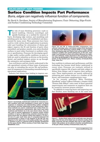
- 1. AIRLINE/AIRCRAFT PARTS FINISHING Surface Condition Impacts Part Performance Burrs, edges can negatively influence function of components. By David A. Davidson, Society of Manufacturing Engineers, Chair: Deburring, Edge-Finish and Surface Conditioning Technology Committee T he role of mass finishing processes—such as barrel tumbling, vibratory, centrifugal, and spindle finishing—as a method for removal of burrs, developing edge contour, and smoothing and polishing parts has been well established and docu- mented for many years. These processes have been used in a wide variety of part applications to promote safer part handling (by attenuation of sharp part edges); improve the fit and function of parts when assembled; and produce smooth, even micro-finished surfaces to meet either functional or aesthetic crite- ria or specifications. Processes for developing specif- ic edge and/or surface profile conditions on parts in bulk are used in industries as diverse as the jewelry, dental, and medical implant sectors on up through the automotive and aerospace fields. Less well known and less clearly understood is the role specialized variants of these types of processes can play in extending the service life and perform- ance of components in demanding manufacturing or operational applications. Industry has always been looking to improve sur- face condition to enhance part performance, and this technology has become much better understood in recent years. Processes are routinely utilized to specifically improve life of parts and tools subject to failure from fatigue and to improve their perform- ance. These improvements are mainly achieved by enhancing part surface texture in a number of dif- ferent, and sometimes complementary, ways. In his recently published “Mass Finishing Handbook” author LaRoux Gillespie a chapter titled “Process Side Effects” notes some of these potential improvements and comments on negatives that can be caused by incorrect process selection: “In addition to removing burrs and improving sur- face finishes, mass finishing can at the same time xx www.metalfinishing.com Figure 1: Increasingly sophisticated methods for measuring sur- face condition have been developed in recent years to assist engineers in analyzing and understanding surface conditions and textures and their relationship to part performance. Often, these methods are used to understand how surface finish tex- tures meet operational requirements after parts have been machined and finished. As in the case shown above, they are also used in forensic applications to measure current surface condition in terms of determining potential remaining opera- tional service life. The diagram shown here depicts a 1.5 mm x 7.5 mm of a gear tooth wear area. A computer-enhanced 3-D characterization is shown on the diagram to the left; the two diagrams to the right show a 2-D surface profile trace.The part in question is part of a gear-box built by Hamilton Sundstrand for the space shuttle. (Photo courtesy of Jack Clark; Zygo Corp., Middlefield, Conn. Figure 2A and 2B: In before-and-after comparisons, burr removal, hole-edge radius, and interior surface finish developed by Abrasive Flow Machining method (AFM). In many applica- tions, developing edge and interior hole surface quality are CTQ (critical to quality) and overall performance of the part, espe- cially if non-turbulent air flow and air-flow efficiency are impor- tant part attributes. Easily discerned in the comparison of the two close-up photographs is the isotropic surface finish charac- teristic of the finished part. (Photo courtesy of Extrude-Hone Corp., Irwin, Pa.) Figure 3 — Surface finish values of the small holes seen along the edge of the foil area of the blade here are critical to cooling of the blade. Improved and less turbulent flow due to high quality of interior hole surfaces can be critical to function and performance of the part. (Photo courtesy of Extrude-Hone, Irwin, Pa.)
- 2. change other key attributes of parts, some for the worse and others for the better. In addition to removing burrs, mass finishing can: • Radius or blunt part edges; • change part dimensions (0.000050 in.–0.003 in.); • change a part’s surface finish; • compact a part’s surface pores; • clean a part’s oily and dirty surfaces; • remove oxides and heavy scale from parts; • change a part’s flatness; • prevent soldering (if wrong abrasives are used); • create large compressive stresses in part; • improve or worsen corrosion rates; • change part luster; • change part color; • change friction; • and decontaminate radioactive surfaces. AEROSPACE EDGE/SURFACE QUALITY CONCERNS Sometimes, to fully understand the significance of edge and surface quality issues, it is important to understand the magnitude of the consequences when edge and surface condition receive insufficient attention. Gillespie, when summarizing some points made in an aerospace forum regarding edge and surface quality issues, noted that important service and operational considerations can be heavily impacted by edge and surface condition quality: Fatigue life, stresses, and strain: Fatigue life increases with decreasing surface roughness, and smoother surfaces have less preload loss when they are part of a mechanically fastened joint. Burrs increase stress concentration at hole edges, which already have three times the net section stress at the edge. Therefore, removing burrs decreases stress con- centration, which increases fracture resistance and fatigue life. Lastly, burrs can interfere with proper seating of mechanical fasteners, so removing them reduces damage to fasteners and clamped components during assembly. Sharp corners increase stress concentration, so increasing radii decreases stress concentration, which increases fracture resistance and fatigue life. If water creeps under interfaces via higher surface roughness and fills up a cavity or interface, then freezes, it could create high stresses and/or acceler- ate material fracture, not to mention stress corro- sion cracking at scores from the hidden, trapped water/chemicals. One author notes, “Sharp corners, burr holes, etc. increase not only the stress but the strain as well. Looking at the strain we can have three different situations: 1. The strain can be inside the linear behavior. (Under the yield limit). 2. The strain can be between the ultimate and the yield limit. 3. The strain can reach the ultimate limit. If the third situation is going to occur, the cracks can develop because of material failure. In this case, the crack can also reach the material’s “critical value.” For this reason, round the corners, deburring the holes, and finishing the surfaces will help to pass from the third to the first situation.” Almost without exception fatigue cracks start at the surface of a part rather than internally. One pos- sible reason may be that the highest stresses are usually found at the surface (e.g., bending and tor- sion) and the surface is vulnerable to stress raisers, such as machining notches, scratches, and pits. Surface finish affects the strength of a part subject- ed to fatigue loading because most machining oper- ations leave a notch pattern and fatigue cracks usu- ally originate in a notch.” Corrosion and coating impact: Poor surface finish introduces millions of new points for crevice corrosion on the surface. Also, a rough surface can AIRLINE/AIRCRAFT PARTS FINISHING xx www.metalfinishing.com Figure 5: Impeller-like parts can be processed with Centrifugal Barrel Finishing (CBF); Turbo-Finish (TAM), and Abrasive Flow Machining (AFM) methods to produce uniform edge contours, but part performance is enhanced by the isotropic and plateaud surfaces created in the foil area of the part. Figure 4: Aircraft engine vane segments can be deburred, radiused, and are polished with a number of different methods. These components processed with centrifugal barrel finishing (CBF), which has developed needed edge and surface finishes while developing high-quality surfaces with useful stress and isotropic characteristics.
- 3. February 2007 xx make it difficult to get good results with non-destructive testing methods like die pene- trants—especially when the roughness is in a pattern (such as produced by flycutting or milling). Rougher surfaces or sharper exterior edges can scratch coated or painted sur- faces during assembly and might allow hidden corrosion to spread underneath what might tem- porarily appear as good finishes. The physics, electrochemistry, etc., are well documented about applying a coating to a sharp edge. When using any type of electrically catalyzed process (anodizing, electrocoating, elec- trostatic spray painting, etc.) current density fluctuations pre- vent the build-up of a uniform coating thickness. Variations in coating thickness have many negative aspects, such as vari- able friction at joint surfaces, areas for localized corrosion, pit- ting, galvanic cells, etc. Corrosion fatigue and stress corrosion cracking are obvious concerns. Joint friction and preloads: Also, with riveted structure, fric- tion (due to the clamping force of the fasteners) between faying surfaces in a joint serves a cou- ple important functions. First, the friction provides a bit of “shear preload”—the joint can take a certain amount of shear without loading the fasteners or sheet in bearing. The greater the friction, the more resistant the joint will be to working loose and smoking rivets. This ties in nicely to the second function: high frequency (engine) vibrations throughout the structure are damped or dissipated through joint friction. The greater the fric- tion, the greater the high-frequen- cy-fatigue resistance of a mechan- ically fastened joint. If a burr is sitting between the fastened sheets preventing good contact of the faying surfaces, much of this friction is lost. A higher surface roughness will lead to higher friction forces to overcome when torquing a bolt. This means that less preload (Fi) will be developed, with a corre- sponding decrease in load at which gapping occurs [Fi/(1-C)], which increases chances for leaks (stuff coming out, or stuff going in), and also leads to worse fatigue performance (higher alternating tensile stresses). A higher surface roughness may also lead to preload relaxation— exacerbating all of the above. As one reader noted, “This is the classic ‘shanking and sheet gapping’ syndrome, caused by burrs and ‘liberated burrs’ [chips].” Rough surfaces provide less surface area of contact, giv- ing rise to higher and very local- ized contact stresses. If flavored with a little salt mixed in and throw in some corrosion, this could be a disaster. Good seating: A fastener hole with a good, sharp, burred corner will have obvious problems with seating when met with a fasten- er that has a radiused junction between head and shank. Poor bonding of structures, in light- ning strikes, can cause cata- strophic local structural failure. Static discharge: Sharp out- side corners on structure act as electrical charge concentrators, and can be a static discharge haz- ard. For the same reason, sharp corners can cause undesirable results in electroplating opera- tions. One reader asks, “If an over- ly rough surface causes corrosion, could this joint develop a static charge?” If there are two conduc- tive metal surfaces separated by a dielectric (oxide) and you add some movement or vibration—presto— static charge because of rough sur- faces (as opposed to burrs). Issues between moving parts: Mating faces must be finely machined (or finished) to: AIRLINE/AIRCRAFT PARTS FINISHING Figure 6: Centrifugal bar- rel finishing was used to change the character of surfaces on this titanium test coupon. Centrifugal, vibratory, and AFM meth- ods are being used to change surface character- istics that can affect part performance. The upper coupon is typical of as machined (milling cutter- path or ground) surfaces with a positively skewed surface has been altered to exhibit a plateaued surface with attenuated or blended peaks, shown in the lower test coupon. Figure 7: Centrifugal barrel machine preparing to process aircraft vane seg- ments, deburring vane edges and also smoothing and polishing the foil surface areas simultaneously. (Photo courtesy of Tom Mathisen, MFI.)
- 4. xx www.metalfinishing.com AIRLINE/AIRCRAFT PARTS FINISHING • Avoid friction; • avoid heat due to friction. Excessive heat may change the properties of the material surface, with unpredictable consequences; • have better lubrication. The active film in a fine machined surface will be more efficient because there will be more surface in contact with the lubricant. This will permit better heat transfer from the part to the lubricant (there is a limit to how fine a finish a surface should have. The auto- motive industry intentionally adds some surface patterns to hold the oil in internal combustion engines; • excessive roughness may develop high material wear, leading to high play, and high replace fre- quencies of the parts; • roughness produces friction as stated above. Friction can lead to electricity (tribo-electric effect). Electricity can lead to corrosion. Electrical issues: As noted above, friction between rough surfaces will create electrical energy. That energy can create an accelerated galvanic-cor- rosion anode or cathode site, if all (most) other sur- faces are coated or insulated. Burrs are sources of static discharge. Burrs and surface roughness will both interfere with good, uniform surface contact between faying surfaces in a mechanical joint. This increases the electrical resistance of the joint and, if severe, can cause problems with electrical bonding of structure; interfering with effective grounding of electrical equipment and/or antennae, and become a minia- ture plasma cutter in the event of a lightning strike. Current density due to sharp edges and burrs can cut through protective coatings on mating surfaces and radii, providing a minute area of “clean metal” electrical path to drive corrosion dramatically worse than if no protective coating were there to begin with due to the extremely high resultant current density. The hole-punching force of high current density results in stress risers to enhance SCC and corrosion fatigue. For aircraft assemblies, sharp edges become spark over points whenever voltage is applied (static, lightning strikes, etc.) Hydraulic and gas leaks: Higher values of sur- face roughness (and burrs) increase leakage rate under/around gaskets and seals. Nipping gaskets, seals, and O-rings on sharp edges during installation, or scouring them on rougher surfaces during opera- tion of rotating equipment, can accelerate leakage. Sometimes a surface that is finished too well can hinder sealing. O-rings need something to hold on to —if your surface finish is too fine and the compres- sion on the O-ring is too light, the O-ring is likely to fail. In one industry, engineers specify 63ra for most surfaces that will contact a secondary sealing ele- ment. (They do, however, require flatness and sur- face finish to an extreme on other parts—millionths of an inch for mechanical seal faces). There are times when a sharp edge is needed. Labyrinth seals in gas turbines spring to mind, as do squealer tips on compressor blades. Peening issues: Excessive surface roughness can sometimes be an indication of over-peening, which negates the beneficial aspects of compressive resid- ual stress. Aluminum and magnesium are especial- ly prone to over-peening, which results in many localized areas of increased stress. Problems with fracture (stress intensity) and fatigue (crack nucle- ation sites) are then possible/probable. Joint prob- lems can arise from excessive surface roughness, and over-peening is yet another method for creating surface roughness. Shot peening, mass finishing, surface polishing, deburring, and rounding off all add a sustained com- pressive stress into the material. This stress will counteract the tensile stress caused by a crack and help to contain its propagation. EDGE AND SURFACE CONDITIONS THAT INFLUENCE PART PERFORMANCE To understand how edge and surface quality can impact part performance, some understanding of how part surfaces developed from common machin- ing, grinding, and other methods can negatively influence part function over time. A number of fac- tors are involved: Positive vs. negative surface skewness: The skew of surface profile symmetry can be an important surface attribute. Surfaces are typically characterized as being either negatively or positively skewed. This surface characteristic is referred to as Rsk (Rsk–skew- ness–the measure of surface symmetry about the mean line of a profilometer graph). Unfinished parts usually display a heavy concentration of surface peaks above this mean line (a positive skew). It is axiomatic that almost all surfaces produced by common machining and fabrication methods are positively skewed. These positively skewed surfaces have an undesirable effect on the bearing ratio of surfaces, negatively impacting the performance of parts involved in applications where there is sub- stantial surface-to-surface contact. Specialized high- energy finishing procedures can truncate these sur- face profile peaks and achieve negatively skewed surfaces that are plateaued, presenting a much higher surface bearing contact area. Anecdotal evi- dence confirms that surface finishing procedures
- 5. 5 Metal Finishing AIRLINE/AIRCRAFT PARTS FINISHING tailored to develop specific surface conditions with this in mind can have a dramatic impact on part life. In one example, the life of tooling used in aluminum can stamping operations was extended 1,000% or more by improved surface textures produced by mechanical sur- face treatment. Directionalized vs. ran- dom (isotropic) surface texture patterns: Somewhat related to surface texture skewness in importance is the directional nature of surface textures developed by typical machining and grinding methods. These machined surfaces are characterized by tool marks or grinding pat- terns that are aligned and directional in nature. It has been established that tool or part life and performance can be substantially enhanced if these types of surface tex- tures can be altered into one that is more random in nature. Post-machining processes that utilize free or loose abrasive materials in a high-energy context can alter the machined surface texture sub- stantially, not only reducing sur- face peaks, but generating a sur- face in which the positioning of the peaks has been altered appre- ciably. These “isotropic” surface effects have been demonstrated to improve part wear and fracture resistance, bearing ratio and improve fatigue resistance. Residual tensile stress vs. residual compressive stress. Many machining and grinding processes tend to develop resid- ual tensile stresses in the surface area of parts. These residual ten- sile stresses make parts suscepti- ble to premature fracture and failure when repeatedly stressed. Certain high-energy mass finish- ing processes can be implement- ed to modify this surface stress condition, and replace it with uniform residual compressive stresses. Although, there are many mechanical surface treat- ments that will improve edge and surface finish quality. A number of processes are now specified specifically because of their repu- tation as performance-enhancing processes, some of these are dis- cussed below. Abrasive flow machining (AFM) is a process that, under pressure, extrudes a semisolid abrasive media that conforms to the shape of the surface or pas- sage that is being processed. Polishing, deburring, and edge radiusing are accomplished any- where that the media can be forced to flow. The abrasive flow polished surface has no smeared metal, and the radii generated on any 90 degree edges are true radii. The elimination of stress risers, damaged metal layers, and the generation of round edges are used to help extend component life. Rotating parts can especially benefit from the AFM process. Fans, blisks, blades, disks, and spacers can all benefit from this surface and edge conditioning. Highly polished surfaces also tend to pick up less coke and car- bon. This is especially important on fuel systems components. Blades and vanes located in both the cool and warm sections of the Figure 8: The Turbo-finish method, more commonly used for process rotating air- craft engine parts, not only deburrs and produces edge contour, but also develops compressive stress equilibri- um and isotropic surface val- ues that can be critical to part life in service. (Courtesy Dr. Michael Massarsky, Turbo-Finish Corporation.) Figure 9: Large aircraft frame parts can be deburred, simi- lar machinery can also be used with steel media to produce important residual compressive stress in aircraft frame components, an important consideration for large titanium components such as the one illustrated here. (Photo courtesy of Samuel R.Thompson.)
- 6. 6 Metal Finishing AIRLINE/AIRCRAFT PARTS FINISHING engine can also benefit from highly polished sur- faces in less turbulent air flow across their surfaces. The abrasive flow process imparts compressive residual stress. Although it will never replace shot peening, it is used to extend part life on components that, by configuration, cannot be shot peened. The process is used to enhance holes and slots prior to eddy current inspection. Many components that are being inspected as part of an engine over- haul are hand polished (butterflied) prior to inspec- tion. The hand process is inconsistent and time con- suming. AFM can be managed so that only the coke and carbon are removed, greatly optimizing the inspection process. Small holes on fuel system com- ponents and turbine blades and vanes can be flow tuned to ±1%. By more efficiently tuning cooling air, hot section components will last longer and require less air. Fuel-delivery components benefit from more uniformity in both spray shape and flow rate. AFM is used as the final machining and sizing operation. The AFM process can be used to control stock removal to ±0.0001 of an inch. CENTRIFUGAL BARREL FINISHING Centrifugal barrel finishing (CBF) is a high-energy finishing method (see Figure 4) that has come into widespread acceptance in the last 25 to 30 years. Although not nearly as universal in application as vibratory finishing, many important CBF applica- tions have been developed in the last few decades. These kinds of processes are utilized widely within the aerospace and aircraft engine industries because of their ability to produce high-quality isotropic surface finishes rapidly on parts, such as turbine blades and vane segments and developing useful compressive stress values simultaneously. Two or four barrels are mounted at the periphery of a large turret. Each barrel is loaded with media, parts, and water to approximately 50% to 90% full. During operation, rotation of the large turret creates a centrifugal force on the media and parts inside each barrel. This force compacts the load into a tight mass, causing the media and parts to slide against each other, removing burrs and creating superior finishes. This action also reduces the cycle time needed to com- plete the finishing of the parts by up to a factor of 30 over conventional vibratory and barrel equipment. Turbo-finish and performance issues: This technology has been demonstrated to successfully impart compressive stresses into critical areas of rotat- ing parts in a fashion that is unique. The method is also capable of producing surface conditions at these critical edge areas that contribute to increased service life and functionality of parts that are severe- ly stressed in service. Among these are: (1) the cre- ation of isotropic surfaces; (2) the replacement of pos- itively skewed surface profiles with negative or neutral skews; and (3) the development of an overall stress equilibrium in parts with a complex feature set. As previously mentioned, all common machining and manual finishing methods produce uneven stress hot-spots in machined parts. This occurs because of the rapid rise and fall of temperature on metal surfaces at the tool or wheel point of contact. TAM not only produces beneficial compressive stresses, but also in many cases, where all surfaces and features are effected identically and simultane- ously, can promote a stress equilibrium or uniformi- ty throughout the entire part. Thus, TAM could be looked at as a corrective after process for critical parts that suffer from these machining-related sur- face integrity issues. The synergy involved in developing these kinds of effects can add a potential value to service life, per- formance, and functionality of parts that far exceeds the value of the improvements to fit, function, and aesthetics commonly associated with other mechan- ical or mass finishing processes. Unlike single-point- of-contact machining technologies, the technology is relatively simple to control once process parameters for a given part have been developed and, thus, has the attributes of reliability and repeatability of sim- pler mechanical (vs. digital feedback) technologies. However, it accomplishes uniform results on very complex parts that often cannot be achieved reliably by other much more complex processes. The technology involves developing a fluidized bed of media in which the part to be processed is par- tially immersed while being rotated. A wide variety of differing results may be achieved by varying the process parameters (media, process time, rotational speed, etc.). Process results can be closely controlled and are programmable, and are totally repeatable, providing unequaled process quality control. The process is dry, and involves no chemicals or environ- mentally unfriendly materials. VIBRATORY FINISHING LARGE AEROSPACE COMPONENTS Vibratory equipment can be designed to accommodate Figure 10: Metallic media, such as the steel media shapes illustrated here, have long been known to develop com- pressive stress in barrel and vibratory finishing opera- tions while burnishing, and cleaning part surfaces. This capability is now being used in larger sized equipment to strengthen large airframe components. Photo courtesy of Abbott Ball Co.
- 7. 7 Metal Finishing AIRLINE/AIRCRAFT PARTS FINISHING aircraft components of extraordinary size. Large com- ponents, such as aircraft engine cases and airframes, can be finished with this method, not only cutting the extensive costs related to manual deburring but improving the uniformity and quality of edge and sur- face finish quality. Additionally, these processes can develop not only useful compressive stress but pro- vide something very much like a stress equilibrium enhancement throughout the part, as all part features can be processed identically. Modified methods origi- nally developed in the former Soviet Union with metallic media can also be used to intensify this effect, and has even been used to restore useful serv- ice life to stressed or strained parts in overhaul cycles. SUMMARY Many parts that are subject to fatigue, fracture, or wear can gain substantial improvements in life and performance from alterations to their overall sur- face texture. Improvements in overall smoothness, load bearing ratio, surface profile skewness and isotropicity can, in many instances, improve life and performance and cut operational costs. REFERENCES Gillespie, LaRoux, “Mass Finishing Handbook,” Society of Manufacturing Engineers, (New York, Industrial Press) p. 61; 2007. Gillespie, LaRoux, “Compiled Problems Caused by Burrs and Sharp Edges,” (Spokane, Wash: Society of Manufacturing Engineers, Deburring, Edge-Finish and Surface Conditioning Technical Group, Spokane), Newsletter, Vol 2, No. I, January 8, 2006, [Davidson, D.A., ed.]; 2006. Davidson, D.A., “Mass Finishing Processes,” 2005 Metal Finishing Guidebook and Directory, 103(6A):78–89; 2005. Massarsky, M. L., Davidson, D. A., “Turbo-Abrasive Machining and Turbo-Polishing in the Continuous Flow Manufacturing Environment”, SME Technical Paper MR99-264, Conference Proceeding: 3rd International Machining and Grinding Conference, Cincinnati, Oct 4–7, 1999, Dearborn, Mich.: Society of Manufacturing Engineers, 1999. Gane, David H., Rumyantsev, H.T., Diep, Bakow, L. “Evaluation of Vibrostrengthening for Fatigue Enhancement of Titanium Structural Components on Commercial Aircraft.” Ti-2003 Science and Technology; Proceedings of the 10th World Conference on Titanium, Hamburg Germany, 13–18 July 2003, Edited by G. Lutejering and J Albrecht. Wiley-VCH, Vol. 2. pp 1053–1058. Massarsky, M. L., Davidson, D. A., “Turbo-Abrasive Machining,” CODEF PROCEEDINGS, 7th International Deburring Conference, Berkeley, Calif.: CODEF [Consortium on Deburring and Edge Finishing], University of California at Berkeley; June 2004. ACKNOWLEDGEMENTS The author wishes to acknowledge the technical assistance of the following members of the newly formed Society of Manufacturing Engineers DESC Technical Group [Deburring, Edge-Finish, Surface Conditioning]. Dr. Michael Massarsky, Turbo-Finish Corporation; David H. Gane, Boeing; Edward F. Rossman Ph. D., Boeing; Jack Clark, ZYGO Corporation; LaRoux Gillespie, PE, CmfgE, Rodney Grover, Society of Manufacturing Engineers. For more information, please contact the author at (e-mail) ddavidson@mgnh.dyndns.org. mf