Surface Roughness: Terminology and types
•Download as DOCX, PDF•
7 likes•6,008 views

Banner type file

Recommended
More Related Content
What's hot
What's hot (20)
Similar to Surface Roughness: Terminology and types
Similar to Surface Roughness: Terminology and types (20)
Recently uploaded
Recently uploaded (20)
Surface Roughness: Terminology and types
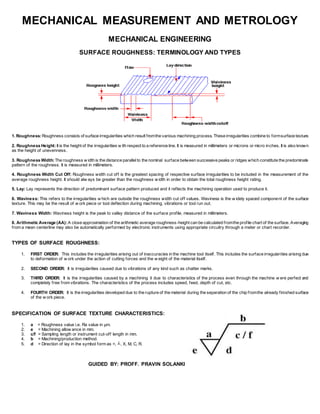
- 1. MECHANICAL MEASUREMENT AND METROLOGY MECHANICAL ENGINEERING SURFACE ROUGHNESS: TERMINOLOGY AND TYPES 1. Roughness:Roughness consists of surface irregularities which result fromthe various machining process. These irregularities combine to formsurface texture. 2. Roughness Height:It is the height of the irregularities w ith respect to a reference line. It is measured in millimeters or microns or micro inches. It is also known as the height of unevenness. 3. Roughness Width:The roughness w idth is the distance parallelto the nominal surface between successive peaks or ridges which constitute the predominate pattern of the roughness. It is measured in millimeters. 4. Roughness Width Cut Off: Roughness width cut off is the greatest spacing of respective surface irregularities to be included in the measurement of the average roughness height. It should alw ays be greater than the roughness w idth in order to obtain the total roughness height rating. 5. Lay: Lay represents the direction of predominant surface pattern produced and it reflects the machining operation used to produce it. 6. Waviness: This refers to the irregularities w hich are outside the roughness width cut off values. Waviness is the w idely spaced component of the surface texture. This may be the result of w ork piece or tool deflection during machining, vibrations or tool run out. 7. Waviness Width: Waviness height is the peak to valley distance of the surface profile, measured in millimeters. 8. Arithmetic Average (AA): A close approximation of the arithmetic average roughness-height can be calculated fromthe profile chart of the surface. Averaging from a mean centerline may also be automatically performed by electronic instruments using appropriate circuitry through a meter or chart recorder. TYPES OF SURFACE ROUGHNESS: 1. FIRST ORDER: This includes the irregularities arising out of inaccuracies in the machine tool itself. This includes the surface irregularities arising due to deformation of w ork under the action of cutting forces and the w eight of the material itself. 2. SECOND ORDER: It is irregularities caused due to vibrations of any kind such as chatter marks. 3. THIRD ORDER: It is the irregularities caused by a machining it due to characteristics of the process even through the machine w ere perfect and completely free from vibrations. The characteristics of the process includes speed, feed, depth of cut, etc. 4. FOURTH ORDER: It is the irregularities developed due to the rupture of the material during the separation of the chip fromthe already finished surface of the w ork piece. SPECIFICATION OF SURFACE TEXTURE CHARACTERISTICS: 1. a = Roughness value i.e. Ra value in µm. 2. e = Machining allow ance in mm. 3. c/f = Sampling length or instrument cut-off length in mm. 4. b = Machining/production method. 5. d = Direction of lay in the symbol form as =, ┴, X, M, C, R. GUIDED BY: PROFF. PRAVIN SOLANKI