Phase diagrams provide information about the equilibrium conditions and transformations between different phases in a material system. They describe how the phases of a material vary with changes in temperature, pressure, and composition.
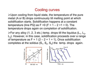
This document discusses key concepts related to phase diagrams including phases, the Gibbs phase rule, one-component and binary phase diagrams, eutectic and peritectic reactions, intermediate phases, ternary diagrams, and lever rule. It provides examples of phase diagrams for common material systems like water, Cu-Ni, Pb-Sn, Mg-Pb, and Cu-Zn. Cooling curves are also explained to illustrate phase transformations.
CORE LOSS,COPPER LOSS,EDDY CURRENT,HYSTERESIS LOSS OF TRANSFORMER| DAY6|BASIC...Prasant Kumar
#CORE_COPPER_LOSS_EDDY_CURRENT_HYSTERESIS_LOSS
#CORE_LOSS_OF_TRANSFORMER
#COPPER_LOSS_OF_TRANSFORMER
#EDDY_CURRENT_OF_TRANSFORMER
#HYSTERESIS_LOSS_OF_TRANSFORMER
#BASIC ELECTRICAL ENGINEERING
In this video you will learn
Transformer ,Day 6, core loss,copper loss,eddy cuurent loss, Basic electrical and electronics engineering.
Transformer is a static device, hence mechanical losses (like friction loss) are absent in it. A transformer only consists of electrical losses (iron losses and copper losses).
Core Loss Or Iron Loss Or Constant loss:
Core losses are due to the magnetic properties of the material used for the construction of core.
Core is made by iron like CRGO so called iron loss.
Core loss is treated as constant at rated voltage and frequency, so called constant loss.
Eddy current loss:
Sodium vapour lamp construction , working of sodium vapour lamp, advantages and disadvantages of sodium vapour lamp, explanation of sodium vapour lamp, what is sodium vapour lamp, application of sodium vapour lamp . All information covers in this ppt.
TALAT Lecture 1202: Metallography of Aluminium AlloysCORE-Materials
This lecture aims at providing a survey of the metallographic techniques available for the examination of aluminium and its alloys. The information must be sufficient to be sure that the students and the users are able to choose the most suitable technique to solve their problems in the examination of samples. The lecture should contain a direct understanding of the main problems in the metallography of the different classes of aluminium materials.
The apparatus used for switching, controlling & protecting the electrical circuits & equipments are known as switchgear.
The switchgear equipments is essentially used with switching & interrupting currents either under normal or abnormal operating condition.
It consists of devices such as switches, fuses, circuit breakers, relays etc.
Basically every electric circuit needs a switching device & a protecting device.
The single-phase motor, which are designed to operate from a single-phase supply, are manufactured in a large number of types to perform a wide variety of useful services in home, offices, factories, workshops and in a business establishments etc.
Small motors, particularly in the frictional kW sizes are better known than any other. In fact, most of the new products of the manufacturers of space vehicles, aircrafts, business machines and power tools etc. have been possible due to of the advances made in the design of frictional kW motors. Since the performance requirements of the various applications differ so widely, the motor manufacturing industry has developed many different types of such motors, each being designed to meet specific demands.
Single-phase motors may be classified as under, depending on their construction and method of starting:
1. Induction Motors (split-phase, capacitor and shaded-pole etc.)
2. Repulsion Motors (sometime called inductive-series motor)
3. AC Series Motor, and
4. Un-excited Synchronous Motors
Phase diagrams for Different Alloy
By
P.SENTHAMARAIKANNAN,
ASSISTANT PROFESSOR ,
DEPARTMENT OF MECHANICAL ENGINEERING,
KAMARAJ COLLEGE OF ENGINEERING AND TECHNOLOGY,
VIRUDHUNAGAR, TAMILNADU,
INDIA
Ekeeda Provides Online Engineering Subjects Video Lectures and Tutorials of Mumbai University (MU) Courses. Visit us: https://ekeeda.com/streamdetails/University/Mumbai-University
This document is about phases and phase diagram's interpretation. It includes information regarding compositional quantity, each phase quantity, overall composition, etc. It also tells about how to read a phasor diagram along with information regarding various components of these kinds of diagrams.
Industrial Training at Shahjalal Fertilizer Company Limited (SFCL)MdTanvirMahtab2
This presentation is about the working procedure of Shahjalal Fertilizer Company Limited (SFCL). A Govt. owned Company of Bangladesh Chemical Industries Corporation under Ministry of Industries.
NO1 Uk best vashikaran specialist in delhi vashikaran baba near me online vas...Amil Baba Dawood bangali
Contact with Dawood Bhai Just call on +92322-6382012 and we'll help you. We'll solve all your problems within 12 to 24 hours and with 101% guarantee and with astrology systematic. If you want to take any personal or professional advice then also you can call us on +92322-6382012 , ONLINE LOVE PROBLEM & Other all types of Daily Life Problem's.Then CALL or WHATSAPP us on +92322-6382012 and Get all these problems solutions here by Amil Baba DAWOOD BANGALI
#vashikaranspecialist #astrologer #palmistry #amliyaat #taweez #manpasandshadi #horoscope #spiritual #lovelife #lovespell #marriagespell#aamilbabainpakistan #amilbabainkarachi #powerfullblackmagicspell #kalajadumantarspecialist #realamilbaba #AmilbabainPakistan #astrologerincanada #astrologerindubai #lovespellsmaster #kalajaduspecialist #lovespellsthatwork #aamilbabainlahore#blackmagicformarriage #aamilbaba #kalajadu #kalailam #taweez #wazifaexpert #jadumantar #vashikaranspecialist #astrologer #palmistry #amliyaat #taweez #manpasandshadi #horoscope #spiritual #lovelife #lovespell #marriagespell#aamilbabainpakistan #amilbabainkarachi #powerfullblackmagicspell #kalajadumantarspecialist #realamilbaba #AmilbabainPakistan #astrologerincanada #astrologerindubai #lovespellsmaster #kalajaduspecialist #lovespellsthatwork #aamilbabainlahore #blackmagicforlove #blackmagicformarriage #aamilbaba #kalajadu #kalailam #taweez #wazifaexpert #jadumantar #vashikaranspecialist #astrologer #palmistry #amliyaat #taweez #manpasandshadi #horoscope #spiritual #lovelife #lovespell #marriagespell#aamilbabainpakistan #amilbabainkarachi #powerfullblackmagicspell #kalajadumantarspecialist #realamilbaba #AmilbabainPakistan #astrologerincanada #astrologerindubai #lovespellsmaster #kalajaduspecialist #lovespellsthatwork #aamilbabainlahore #Amilbabainuk #amilbabainspain #amilbabaindubai #Amilbabainnorway #amilbabainkrachi #amilbabainlahore #amilbabaingujranwalan #amilbabainislamabad
Hierarchical Digital Twin of a Naval Power SystemKerry Sado
A hierarchical digital twin of a Naval DC power system has been developed and experimentally verified. Similar to other state-of-the-art digital twins, this technology creates a digital replica of the physical system executed in real-time or faster, which can modify hardware controls. However, its advantage stems from distributing computational efforts by utilizing a hierarchical structure composed of lower-level digital twin blocks and a higher-level system digital twin. Each digital twin block is associated with a physical subsystem of the hardware and communicates with a singular system digital twin, which creates a system-level response. By extracting information from each level of the hierarchy, power system controls of the hardware were reconfigured autonomously. This hierarchical digital twin development offers several advantages over other digital twins, particularly in the field of naval power systems. The hierarchical structure allows for greater computational efficiency and scalability while the ability to autonomously reconfigure hardware controls offers increased flexibility and responsiveness. The hierarchical decomposition and models utilized were well aligned with the physical twin, as indicated by the maximum deviations between the developed digital twin hierarchy and the hardware.
Explore the innovative world of trenchless pipe repair with our comprehensive guide, "The Benefits and Techniques of Trenchless Pipe Repair." This document delves into the modern methods of repairing underground pipes without the need for extensive excavation, highlighting the numerous advantages and the latest techniques used in the industry.
Learn about the cost savings, reduced environmental impact, and minimal disruption associated with trenchless technology. Discover detailed explanations of popular techniques such as pipe bursting, cured-in-place pipe (CIPP) lining, and directional drilling. Understand how these methods can be applied to various types of infrastructure, from residential plumbing to large-scale municipal systems.
Ideal for homeowners, contractors, engineers, and anyone interested in modern plumbing solutions, this guide provides valuable insights into why trenchless pipe repair is becoming the preferred choice for pipe rehabilitation. Stay informed about the latest advancements and best practices in the field.
About
Indigenized remote control interface card suitable for MAFI system CCR equipment. Compatible for IDM8000 CCR. Backplane mounted serial and TCP/Ethernet communication module for CCR remote access. IDM 8000 CCR remote control on serial and TCP protocol.
• Remote control: Parallel or serial interface.
• Compatible with MAFI CCR system.
• Compatible with IDM8000 CCR.
• Compatible with Backplane mount serial communication.
• Compatible with commercial and Defence aviation CCR system.
• Remote control system for accessing CCR and allied system over serial or TCP.
• Indigenized local Support/presence in India.
• Easy in configuration using DIP switches.
Technical Specifications
Indigenized remote control interface card suitable for MAFI system CCR equipment. Compatible for IDM8000 CCR. Backplane mounted serial and TCP/Ethernet communication module for CCR remote access. IDM 8000 CCR remote control on serial and TCP protocol.
Key Features
Indigenized remote control interface card suitable for MAFI system CCR equipment. Compatible for IDM8000 CCR. Backplane mounted serial and TCP/Ethernet communication module for CCR remote access. IDM 8000 CCR remote control on serial and TCP protocol.
• Remote control: Parallel or serial interface
• Compatible with MAFI CCR system
• Copatiable with IDM8000 CCR
• Compatible with Backplane mount serial communication.
• Compatible with commercial and Defence aviation CCR system.
• Remote control system for accessing CCR and allied system over serial or TCP.
• Indigenized local Support/presence in India.
Application
• Remote control: Parallel or serial interface.
• Compatible with MAFI CCR system.
• Compatible with IDM8000 CCR.
• Compatible with Backplane mount serial communication.
• Compatible with commercial and Defence aviation CCR system.
• Remote control system for accessing CCR and allied system over serial or TCP.
• Indigenized local Support/presence in India.
• Easy in configuration using DIP switches.
Immunizing Image Classifiers Against Localized Adversary Attacksgerogepatton
This paper addresses the vulnerability of deep learning models, particularly convolutional neural networks
(CNN)s, to adversarial attacks and presents a proactive training technique designed to counter them. We
introduce a novel volumization algorithm, which transforms 2D images into 3D volumetric representations.
When combined with 3D convolution and deep curriculum learning optimization (CLO), itsignificantly improves
the immunity of models against localized universal attacks by up to 40%. We evaluate our proposed approach
using contemporary CNN architectures and the modified Canadian Institute for Advanced Research (CIFAR-10
and CIFAR-100) and ImageNet Large Scale Visual Recognition Challenge (ILSVRC12) datasets, showcasing
accuracy improvements over previous techniques. The results indicate that the combination of the volumetric
input and curriculum learning holds significant promise for mitigating adversarial attacks without necessitating
adversary training.
Welcome to WIPAC Monthly the magazine brought to you by the LinkedIn Group Water Industry Process Automation & Control.
In this month's edition, along with this month's industry news to celebrate the 13 years since the group was created we have articles including
A case study of the used of Advanced Process Control at the Wastewater Treatment works at Lleida in Spain
A look back on an article on smart wastewater networks in order to see how the industry has measured up in the interim around the adoption of Digital Transformation in the Water Industry.
Overview of the fundamental roles in Hydropower generation and the components involved in wider Electrical Engineering.
This paper presents the design and construction of hydroelectric dams from the hydrologist’s survey of the valley before construction, all aspects and involved disciplines, fluid dynamics, structural engineering, generation and mains frequency regulation to the very transmission of power through the network in the United Kingdom.
Author: Robbie Edward Sayers
Collaborators and co editors: Charlie Sims and Connor Healey.
(C) 2024 Robbie E. Sayers
2. Phase
A phase can be defined as a physically distinct and chemically
homogeneous portion of a system that has a particular
chemical composition and structure.
Water in liquid or vapor state is single phase. Ice floating on
water is an example two phase system.
Gibbs Phase rule
The number of degrees of freedom, F (no. of independently
variable factors), number of components, C, and number of
phases in equilibrium, P, are related by Gibbs phase rule as
F = C – P + 2
Number of external factors = 2 (pressure and temperature).
For metallurgical system pressure has no appreciable effect on
phase equilibrium and hence, F = C – P + 1
3. Phase Diagrams
One component system
The simplest phase diagram is the water which is a one
component system. It is also known as pressure-temperature or
P-T diagram. Two phases exist along each of the three phase
boundaries. At low pressure (0.006 atm) and temperature (0.01
C) all the three phases coexist at a point called triple point.
Water phase
diagram
4. Binary Phase diagrams
A binary phase is a two component system. Binary phase
diagrams are most commonly used in alloy designing.
The simplest binary system is the Cu-Ni which exhibits
complete solubility in liquid and solid state.
Cu-Ni equilibrium
phase diagram
5. Binary Phase diagrams
The line above which the alloy is liquid is called the liquidus
line. At temperature just below this line crystals of solid
solution start forming.
The line below which solidification completes is called
solidus line. Hence, only solid solution exists at any
temperature below the solidus line.
The intermediate region between liquidus and solidus lines
is the two-phase region where liquid and solid coexist.
It can be noted that the two metals are soluble in each other
in the entire range of compositions in both liquid and solid
state. This kind of system is known as ‘Isomorphous’ system.
6. The Tie line
The composition of phases in the two-phase region is not
same.
To find the composition of the individual phases in the two-
phase region, a horizontal line (XY), called tie line, is drawn and
its intercepts on the liquidus and solidus lines, Cl and Cs, are
taken as the composition of the liquid and solid respectively.
7. Lever rule
The relative fractions of the phases at a given temperature for
an alloy composition Co is obtained by the lever rule. This rule
gives the fraction of a phase by the ratio of the lengths of the tie
line between Co and composition of the other phase to the total
length of the tie line. For example, fraction solid, fs is given by
l
s
l
o
s
C
C
C
C
X
Y
M
X
f
Similarly fraction liquid, fl
l
s
o
s
l
C
C
C
C
X
Y
M
Y
f
8. Cooling curves
Upon cooling from liquid state, the temperature of the pure
metal (A or B) drops continuously till melting point at which
solidification starts. Solidification happens at a constant
temperature (line PQ) as F =0 (F = 1 – 2 +1 = 0). The
temperature drops again on completion of solidification.
For any alloy (1, 2, 3 etc.) temp. drops till the liquidus (L1, L2,
L3). However, in this case, solidification proceeds over a range
of temperature as F = 1 (2 – 2 + 1 = 1). Once solidification
completes at the solidus (S1, S2, S3) the temp. drops again.
9. Phase diagrams- Limited solubility
Not all metals are completely soluble in each other.
Distinctions can be made between two types solid solutions
with limited solubility – (i) Eutectic and (ii) Peritectic.
When the melting points of two metals are comparable, a
eutectic system forms while a peritectic results when melting
points are significantly different.
A eutectic reaction is defined as the one which generates
two solids from the liquid at a given temperature and
composition, L +
Peritectic is Liquid + Solid 1 Solid 2 (L + )
In both the cases three phases (two solids and a liquid)
coexist and the degrees of freedom F = 2 – 3 + 1 = 0. This is
known as invariant (F = 0) reaction or transformation.
10. Eutectic Phase diagram
In the eutectic system between two metals A and B, two
solid solutions, one rich in A () and another rich in B () form.
In addition to liquidus and solidus lines there are two more
lines on A and B rich ends which define the solubility limits B in
A and A in B respectively. These are called solvus lines.
11. Eutectic Phase diagram
Three phases (L++) coexist at point E. This point is called
eutectic point or composition. Left of E is called hypoeutectic
whereas right of E is called hypereutectic.
A eutectic composition solidifies as a eutectic mixture of
and phases. The microstructure at room temperature (RT)
may consist of alternate layers or lamellae of and .
In hypoeutectic alloys the phase solidifies first and the
microstructure at RT consists of this phase (called
proeutectic ) and the eutectic (+) mixture. Similarly
hypereutectic alloys consist of proeutectic and the eutectic
mixture.
The melting point at the eutectic point is minimum. That’s
why Pb-Sn eutectic alloys are used as solders. Other eutectic
systems are Ag-Cu, Al-Si, Al-Cu.
12. Eutectic Cooling curves
While cooling a hypoeutectic alloy from the liquid state, the
temp. drops continuously till liquidus point, a, at which crystals
of proeutectic begins to form.
On further cooling the fraction of increases. At any point, b,
in the two-phase region the fraction is given by the lever rule
as bn/mn.
13. Solidification of proeutectic continues till the eutectic
temperature is reached. The inflection in the cooling curve
between points a and e is due to evolution of the latent heat.
At the eutectic point (e) the solidification of eutectic mixture
(+) begins through the eutectic reaction and proceeds at a
constant temperature as F = 0 (2 – 3 + 1).
The cooling behavior in hypereutectic alloy is similar except
that proeutectic forms below the liquidus.
For a eutectic composition, the proeutectic portion is absent
and the cooling curve appears like that of a pure metal.
Any composition left of point c or right of point d ( and
single phase region respectively) will cool and solidify like an
isomorphous system.
Eutectic Cooling curves
14. Peritectic Phase diagram
L + . An alloy cooling slowly through the peritectic
point, P, the phase will crystallize first just below the liquidus
line. At the peritectic temperature, TP all of the liquid and will
convert to .
Any composition left of P will generate excess and similarly
compositions right of P will give rise to an excess of liquid.
Peritectic systems – Pt - Ag, Ni - Re, Fe - Ge, Sn-Sb (babbit).
15. Monotectic Phase diagram
Another three phase invariant reaction that occurs in some
binary system is monotectic reaction in which a liquid
transforms to another liquid and a solid. L1 L2 + .
Two liquids are immiscible like water and oil over certain
range of compositions. Cu-Pb system has a monotectic at 36%
Pb and 955 C.
Cu-Pd system –
Monotectic portion
16. Phase diagrams with intermediate phases
Binary system can have two types of solid solutions/phases
– terminal phases and intermediate phases.
Terminal phases occur near the pure metal ends, e.g. and
phases in the eutectic system.
Intermediate phases occur inside the phase diagram and are
separated by two-phase regions.
The Cu-Zn system contains both types of phases. and
are terminal phases and , , and are intermediate phases.
Intermediate phases form in ceramic phase diagrams also.
For example, in the Al2O3 – SiO2 system an intermediate
phase called mullite (3Al2O3.2SiO2) is formed.
17. Intermediate phases - Cu-Zn Phase diagram
Cu-Zn phase diagram. and are terminal phases and
, , and are intermediate phases.
18. Phase diagrams with compounds
Sometimes a crystalline compound called intermetallic
compound may form between two metals.
Such compounds generally have a distinct chemical formula
or stoichiometry.
Example – Mg2Pb in the Mg-Pb system (appear as a vertical
line at 81% Pb ), Mg2Ni, Mg2Si, Fe3C.
Mg - Pb phase
diagram
19. Ternary Phase diagram
A ternary or three component phase diagram has the form of
an triangular prism with an equilateral triangle as a base.
Pure components are at each vertex, sides are binary
compositions and ternary compositions are within the triangle.
The composition lines on the triangle is constructed from
projections of surfaces.
Wt.% C
p
20. Ternary phase diagram
The temperature varies along the height of the prism. The
composition triangle is an isothermal section. Alternatively
projections of different surfaces and lines can be shown as
temperature contours.
The composition of any point in the triangle is determined by
drawing perpendiculars from corners to the opposite sides and
measuring the distance of the point along the perpendicular.
Point p, for example, lies on the isocomoposition line 25% A
along the perpendicular A-50. Hence, percentage of A in the
alloy is 25%. Similarly B is 50% and C is 25%.
21. Examples
Ex.1. A 53% Ni Cu-Ni alloy is cooled from liquid state to
1300 C. Calculate the % of Liquid and solid at 1300 C.
Solution: The tie line at 1300 C intersects solidus at 58% Ni
and liquidus at 45% Ni.
Apply the lever rule to get the liquid fraction
% Liquid = 100* (58 – 53)/(58 – 45) = 38%
%Solid = 100* (53 – 45)/(58 – 45) = 62% (100 – %Liquid))
Ex.2. A 34.6% Pb-Sn alloy is cooled just below the eutectic
temperature (183 C). What is the fraction of proeutectic
and eutectic mixture ( +)?
Solution: The eutectic point is at 61.9% Sn and boundary
is at 19.2% Sn. Apply the lever rule
% proeutectic = 100*(61.9 – 34.6)/(61.9 – 19.2) = 64%
% ( +) = 100* (34.6 – 19.2)/(61.9 – 19.2) = 36%
24. Quiz
1. Define a phase? What is Gibbs phase rule?
2. What is isomorphous system? Give example of an
ispmorphous sytem.
3. Why does a liquid metal solidify at constant temperature?
4. What is a tie line. What is lever rule?
5. How is the liquidus and solidus curves of a binary
isomorphous system determined experimentally? (Clue: Refer
to the cooling curves)
6. What is an invariant reaction? Give some examples.
7. What kind of system will result when melting points two
metals having limited solubility in each other are (i) comparable
(ii) significantly different?
8. What is a solvus line?
9. What is eutectic? Why there is infliction in the cooling curve
of a hypoeutectic alloy in the two-phase region?
25. Quiz
10. Why does the eutectic reaction happen at a constant
temperature?
11. Why Pb-Sn alloys are used as solders?
12. What are terminal and intermediate phases?
13. What is an intermetallic compound?
14. What are the typical phases present in Brass (Cu-Zn)?
15. How is the composition of an alloy determined in a ternary
system?
16. What is monotectic reaction?
17. A Pb-Sn alloy contains 64 wt% proeutectic and rest
eutectic (+) just below 183 C. Find out the average
composition. (Consult Example #2)
18. A 35 wt% Ni Cu-Ni alloy is heated to the two-phase region.
If the composition of the phase is 70% Ni find out (i) the
temperature, (ii) the composition of the liquid phase and (iii) the
mass fraction of both phases. (Consult a Cu-Ni phase diagram)