
More Related Content
Similar to unit-4.pdf
Similar to unit-4.pdf (20)
Recently uploaded
Recently uploaded (20)
unit-4.pdf
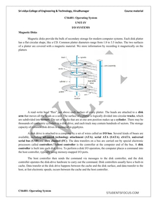
- 1. Sri vidya College of Engineering & Technology, Virudhunagar Course material CS6401- Operating System CS6401- Operating System UNIT-IV I/O SYSTEMS Magnetic Disks Magnetic disks provide the bulk of secondary storage for modern computer systems. Each disk platter has a flat circular shape, like a CD. Common platter diameters range from 1.8 to 3.5 inches. The two surfaces of a platter are covered with a magnetic material. We store information by recording it magnetically on the platters A read–write head “flies” just above each surface of every platter. The heads are attached to a disk arm that moves all the heads as a unit. The surface of a platter is logically divided into circular tracks, which are subdivided into sectors. The set of tracks that are at one arm position makes up a cylinder. There may be thousands of concentric cylinders in a disk drive, and each track may contain hundreds of sectors. The storage capacity of common disk drives is measured in gigabytes. A disk drive is attached to a computer by a set of wires called an I/O bus. Several kinds of buses are available, including advanced technology attachment (ATA), serial ATA (SATA), eSATA, universal serial bus (USB),and fibre channel (FC). The data transfers on a bus are carried out by special electronic processors called controllers.Thehost controller is the controller at the computer end of the bus. A disk controller is built into each disk drive. To perform a disk I/O operation, the computer places a command into the host controller, typically using memory-mapped I/O ports. The host controller then sends the command via messages to the disk controller, and the disk controller operates the disk-drive hardware to carry out the command. Disk controllers usually have a built-in cache. Data transfer at the disk drive happens between the cache and the disk surface, and data transfer to the host, at fast electronic speeds, occurs between the cache and the host controller. STUDENTSFOCUS.COM
- 2. Sri vidya College of Engineering & Technology, Virudhunagar Course material CS6401- Operating System Solid-State Disks Sometimes old technologies are used in new ways as economics change or the technologies evolve. An example is the growing importance of solid-state disks,or SSDs. Simply described, an SSD is nonvolatile memory that is used like a hard drive. There are many variations of this technology, from DRAM with a battery to allow it to maintain its state in a power failure through flash-memory technologies like single-level cell (SLC) and multilevel cell (MLC) chips. SSDs have the same characteristics as traditional hard disks but can be more reliable because they have no moving parts and faster because they have no seek time or latency. In addition, they consume less power. However, they are more expensive per megabyte than traditional hard disks, have less capacity than the larger hard disks, and may have shorter life spans than hard disks, so their uses are somewhat limited. One use for SSDs is in storage arrays, where they hold file-system metadata that require high performance. SSDs are also used in some laptop computers to make them smaller, faster, and more energy-efficient. Because SSDs can be much faster than magnetic disk drives, standard bus interfaces can cause a major limit on throughput. Magnetic Tapes Magnetic tape was used as an early secondary-storage medium. Although it is relatively permanent and can hold large quantities of data, its access time is slow compared with that of main memory and magnetic disk. In addition, random access to magnetic tape is about a thousand times slower than random access to magnetic disk, so tapes are not very useful for secondary storage. Tapes are used mainly for backup, for storage of infrequently used information, and as a medium for transferring information from one system to another. A tape is kept in a spool and is wound or rewound past a read–write head. Moving to the correct spot on a tape can take minutes, but once positioned, tape drives can write data at speeds comparable to disk drives. Tape capacities vary greatly, depending on the particular kind of tape drive, with current capacities exceeding several terabytes. Some tapes have built-in compression that can more than double the effective storage. Tapes and their drivers are usually categorized by width, including 4, 8, and 19 millimetres and 1/4 and 1/2 inch. Some are named according to technology, such as LTO-5 and SDLT. Disk Scheduling and Management One of the responsibilities of the operating system is to use the hardware efficiently. For the disk drives, 1. A fast access time and 2. High disk bandwidth. The access time has two major components; The seek time is the time for the disk arm to move the heads to the cylinder containing the desired sector. The rotational latency is the additional time waiting for the disk to rotate the desired sector to the disk head. The disk b a n d w i d t his the total number of bytes transferred, divided by the total time between the first request for service and the completion of the last transfer. STUDENTSFOCUS.COM
- 3. Sri vidya College of Engineering & Technology, Virudhunagar Course material CS6401- Operating System One of the responsibilities of the operating system is to use the hardware efficiently. For the disk drives, 1. A fast access time and 2. High disk bandwidth. The access time has two major components; The seek time is the time for the disk arm to move the heads to the cylinder containing the desired sector. The rotational latency is the additional time waiting for the disk to rotate the desired sector to the disk head. The disk bandwidth is the total number of bytes transferred, divided by the total time between the first request for service and the completion of the last transfer. We can improve both the access time and the bandwidth by disk scheduling. Disk scheduling: Servicing of disk I/O requests in a good order. 1. FCFS Scheduling: The simplest form of disk scheduling is, of course, the first-come, first-served (FCFS) algorithm. This algorithm is intrinsically fair, but it generally does not provide the fastest service. Consider, for example, a disk queue with requests for I/O to blocks on cylinders I/O to blocks on cylinders 98, 183, 37, 122, 14, 124, 65, 67, If the disk head is initially at cylinder 53, it will first move from 53 to 98, then to 183, 37, 122, 14, 124, 65, and finally to 67, for a total head movement of 640 cylinders. The wild swing from 122 to 14 and then back to 124 illustrates the problem with this schedule. If the requests for cylinders 37 and 14 could be serviced together, before or after the requests for 122 and 124, the total head movement could be decreased substantially, and performance could be thereby improved. STUDENTSFOCUS.COM
- 4. Sri vidya College of Engineering & Technology, Virudhunagar Course material CS6401- Operating System 2. SSTF (shortest-seek-time-first)Scheduling Service all the requests close to the current head position, before moving the head far away to service other requests. That is selects the request with the minimum seek time from the current head position. Total head movement = 236 cylinders 3. SCAN Scheduling The disk head starts at one end of the disk, and moves toward the other end, servicing requests as it reaches each cylinder, until it gets to the other end of the disk. At the other end, the direction of head movement is reversed, and servicing continues. The head continuously scans back and forth across the disk. 4. C-SCAN Scheduling Variant of SCAN designed to provide a more uniform wait time. It moves the head from one end of the disk to the other, servicing requests along the way. When the head reaches the other end, however, it immediately returns to the beginning of the disk, without servicing any requests on the return trip. STUDENTSFOCUS.COM
- 5. Sri vidya College of Engineering & Technology, Virudhunagar Course material CS6401- Operating System 5. LOOK Scheduling Both SCAN and C-SCAN move the disk arm across the full width of the disk. In this, the arm goes only as far as the final request in each direction. Then, it reverses direction immediately, without going all the way to the end of the disk. Disk Management 1. Disk Formatting: Before a disk can store data, the sector is divided into various partitions. This process is called low- level formatting or physical formatting. It fills the disk with a special data structure for each sector. The data structure for a sector consists of Header, Data area (usually 512 bytes in size), and Trailer. STUDENTSFOCUS.COM
- 6. Sri vidya College of Engineering & Technology, Virudhunagar Course material CS6401- Operating System The header and trailer contain information used by the disk controller, such as a sector number and an error-correcting code (ECC). This formatting enables the manufacturer to 1. Test the disk and 2. To initialize the mapping from logical block numbers To use a disk to hold files, the operating system still needs to record its own data structures on the disk. It does so in two steps. (a) The first step is Partition the disk into one or more groups of cylinders. Among the partitions, one partition can hold a copy of the OS‘s executable code, while another holds user files. (b) The second step is logical formatting .The operating system stores the initial file-system data structures onto the disk. These data structures may include maps of free and allocated space and an initial empty directory. 2. Boot Block: For a computer to start running-for instance, when it is powered up or rebooted-it needs to have an initial program to run. This initial program is called bootstrap program & it should be simple. It initializes all aspects of the system, from CPU registers to device controllers and the contents of main memory, and then starts the operating system. To do its job, the bootstrap program 1. Finds the operating system kernel on disk, 2. Loads that kernel into memory, and 3. Jumps to an initial address to begin the operating-system execution. The bootstrap is stored in read-only memory (ROM). Advantages: 1. ROM needs no initialization. 2. It is at a fixed location that the processor can start executing when powered up or reset. 3. It cannot be infected by a computer virus. Since, ROM is read only. The full bootstrap program is stored in a partition called the boot blocks, at a fixed location on the disk. A disk that has a boot partition is called a boot disk or system disk. The code in the boot ROM instructs the disk controller to read the boot blocks into memory and then starts executing that code. Bootstrap loader: load the entire operating system from a non-fixed location on disk, and to start the operating system running. 3. Bad Blocks: The disk with defected sector is called as bad block. Depending on the disk and controller in use, these blocks are handled in a variety of ways; STUDENTSFOCUS.COM
- 7. Sri vidya College of Engineering & Technology, Virudhunagar Course material CS6401- Operating System Method 1: “Handled manually‖ If blocks go bad during normal operation, a special program must be run manually to search for the bad blocks and to lock them away as before. Data that resided on the bad blocks usually are lost. Method 2: “sector sparing or forwarding” The controller maintains a list of bad blocks on the disk. Then the controller can be told to replace each bad sector logically with one of the spare sectors. This scheme is known as sector sparing or forwarding. A typical bad-sector transaction might be as follows: 1. The operating system tries to read logical block 87. 2. The controller calculates the ECC and finds that the sector is bad. 3. It reports this finding to the operating system. 4. The next time that the system is rebooted, a special command is run to tell the controller to replace the bad sector with a spare. 5. After that, whenever the system requests logical block 87, the request is translated into the replacement sector's address by the controller. Method 3: “sector slipping” For an example, suppose that logical block 17 becomes defective, and the first available spare follows sector 202. Then, sector slipping would remap all the sectors from 17 to 202, moving them all down one spot. That is, sector 202 would be copied into the spare, then sector 201 into 202, and then 200 into 201, and so on, until sector 18 is copied into sector 19. Slipping the sectors in this way frees up the space of sector 18, so sector 17 can be mapped to it. File System Storage-File Concepts File Concept A file is a named collection of related information that is recorded on secondary storage. From a user’s perspective, a file is the smallest allotment of logical secondary storage; that is, data cannot be written to secondary storage unless they are within a file. Examples of files: A text file is a sequence of characters organized into lines (and possibly pages). A source file is a sequence of subroutines and functions, each of which is further organized as declarations followed by executable statements. An object file is a sequence of bytes organized into blocks understandable by the system’s linker. An executable file is a series of code sections that the loader can bring into memory and execute. File Attributes Name: The symbolic file name is the only information kept in human readable form. Identifier: This unique tag, usually a number identifies the file within the file system. It is the non-human readable name for the file. Type: This information is needed for those systems that support different types. STUDENTSFOCUS.COM
- 8. Sri vidya College of Engineering & Technology, Virudhunagar Course material CS6401- Operating System Location: This information is a pointer to a device and to the location of the file on that device. Size: The current size of the file (in bytes, words or blocks)and possibly the maximum allowed size are included in this attribute. Protection: Access-control information determines who can do reading, writing, executing and so on. Time, date and user identification: This information may be kept for creation, last modification and last use. These data can be useful for protection, security and usage monitoring. File Operations Creating a file Writing a file Reading a file Repositioning within a file Deleting a file Truncating a file Access Methods 1. Sequential Access a. The simplest access method is sequential access. Information in the file is processed in order, one record after the other. This mode of access is by far the most common; for example, editors and compilers usually access files in this fashion. The bulk of the operations on a file is reads and writes. A read operation reads the next portion of the file and automatically advances a file pointer, which tracks the I/O location. Similarly, a write appends to the end of the file and advances to the end of the newly written material (the new end of file). Such a file can be reset to the beginning and, on some systems, a program may be able to skip forward or back ward n records, for some integer n-perhaps only for n=1. Sequential access is based on a tape model of a file, and works as well on sequential-access devices as it does on random – access ones. 2. Direct Access Another method is direct access (or relative access). A file is made up of fixed length logical records that allow programs to read and write records rapidly in no particular order. The direct- access methods is based on a disk model of a file, since disks allow random access to any file block. For direct access, the file is viewed as a numbered sequence of blocks or records. A direct-access file allows arbitrary blocks to be read or written. Thus, we may read block 14, then read block 53, and then write block7. There are no restrictions on the order of reading or writing for a direct-access file. Direct – access files are of great use for immediate access to large amounts of information. Database is often of this type. When a query concerning a particular subject arrives, we compute which block contains the answer, and then read that block directly to provide the desired information. STUDENTSFOCUS.COM
- 9. Sri vidya College of Engineering & Technology, Virudhunagar Course material CS6401- Operating System Directory and Disk Structure There are five directory structures. They are 1. Single-level directory 2. Two-level directory 3. Tree-Structured directory 4. Acyclic Graph directory 5. General Graph directory 1. Single – Level Directory The simplest directory structure is the single- level directory. All files are contained in the same directory. Disadvantage: When the number of files increases or when the system has more than one user, since all files are in the same directory, they must have unique names. 2. Two – Level Directory In the two level directory structures, each user has her own user file directory (UFD). When a user job starts or a user logs in, the system’s master file directory (MFD) is searched. The MFD is indexed by user name or account number, and each entry points to the UFD for that user. When a user refers to a particular file, only his own UFD is searched. Thus, different users may have files with the same name. Although the two – level directory structure solves the name-collision problem Disadvantage: Users cannot create their own sub-directories. 3. Tree – Structured Directory A tree is the most common directory structure. The tree has a root directory. Every file in the system has a unique path name. A path name is the path from the root, through all the subdirectories to a specified file. A directory (or sub directory) contains a set of files or sub directories. A directory is simply another file. But it is treated in a special way. All directories have the same internal format. STUDENTSFOCUS.COM
- 10. Sri vidya College of Engineering & Technology, Virudhunagar Course material CS6401- Operating System One bit in each directory entry defines the entry as a file (0) or as a subdirectory (1). Special system calls are used to create and delete directories. Path names can be of two types: absolute path names or relative path names. An absolute path name begins at the root and follows a path down to the specified file, giving the directory names on the path. A relative path name defines a path from the current directory. 4. Acyclic Graph Directory. An acyclic graph is a graph with no cycles. To implement shared files and subdirectories this directory structure is used. An acyclic – graph directory structure is more flexible than is a simple tree structure, but it is also more complex. In a system where sharing is implemented by symbolic link, this situation is somewhat easier to handle. The deletion of a link does not need to affect the original file; only the link is removed. Another approach to deletion is to preserve the file until all references to it are deleted. To implement this approach, we must have some mechanism for determining that the last reference to the file has been deleted. Sharing and Protection File Sharing STUDENTSFOCUS.COM
- 11. Sri vidya College of Engineering & Technology, Virudhunagar Course material CS6401- Operating System 1. Multiple Users: When an operating system accommodates multiple users, the issues of file sharing, file naming and file protection become preeminent. The system either can allow user to access the file of other users by default, or it may require that a user specifically grant access to the files. These are the issues of access control and protection. To implementing sharing and protection, the system must maintain more file and directory attributes than a on a single-user system. The owner is the user who may change attributes, grand access, and has the most control over the file or directory. The group attribute of a file is used to define a subset of users who may share access to the file. Most systems implement owner attributes by managing a list of user names and associated user identifiers (user Ids). When a user logs in to the system, the authentication stage determines the appropriate user ID for the user. That user ID is associated with all of user’s processes and threads. When they need to be user readable, they are translated, back to the user name via the user name list. Likewise, group functionality can be implemented as a system wide list of group names and group identifiers. Every user can be in one or more groups, depending upon operating system design decisions. The user’s group Ids is also included in every associated process and thread. 2. Remote File System: Networks allowed communications between remote computers. Networking allows the sharing or resource spread within a campus or even around the world. User manually transfer files between machines via programs like ftp. A distributed file system (DFS) in which remote directories is visible from the local machine. The World Wide Web: A browser is needed to gain access to the remote file and separate operations (essentially a wrapper for ftp) are used to transfer files. a) The client-server Model: Remote file systems allow a computer to a mount one or more file systems from one or more remote machines. A server can serve multiple clients, and a client can use multiple servers, depending on the implementation details of a given client –server facility. Client identification is more difficult. Clients can be specified by their network name or other identifier, such as IP address, but these can be spoofed (or imitate). An unauthorized client can spoof the server into deciding that it is authorized, and the unauthorized client could be allowed access. b) Distributed Information systems: Distributed information systems, also known as distributed naming service, have been devised to provide a unified access to the information needed for remote computing. Domain name system (DNS) provides host-name-to-network address translations for their entire Internet (including the World Wide Web). Before DNS was invented and became widespread, files containing the same information were sent via e-mail of ftp between all networked hosts. c) Failure Modes: Redundant arrays of inexpensive disks (RAID) can prevent the loss of a disk from resulting in the loss of data. STUDENTSFOCUS.COM
- 12. Sri vidya College of Engineering & Technology, Virudhunagar Course material CS6401- Operating System Remote file system has more failure modes. By nature of the complexity of networking system and the required interactions between remote machines, many more problems can interfere with the proper operation of remote file systems. d) Consistency Semantics: It is characterization of the system that specifies the semantics of multiple users accessing a shared file simultaneously. These semantics should specify when modifications of data by one user are observable by other users. The semantics are typically implemented as code with the file system. A series of file accesses (that is reads and writes) attempted by a user to the same file is always enclosed between the open and close operations. The series of access between the open and close operations is a file session. (i) UNIX Semantics: The UNIX file system uses the following consistency semantics: 1. Writes to an open file by a user are visible immediately to other users that have this file open at the same time. 2. One mode of sharing allows users to share the pointer of current location into the file. Thus, the advancing of the pointer by one user affects all sharing users. (ii) Session Semantics: The Andrew file system (AFS) uses the following consistency semantics: 1. Writes to an open file by a user are not visible immediately to other users that have the same file open simultaneously. 2. Once a file is closed, the changes made to it are visible only in sessions starting later. Already open instances of the file do not reflect this change. (iii) Immutable –shared File Semantics: Once a file is declared as shared by its creator, it cannot be modified. An immutable file has two key properties: Its name may not be reused and its contents may not be altered. File Protection (i) Need for file protection. When information is kept in a computer system, we want to keep it safe from physical damage (reliability) and improper access (protection). Reliability is generally provided by duplicate copies of files. Many computers have systems programs that automatically (or though computer-operator intervention) copy disk files to tape at regular intervals (once per day or week or month) to maintain a copy should a file system be accidentally destroyed. File systems can be damaged by hardware problems (such as errors in reading or writing), power surges or failures, head crashes, dirt, temperature extremes, and vandalism. Files may be deleted accidentally. Bugs in the file-system software can also cause file contents to be lost. Protection can be provided in many ways. For a small single-user system, we might provide protection by physically removing the floppy disks and locking them in a desk drawer or file cabinet. In a multi-user system, however, other mechanisms are needed. (ii) Types of Access Complete protection is provided by prohibiting access. Free access is provided with no protection. Both approaches are too extreme for general use. STUDENTSFOCUS.COM
- 13. Sri vidya College of Engineering & Technology, Virudhunagar Course material CS6401- Operating System What is needed is controlled access. Protection mechanisms provide controlled access by limiting the types of file access that can be made. Access is permitted or denied depending on several factors, one of which is the type of access requested. Several different types of operations may be controlled: 1. Read: Read from the file. 2. Write: Write or rewrite the file. 3. Execute: Load the file into memory and execute it. 4. Append: Write new information at the end of the file. 5. Delete: Delete the file and free its space for possible reuse. 6. List: List the name and attributes of the file. (iii) Access Control Associate with each file and directory an access-control list (ACL) specifying the user name and the types of access allowed for each user. When a user requests access to a particular file, the operating system checks the access list associated with that file. If that user is listed for the requested access, the access is allowed. Otherwise, a protection violation occurs and the user job is denied access to the file. This technique has two undesirable consequences: Constructing such a list may be a tedious and unrewarding task, especially if we do not know in advance the list of users in the system. The directory entry, previously of fixed size, now needs to be of variable size, resulting in more complicated space management. To condense the length of the access control list, many systems recognize three classifications of users in connection with each file: Owner: The user who created the file is the owner. Group: A set of users who are sharing the file and need similar access is a group, or work group. Universe: All other users in the system constitute the universe. File System Implementation- File System Structure Disk provide the bulk of secondary storage on which a file system is maintained. Characteristics of a disk: 1. They can be rewritten in place, it is possible to read a block from the disk, to modify the block and to write it back into the same place. 2. They can access directly any given block of information to the disk. To produce an efficient and convenient access to the disk, the operating system imposes one or more file system to allow the data to be stored, located and retrieved easily. The file system itself is generally composed of many different levels. Each level in the design uses the features of lower level to create new features for use by higher levels. Layered File System The I/O control consists of device drivers and interrupt handlers to transfer information between the main memory and the disk system . The basic file system needs only to issue generic commands to the appropriate device driver to read and write physical blocks on the disk. Each physical block is identified by its numeric disk address (for example, drive –1, cylinder 73, track 2, sector 10) STUDENTSFOCUS.COM
- 14. Sri vidya College of Engineering & Technology, Virudhunagar Course material CS6401- Operating System Directory Implementation 1. Linear List The simplest method of implementing a directory is to use a linear list of file names with pointer to the data blocks. A linear list of directory entries requires a linear search to find a particular entry. This method is simple to program but time- consuming to execute. To create a new file, we must first search the but time – consuming to execute. The real disadvantage of a linear list of directory entries is the linear search to find a file. 2. Hash Table In this method, a linear list stores the directory entries, but a hash data structure is also used. The hash table takes a value computed from the file name and returns a pointer to the file name in the linear list. Therefore, it can greatly decrease the directory search time. Insertion and deleting are also fairly straight forward, although some provision must be made for collisions – situation where two file names hash to the same location. The major difficulties with a hash table are its generally fixed size and the dependence of the hash function on that size. Allocation Methods The main problem is how to allocate space to these files so that disk space is utilized effectively and files can be accessed quickly. There are three major methods of allocating disk space: 1. Contiguous Allocation 2. Linked Allocation 3. Indexed Allocation 1. Contiguous Allocation The contiguous – allocation method requires each file to occupy a set of contiguous blocks on the disk. Contiguous allocation of a file is defined by the disk address and length (in block units) of the first block. If the file is n blocks long and starts at location b, then it occupies blocks b,. b+1, b+2,….,b+n-1. STUDENTSFOCUS.COM
- 15. Sri vidya College of Engineering & Technology, Virudhunagar Course material CS6401- Operating System The directory entry for each file indicates the address of the starting block and the length of the area allocated for this file. Disadvantages: 1. Finding space for a new file. The contiguous disk space-allocation problem suffer from the problem of external fragmentation. As file are allocated and deleted, the free disk space is broken into chunks. It becomes a problem when the largest contiguous chunk is insufficient for a request; storage is fragmented into a number of holes, no one of which is large enough to store the data. 2. Determining how much space is needed for a file. When the file is created, the total amount of space it will need must be found an allocated how does the creator know the size of the file to be created? If we allocate too little space to a file, we may find that file cannot be extended. The other possibility is to find a larger hole, copy the contents of the file to the new space, and release the previous space. This series of actions may be repeated as long as space exists, although it can be time – consuming. However, in this case, the user never needs to be informed explicitly about what is happening ; the system continues despite the problem, although more and more slowly. Even if the total amount of space needed for a file is known in advance pre-allocation may be inefficient. A file that grows slowly over a long period (months or years) must be allocated enough space for its final size, even though much of that space may be unused for a long time the file, therefore has a large amount of internal fragmentation. To overcome these disadvantages: Use a modified contiguous allocation scheme, in which a contiguous chunk of space called as an extent is allocated initially and then, when that amount is not large enough another chunk of contiguous space an extent is added to the initial allocation. Internal fragmentation can still be a problem if the extents are too large, and external fragmentation can be a problem as extents of varying sizes are allocated and deallocated. 2. Linked Allocation Linked allocation solves all problems of contiguous allocation. With linked allocation, each file is a linked list of disk blocks, the disk blocks may be scattered any where on the disk. The directory contains a pointer to the first and last blocks of the file. For example, a file of five blocks might start at block 9, continue at block 16, then block 1, block 10, and finally bock 25. Each block contains a pointer to the next block. These pointers are not made available to the user. There is no external fragmentation with linked allocation, and any free block on the free space list can be used to satisfy a request. The size of a file does not need to the declared when that file is created. A file can continue to grow as long as free blocks are available consequently, it is never necessary to compacts disk space. STUDENTSFOCUS.COM
- 16. Sri vidya College of Engineering & Technology, Virudhunagar Course material CS6401- Operating System Disadvantages: 1. Used effectively only for sequential access files. To find the ith block of a file, we must start at the beginning of that file, and follow the pointers until we get to the ith block. Each aces to a pointer requires a disk read, and sometimes a disk seek consequently, it is inefficient to support a direct- access capability for linked allocation files. 2. Space required for the pointers If a pointer requires 4 bytes out of a 512-byte block, then 0.78 percent of the disk is being used for pointers, rather than for information. Solution to this problem is to collect blocks into multiples, called clusters, and to allocate the clusters rather than blocks. For instance, the file system may define a clusters as 4 blocks, and operate on the disk in only cluster units. 3. Reliability Since the files are linked together by pointers scattered all over the disk hardware failure might result in picking up the wrong pointer. This error could result in linking into the free- space list or into another file. Partial solution are to use doubly linked lists or to store the file names in a relative block number in each block; however, these schemes require even more over head for each file. File Allocation Table(FAT) An important variation on the linked allocation method is the use of a file allocation table(FAT). This simple but efficient method of disk- space allocation is used by the MS-DOS and OS/2 operating systems. A section of disk at beginning of each partition is set aside to contain the table. The table has entry for each disk block, and is indexed by block number. The FAT is much as is a linked list. The directory entry contains the block number the first block of the file. The table entry indexed by that block number contains the block number of the next block in the file. This chain continues until the last block which has a special end – of – file value as the table entry. Unused blocks are indicated by a 0 table value. Allocating a new block file is a simple matter of finding the first 0 – valued table entry, and replacing the previous end of file value with the address of the new block. The 0 is replaced with the end – of – file value, an illustrative example is the FAT structure for a file consisting of disk blocks 217,618, and 339. 3. Indexed Allocation Linked allocation solves the external – fragmentation and size- declaration problems of contiguous allocation. Linked allocation cannot support efficient direct access, since the pointers to the blocks are scattered with the blocks themselves all over the disk and need to be retrieved in order. Indexed allocation solves this problem by bringing all the pointers together into one location: the index block. Each file has its own index block, which is an array of disk – block addresses. The ith entry in the index block points to the ith block of the file. The directory contains the address of the index block . To read the ith block, we use the pointer in the ith index – block entry to find and read the desired block this scheme is similar to the paging scheme . STUDENTSFOCUS.COM
- 17. Sri vidya College of Engineering & Technology, Virudhunagar Course material CS6401- Operating System When the file is created, all pointers in the pointers in the index block are set to nil. when the ith block is first written, a block is obtained from the free space manager, and its address is put in the ith index – block entry. Indexed allocation supports direct access, without suffering from external fragmentation, because any free block on the disk may satisfy a request for more space. Disadvantages 1.Pointer Overhead Indexed allocation does suffer from wasted space. The pointer over head of the index block is generally greater than the pointer over head of linked allocation. 2. Size of Index block If the index block is too small, however, it will not be able to hold enough pointers for a large file, and a mechanism will have to be available to deal with this issue: Linked Scheme: An index block is normally one disk block. Thus, it can be read and written directly by itself. To allow for large files, we may link together several index blocks. Multilevel index: A variant of the linked representation is to use a first level index block to point to a set of second – level index blocks. Combined scheme: o Another alternative, used in the UFS, is to keep the first, say, 15 pointers of the index block in the file’s inode. o The first 12 of these pointers point to direct blocks; that is for small ( no more than 12 blocks) files do not need a separate index block o The next pointer is the address of a single indirect block. The single indirect block is an index block, containing not data, but rather the addresses of blocks that do contain data. o Then there is a double indirect block pointer, which contains the address of a block that contain pointers to the actual data blocks. The last pointer would contain pointers to the actual data blocks. o The last pointer would contain the address of a triple indirect block. STUDENTSFOCUS.COM
- 18. Sri vidya College of Engineering & Technology, Virudhunagar Course material CS6401- Operating System Free-space Management Since disk space is limited, we need to reuse the space from deleted files for new files, if possible. To keep track of free disk space, the system maintains a free-space list. The free-space list records all free disk blocks – those not allocated to some file or directory. To create a file, we search the free-space list for the required amount of space, and allocate that space to the new file. This space is then removed from the free-space list. When a file is deleted, its disk space is added to the free-space list. 1. Bit Vector The free-space list is implemented as a bit map or bit vector. Each block is represented by 1 bit. If the block is free, the bit is 1; if the block is allocated, the bit is 0. For example, consider a disk where block 2,3,4,5,8,9,10,11,12,13,17,18,25,26 and 27 are free, and the rest of the block are allocated. The free space bit map would be 001111001111110001100000011100000 … The main advantage of this approach is its relatively simplicity and efficiency in finding the first free block, or n consecutive free blocks on the disk. 2. Linked List Another approach to free-space management is to link together all the free disk blocks, keeping a pointer to the first free block in a special location on the disk and caching it in memory. This first block contains a pointer to the next free disk block, and so on. In our example, we would keep a pointer to block 2, as the first free block. Block 2 would contain a pointer to block 3, which would point to block 4, which would point to block 5, which would point to block 8, and so on. However, this scheme is not efficient; to traverse the list, we must read each block, which requires substantial I/O time. The FAT method incorporates free-block accounting data structure. No separate method is needed. STUDENTSFOCUS.COM
- 19. Sri vidya College of Engineering & Technology, Virudhunagar Course material CS6401- Operating System 3. Grouping A modification of the free-list approach is to store the addresses of n free blocks in the first free block. The first n-1 of these blocks are actually free. The last block contains the addresses of another n free blocks, and so on. The importance of this implementation is that the addresses of a large number of free blocks can be found quickly. 4. Counting We can keep the address of the first free block and the number n of free contiguous blocks that follow the first block. Each entry in the free-space list then consists of a disk address and a count. Although each entry requires more space than would a simple disk address, the overall list will be shorter, as long as the count is generally greater than 1. I/O Systems I/O Hardware The role of the operating system in computer I/O is to manage and control I/O operations and I/O devices. A device communicates with a computer system by sending signals over a cable or even through the air. Port: The device communicates with the machine via a connection point (or port), for example, a serial port. Bus: If one or more devices use a common set of wires, the connection is called a bus. Daisy chain: Device ‗A‘ has a cable that plugs into device ‗B‘, and device ‗B‘ has a cable that plugs into device ‗C‘, and device ‗C‘ plugs into a port on the computer, this arrangement is called a daisy chain. A daisy chain usually operates as a bus. PC bus structure: A PCI bus that connects the processor-memory subsystem to the fast devices, and an expansion bus that connects relatively slow devices such as the keyboard and serial and parallel ports. In the upper-right portion of the figure, four disks are connected together on a SCSI bus plugged into a SCSI controller. A controller or host adapter is a collection of electronics that can operate a port, a bus, or a device. A serial-port controller is a simple device controller. It is a single chip in the computer that controls the signals on the wires of a serial port. By contrast, a SCSI bus controller is not simple. Because the SCSI STUDENTSFOCUS.COM
- 20. Sri vidya College of Engineering & Technology, Virudhunagar Course material CS6401- Operating System protocol is complex, the SCSI bus controller is often implemented as a separate circuit board. It typically contains a processor, microcode, and some private memory. Some devices have their own built-in controllers. How can the processor give commands and data to a controller to accomplish an I/O transfer? o Direct I/O instructions o Memory-mapped I/O Direct I/O instructions Use special I/O instructions that specify the transfer of a byte or word to an I/O port address. The I/O instruction triggers bus lines to select the proper device and to move bits into or out of a device register Memory-mapped I/O The device-control registers are mapped into the address space of the processor. The CPU executes I/O requests using the standard data-transfer instructions to read and write the device-control registers. An I/O port typically consists of four registers: status, control, data-in, and data-out registers. Status register Read by the host to indicate states such as whether the current command has completed, whether a byte is available to be read from the data-in register, and whether there has been a device error. Control register Written by the host to start a command or to change the mode of a device. data-in register Read by the host to get input data-out register Written by the host to send output Polling Interaction between the host and a controller The controller sets the busy bit when it is busy working, and clears the busy bit when it is ready to accept the next command. The host sets the command ready bit when a command is available for the controller to execute. STUDENTSFOCUS.COM
- 21. Sri vidya College of Engineering & Technology, Virudhunagar Course material CS6401- Operating System Coordination between the host & the controller is done by handshaking as follows: 1. The host repeatedly reads the busy bit until that bit becomes clear. 2. The host sets the write bit in the command register and writes a byte into the data-out register. 3. The host sets the command-ready bit. 4. When the controller notices that the command-ready bit is set, it sets the busy bit. 5. The controller reads the command register and sees the write command. It reads the data-out register to get the byte, and does the I/O to the device. 6. The controller clears the command-ready bit, clears the error bit in the status register to indicate that the device I/O succeeded, and clears the busy bit to indicate that it is finished. In step 1, the host is ―busy-waiting or polling‖: It is in a loop, reading the status register over and over until the busy bit becomes clear. Interrupts The CPU hardware has a wire called the ―interrupt-request line‖. The basic interrupt mechanism works as follows; 1. Device controller raises an interrupt by asserting a signal on the interrupt request line. 2. The CPU catches the interrupt and dispatches to the interrupt handler and 3. The handler clears the interrupt by servicing the device. Two interrupt request lines: 1. Nonmaskable interrupt: which is reserved for events such as unrecoverable memory errors? 2. Maskable interrupt: Used by device controllers to request service Application I/O Interface I/O system calls encapsulate device behaviors in generic classes Device-driver layer hides differences among I/O controllers from kernel STUDENTSFOCUS.COM
- 22. Sri vidya College of Engineering & Technology, Virudhunagar Course material CS6401- Operating System Devices vary in many dimensions 1. Character-stream or block 2. Sequential or random-access 3. Sharable or dedicated 4. Speed of operation 5. read-write, read only, or write only Types Description Example Character-stream or block A character-stream device transfers bytes one by one, whereas a block device transfers a block of bytes as a unit. Terminal, Disk Sequential or random-access A sequential device transfers data in a fixed order determined by the device, whereas the user of a random-access device can instruct the device to seek to any of the available data storage locations. Modem, CD-ROM Sharable or dedicated A sharable device can be used concurrently by several processes or threads; a dedicated device cannot. Tape, Keyboard Speed of operation Latency, seek time, transfer rate, delay between operations read-write, read only, or write only Some devices perform both input and output, but others support only one data direction. CD-ROM, Graphics controller, Disk Block and Character Devices Block-device: The block-device interface captures all the aspects necessary for accessing disk drives and other block-oriented devices. The device should understand the commands such as read () & write (), and if it is a random access device, it has a seek() command to specify which block to transfer next. Applications normally access such a device through a file-system interface. The OS itself, and special applications such as database-management systems, may prefer to access a block device as a simple linear array of blocks. This mode of access is sometimes called raw I/O. Memory-mapped file access can be layered on top of block-device drivers. Rather than offering read and write operations, a memory-mapped interface provides access to disk storage via an array of bytes in main memory. Character Devices: A keyboard is an example of a device that is accessed through a character stream interface. The basic system calls in this interface enable an application to get() or put() one character. On top of this interface, libraries can be built that offer line-at-a-time access, with buffering and editing services. (+) This style of access is convenient for input devices where it produce input "spontaneously". (+) This access style is also good for output devices such as printers or audio boards, which naturally fit the concept of a linear stream of bytes. Network Devices Because the performance and addressing characteristics of network I/O differ significantly from those of disk I/O, most operating systems provide a network I/O interface that is different from the read0 -write() - seek() interface used for disks. STUDENTSFOCUS.COM
- 23. Sri vidya College of Engineering & Technology, Virudhunagar Course material CS6401- Operating System Windows NT provides one interface to the network interface card, and a second interface to the network protocols. In UNIX, we find half-duplex pipes, full-duplex FIFOs, full-duplex STREAMS, message queues and sockets. Clocks and Timers Most computers have hardware clocks and timers that provide three basic functions: 1. Give the current time 2. Give the elapsed time 3. Set a timer to trigger operation X at time T These functions are used by the operating system & also by time sensitive applications. Programmable interval timer: The hardware to measure elapsed time and to trigger operations is called a programmable interval timer. It can be set to wait a certain amount of time and then to generate an interrupt. To generate periodic interrupts, it can be set to do this operation once or to repeat. Blocking and Non-blocking I/O (or) synchronous & asynchronous: Blocking I/O: When an application issues a blocking system call; Theexecution of the application is suspended. The application is moved from the operating system's run queue to a wait queue. After the system call completes, the application is moved back to the run queue, where it is eligible to resume execution, at which time it will receive the values returned by the system call. Non-blocking I/O: Some user-level processes need non-blocking I/O. Examples: 1. User interface that receives keyboard and mouse input while processing and displaying data on the screen. 2. Video application that reads frames from a file on disk while simultaneously decompressing and displaying the output on the display. Kernel I/O Subsystem Kernels provide many services related to I/O. Oneway that the I/O subsystem improves the efficiency of the computer is by scheduling I/O operations. Another way is by using storage space in main memory or on disk, via techniques called buffering, caching, and spooling. I/O Scheduling: To determine a good order in which to execute the set of I/O requests. Uses: a) It can improve overall system performance, b) It can share device access fairly among processes, and c) It can reduce the average waiting time for 1/0 to complete. Implementation: OS developers implement scheduling by maintaining a ―queue of requestsǁ for each device. 1. When an application issues a blocking I/O system call, 2. The request is placed on the queue for that device. STUDENTSFOCUS.COM
- 24. Sri vidya College of Engineering & Technology, Virudhunagar Course material CS6401- Operating System 3. The I/O scheduler rearranges the order of the queue to improve the overall system efficiency and the average response time experienced by applications. Buffering: Buffer: A memory area that stores data while they are transferred between two devices or between a device and an application. Reasons for buffering: a) To cope with a speed mismatch between the producer and consumer of a data stream. b) To adapt between devices that have different data-transfer sizes. c) To support copy semantics for application I/O. Copy semantics: Suppose that an application has a buffer of data that it wishes to write to disk. It calls the write () system call, providing a pointer to the buffer and an integer specifying the number of bytes to write. After the system call returns, what happens if the application changes the contents of the buffer? With copy semantics, the version of the data written to disk is guaranteed to be the version at the time of the application system call, independent of any subsequent changes in the application's buffer. A simple way that the operating system can guarantee copy semantics is for the write() system call to copy the application data into a kernel buffer before returning control to the application. The disk write is performed from the kernel buffer, so that subsequent changes to the application buffer have no effect. Caching A cache is a region of fast memory that holds copies of data. Access to the cached copy is more efficient than access to the original Cache vs buffer: A buffer may hold the only existing copy of a data item, whereas a cache just holds a copy on faster storage of an item that resides elsewhere. When the kernel receives a file I/O request, 1. The kernel first accesses the buffer cache to see whether that region of the file is already available in main memory. 2. If so, a physical disk I/O can be avoided or deferred. Also, disk writes are accumulated in the buffer cache for several seconds, so that large transfers are gathered to allow efficient write schedules. Spooling and Device Reservation: Spool: A buffer that holds output for a device, such as a printer, that cannot accept interleaved data streams. A printer can serve only one job at a time, several applications may wish to print their output concurrently, without having their output mixed together The os provides a control interface that enables users and system administrators ; a) To display the queue, b) To remove unwanted jobs before those jobs print, c) To suspend printing while the printer is serviced, and so on. Device reservation - provides exclusive access to a device System calls for allocation and de-allocation Watch out for deadlock Error Handling: An operating system that uses protected memory can guard against many kinds of hardware and application errors. OS can recover from disk read, device unavailable, transient write failures Most return an error number or code when I/O request fails System error logs hold problem reports. STUDENTSFOCUS.COM