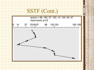
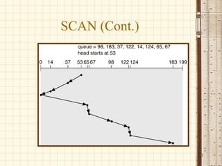
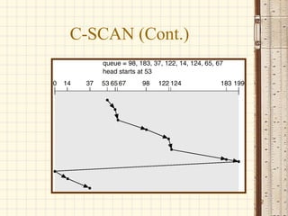
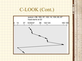
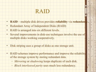
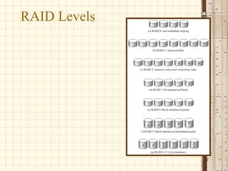
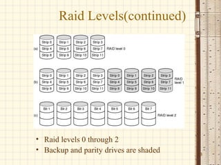
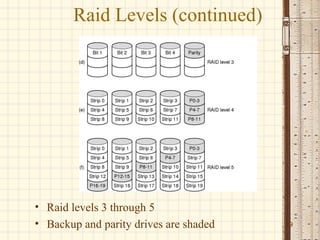
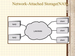
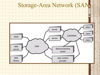
Disk Scheduling

Based on the slides supporting the
               text


                                     1
User-Space I/O Software


Layers of the I/O system and the main
functions of each layer                 2
Disk Structure
• Disk drives are addressed as large 1-dimensional arrays of
  logical blocks, where the logical block is the smallest unit of
  transfer.

• The 1-dimensional array of logical blocks is mapped into the
  sectors of the disk sequentially.
   – Sector 0 is the first sector of the first track on the outermost
      cylinder.
   – Mapping proceeds in order through that track, then the rest
      of the tracks in that cylinder, and then through the rest of the
      cylinders from outermost to innermost.
• Lets understand track, sector and cylinder concept.


                                                                         3
Disk Scheduling
• The operating system is responsible for using hardware
  efficiently — for the disk drives, this means having a fast access
  time and disk bandwidth.
• Access time has two major components
   – Seek time is the time for the disk are to move the heads to the
      cylinder containing the desired sector.
   – Rotational latency is the additional time waiting for the disk
      to rotate the desired sector to the disk head.
• Minimize seek time
• Seek time ≈ seek distance
• Disk bandwidth is the total number of bytes transferred, divided
  by the total time between the first request for service and the      4
  completion of the last transfer.
Disk Scheduling (Cont.)
• Several algorithms exist to schedule the servicing of
  disk I/O requests.
• We illustrate them with a request queue (0-199).

            98, 183, 37, 122, 14, 124, 65, 67

  Head pointer 53


                                                          5
FCFS


Illustration shows total head movement of 640 cylinders.
                                                           6
SSTF
• Selects the request with the minimum seek
  time from the current head position.
• SSTF scheduling is a form of SJF
  scheduling; may cause starvation of some
  requests.
• Illustration shows total head movement of
  236 cylinders.

                                              7
SSTF (Cont.)


               8
SCAN
• The disk arm starts at one end of the disk, and
  moves toward the other end, servicing requests
  until it gets to the other end of the disk, where
  the head movement is reversed and servicing
  continues.
• Sometimes called the elevator algorithm.
• Illustration shows total head movement of 208
  cylinders.
                                                      9
SCAN (Cont.)


               10
C-SCAN
• Provides a more uniform wait time than SCAN.
• The head moves from one end of the disk to the other.
  servicing requests as it goes. When it reaches the
  other end, however, it immediately returns to the
  beginning of the disk, without servicing any requests
  on the return trip.
• Treats the cylinders as a circular list that wraps around
  from the last cylinder to the first one.


                                                              11
C-SCAN (Cont.)


                 12
C-LOOK
• Version of C-SCAN
• Arm only goes as far as the last request in
  each direction, then reverses direction
  immediately, without first going all the way
  to the end of the disk.


                                                 13
C-LOOK (Cont.)


                 14
Selecting a Disk-Scheduling
              Algorithm
• SSTF is common and has a natural appeal
• SCAN and C-SCAN perform better for systems that place a
  heavy load on the disk.
• Performance depends on the number and types of requests.
• Requests for disk service can be influenced by the file-allocation
  method.
• The disk-scheduling algorithm should be written as a separate
  module of the operating system, allowing it to be replaced with
  a different algorithm if necessary.
• Either SSTF or LOOK is a reasonable choice for the default
  algorithm.
                                                                       15
RAID
•   RAID – multiple disk drives provides reliability via redundancy.
•   Redundant Array of Independent Disks (RAID)
•   RAID is arranged into six different levels.
•   Several improvements in disk-use techniques involve the use of
    multiple disks working cooperatively.

• Disk striping uses a group of disks as one storage unit.

• RAID schemes improve performance and improve the reliability
  of the storage system by storing redundant data.
   – Mirroring or shadowing keeps duplicate of each disk.
   – Block interleaved parity uses much less redundancy.
                                                                 16
RAID Levels


              17
Raid Levels(continued)


• Raid levels 0 through 2
• Backup and parity drives are shaded   18
Raid Levels (continued)


• Raid levels 3 through 5
• Backup and parity drives are shaded   19
Raid Levels 6 and 7
• RAID 6:P and Q redundancy
• RAID 7: heterogeneous disks array


                                      20
Disk Attachment
• Disks may be attached one of two ways:

1. Host attached via an I/O port

2. Network attached via a network
   connection


                                           21
Network-Attached Storage(NAS)


                            22
Storage-Area Network (SAN)


                         23
Summary
• We looked various disk scheduling methods
  to optimize secondary storage access.
• We also studies basic principles of RAID.
• NAS and SAN are two recent advances in
  secondary storage.


                                              24

Disk scheduling geekssay.com

  • 1.
    Disk Scheduling Based onthe slides supporting the text 1
  • 2.
    User-Space I/O Software Layersof the I/O system and the main functions of each layer 2
  • 3.
    Disk Structure • Diskdrives are addressed as large 1-dimensional arrays of logical blocks, where the logical block is the smallest unit of transfer. • The 1-dimensional array of logical blocks is mapped into the sectors of the disk sequentially. – Sector 0 is the first sector of the first track on the outermost cylinder. – Mapping proceeds in order through that track, then the rest of the tracks in that cylinder, and then through the rest of the cylinders from outermost to innermost. • Lets understand track, sector and cylinder concept. 3
  • 4.
    Disk Scheduling • Theoperating system is responsible for using hardware efficiently — for the disk drives, this means having a fast access time and disk bandwidth. • Access time has two major components – Seek time is the time for the disk are to move the heads to the cylinder containing the desired sector. – Rotational latency is the additional time waiting for the disk to rotate the desired sector to the disk head. • Minimize seek time • Seek time ≈ seek distance • Disk bandwidth is the total number of bytes transferred, divided by the total time between the first request for service and the 4 completion of the last transfer.
  • 5.
    Disk Scheduling (Cont.) •Several algorithms exist to schedule the servicing of disk I/O requests. • We illustrate them with a request queue (0-199). 98, 183, 37, 122, 14, 124, 65, 67 Head pointer 53 5
  • 6.
    FCFS Illustration shows totalhead movement of 640 cylinders. 6
  • 7.
    SSTF • Selects therequest with the minimum seek time from the current head position. • SSTF scheduling is a form of SJF scheduling; may cause starvation of some requests. • Illustration shows total head movement of 236 cylinders. 7
  • 8.
  • 9.
    SCAN • The diskarm starts at one end of the disk, and moves toward the other end, servicing requests until it gets to the other end of the disk, where the head movement is reversed and servicing continues. • Sometimes called the elevator algorithm. • Illustration shows total head movement of 208 cylinders. 9
  • 10.
  • 11.
    C-SCAN • Provides amore uniform wait time than SCAN. • The head moves from one end of the disk to the other. servicing requests as it goes. When it reaches the other end, however, it immediately returns to the beginning of the disk, without servicing any requests on the return trip. • Treats the cylinders as a circular list that wraps around from the last cylinder to the first one. 11
  • 12.
  • 13.
    C-LOOK • Version ofC-SCAN • Arm only goes as far as the last request in each direction, then reverses direction immediately, without first going all the way to the end of the disk. 13
  • 14.
  • 15.
    Selecting a Disk-Scheduling Algorithm • SSTF is common and has a natural appeal • SCAN and C-SCAN perform better for systems that place a heavy load on the disk. • Performance depends on the number and types of requests. • Requests for disk service can be influenced by the file-allocation method. • The disk-scheduling algorithm should be written as a separate module of the operating system, allowing it to be replaced with a different algorithm if necessary. • Either SSTF or LOOK is a reasonable choice for the default algorithm. 15
  • 16.
    RAID • RAID – multiple disk drives provides reliability via redundancy. • Redundant Array of Independent Disks (RAID) • RAID is arranged into six different levels. • Several improvements in disk-use techniques involve the use of multiple disks working cooperatively. • Disk striping uses a group of disks as one storage unit. • RAID schemes improve performance and improve the reliability of the storage system by storing redundant data. – Mirroring or shadowing keeps duplicate of each disk. – Block interleaved parity uses much less redundancy. 16
  • 17.
  • 18.
    Raid Levels(continued) • Raidlevels 0 through 2 • Backup and parity drives are shaded 18
  • 19.
    Raid Levels (continued) •Raid levels 3 through 5 • Backup and parity drives are shaded 19
  • 20.
    Raid Levels 6and 7 • RAID 6:P and Q redundancy • RAID 7: heterogeneous disks array 20
  • 21.
    Disk Attachment • Disksmay be attached one of two ways: 1. Host attached via an I/O port 2. Network attached via a network connection 21
  • 22.
  • 23.
  • 24.
    Summary • We lookedvarious disk scheduling methods to optimize secondary storage access. • We also studies basic principles of RAID. • NAS and SAN are two recent advances in secondary storage. 24