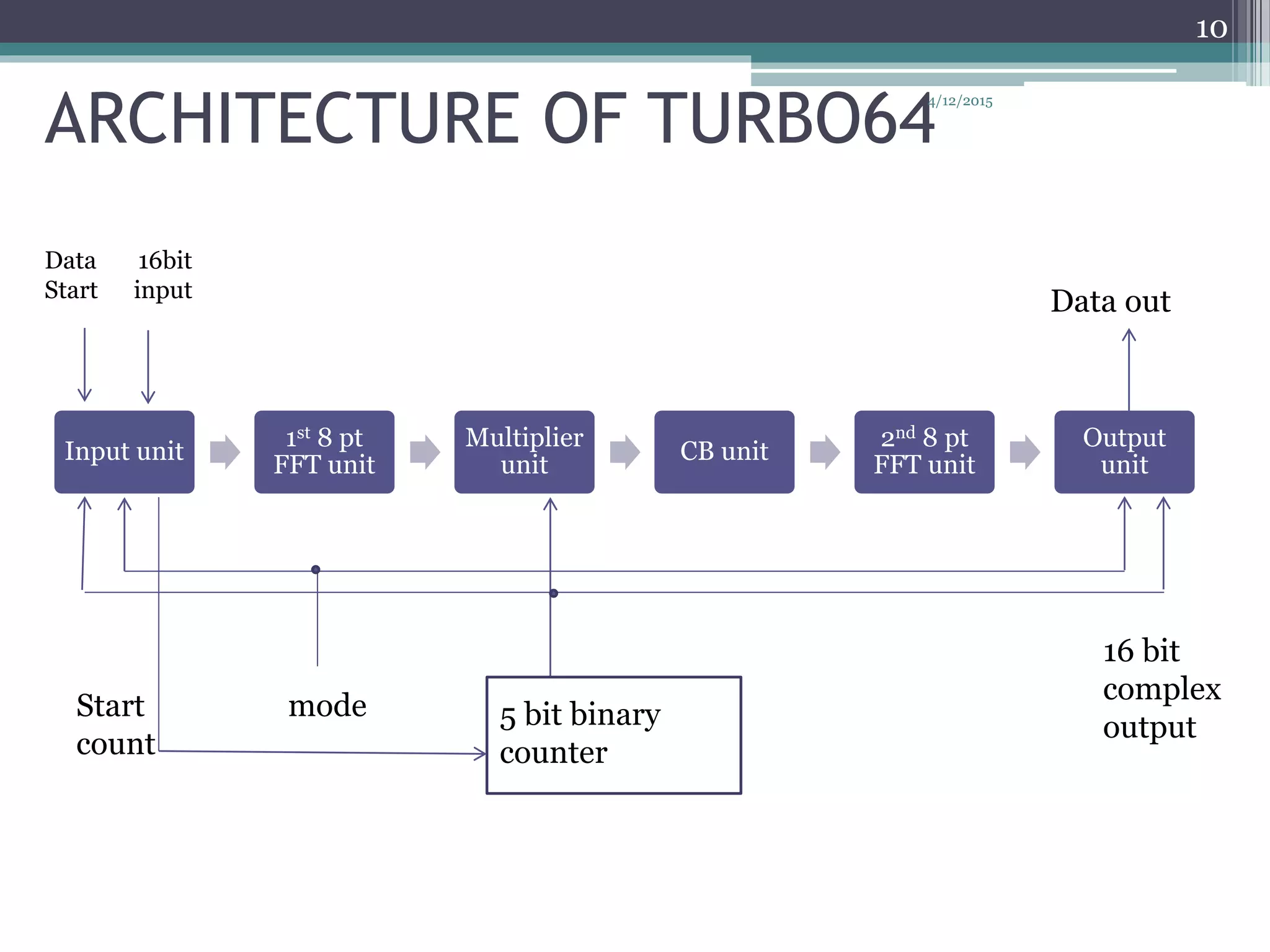
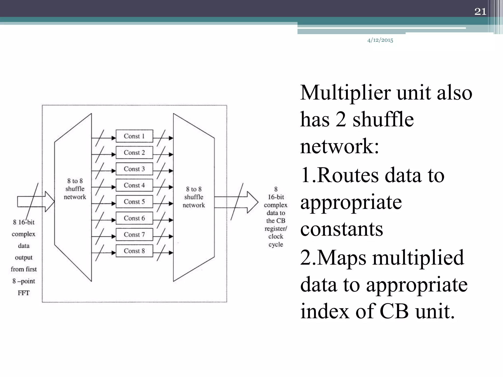
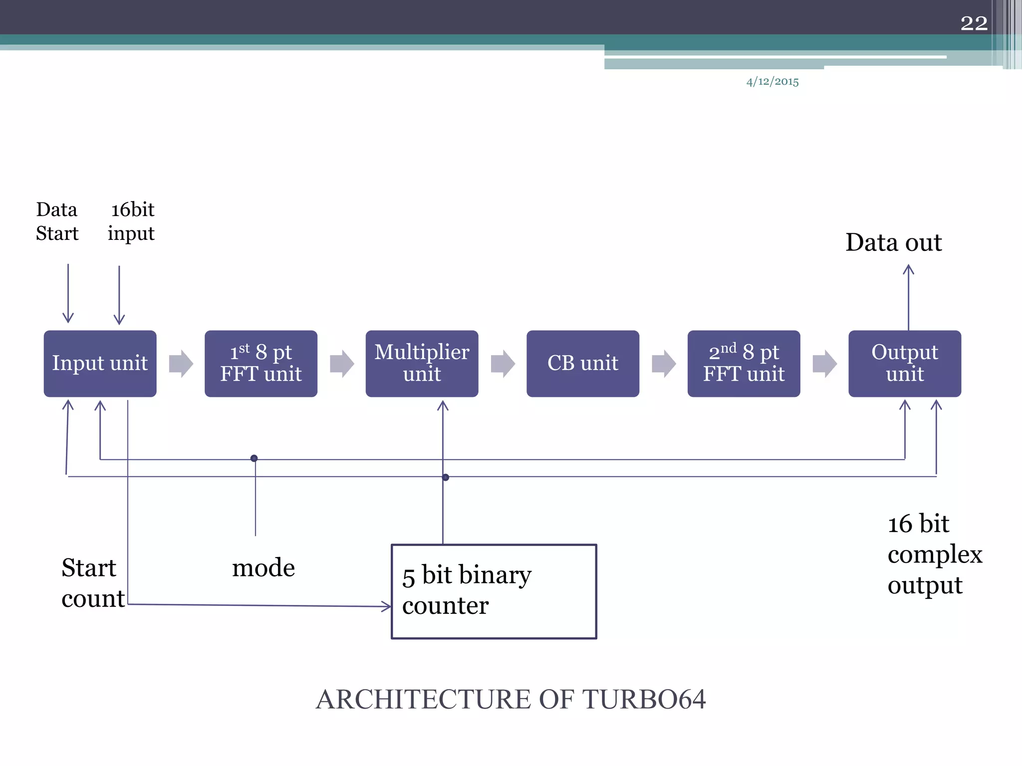
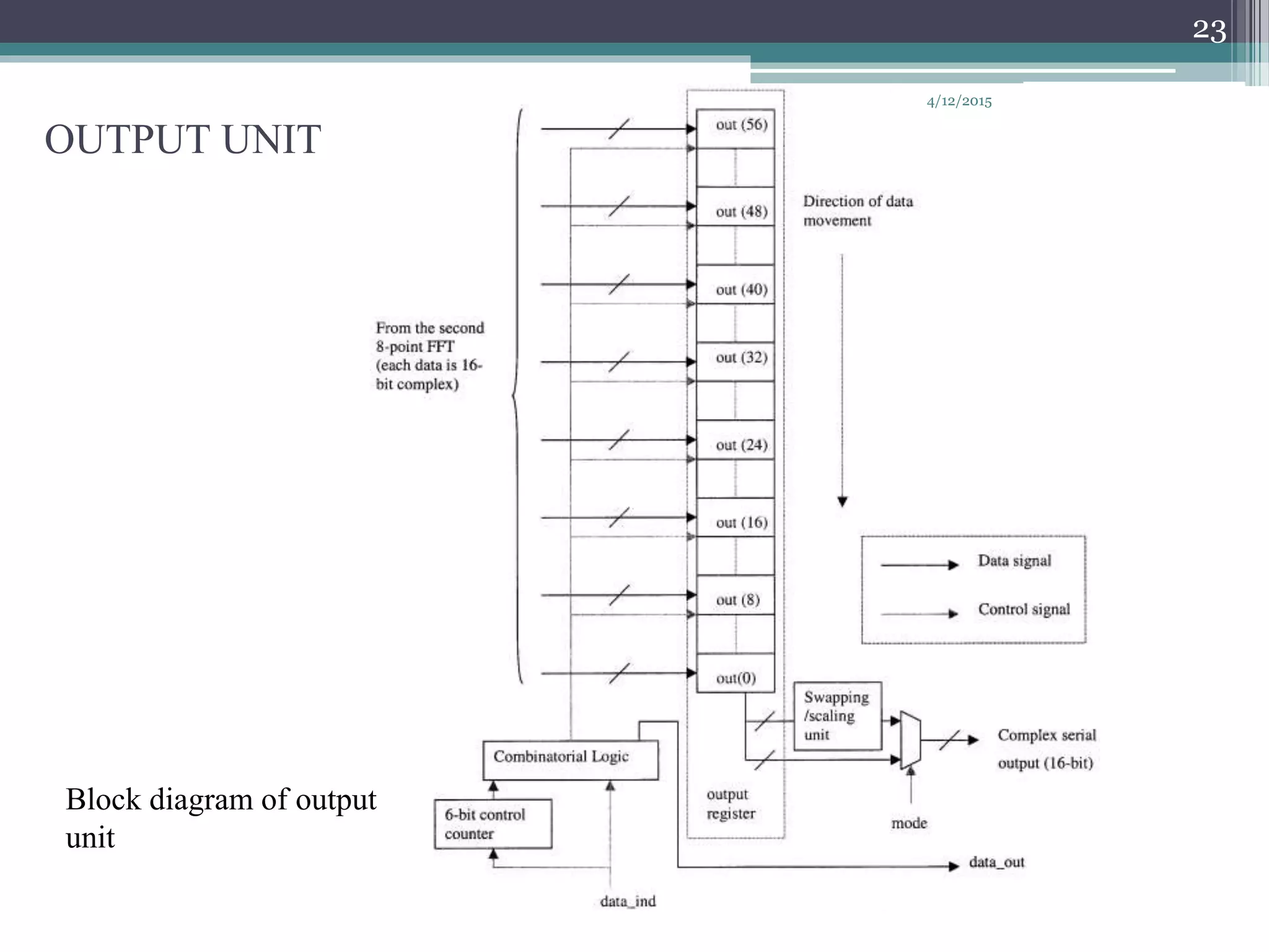
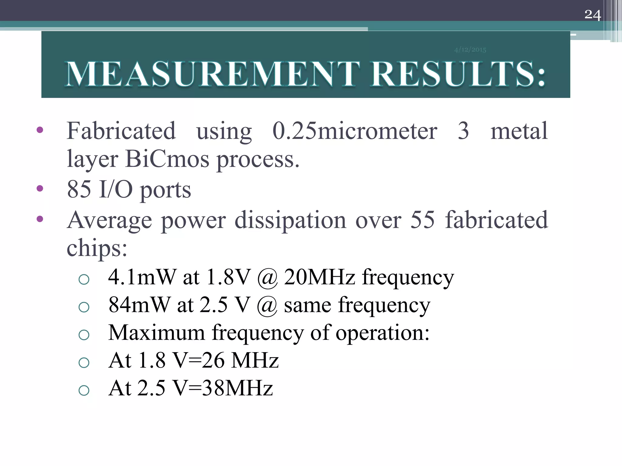
This document presents the design of a 64 point fast Fourier transform (FFT) processor called Turbo64. It uses a radix-2 decimation-in-time algorithm to decompose a 64 point FFT into two 8 point FFTs. The architecture includes input, multiplier, constant buffer, and output units. The multiplier unit utilizes constant multiplication through hard-wired representations of constants. Fabricated in 0.25um BiCMOS, Turbo64 has a core area of 6.8 sq mm and power consumption of 41 mW, making it suitable for applications like OFDM used in wireless communications standards.
![A(s+Tt)= 𝑙=0
𝑇−1
𝑊 𝑙𝑡
𝑀[𝑊 𝑠𝑙
𝑀𝑇 𝑚=0
𝑇−1
𝐵(𝑙 + 𝑀𝑚)𝑊 𝑠𝑚
𝑇
]………….2
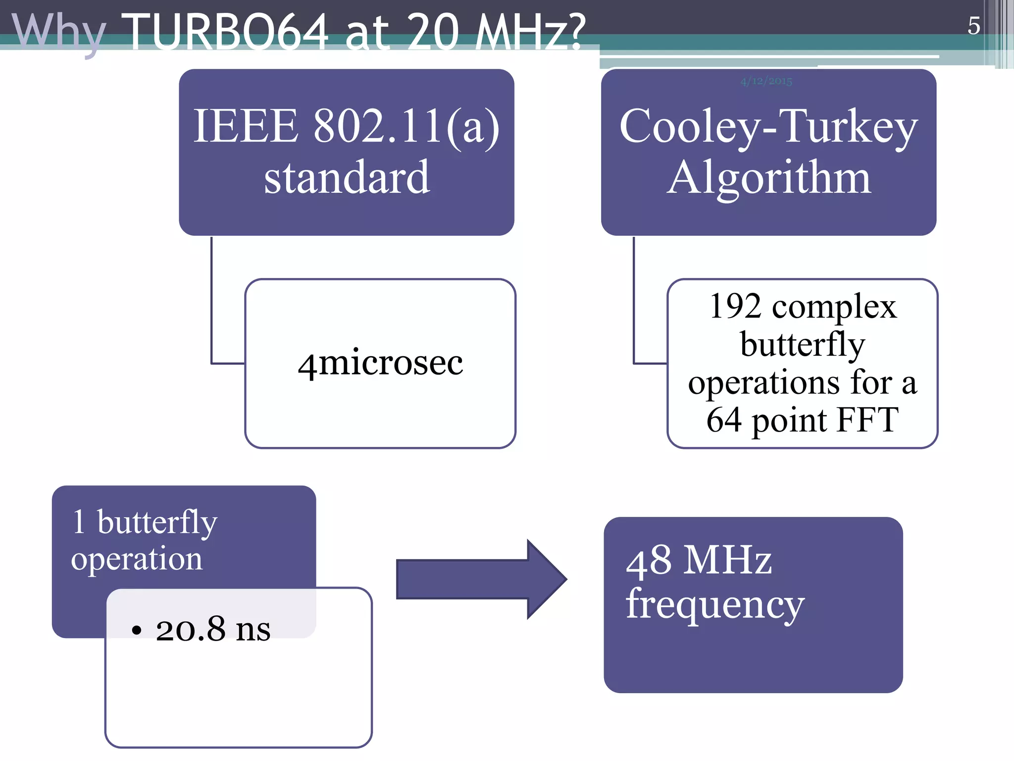
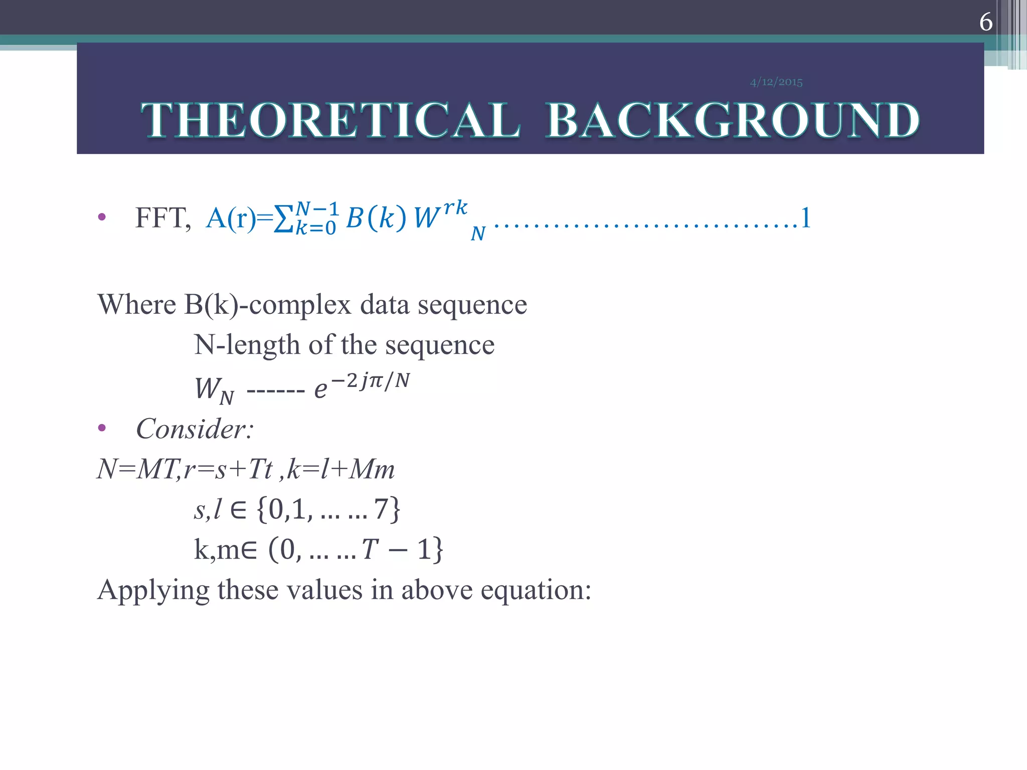
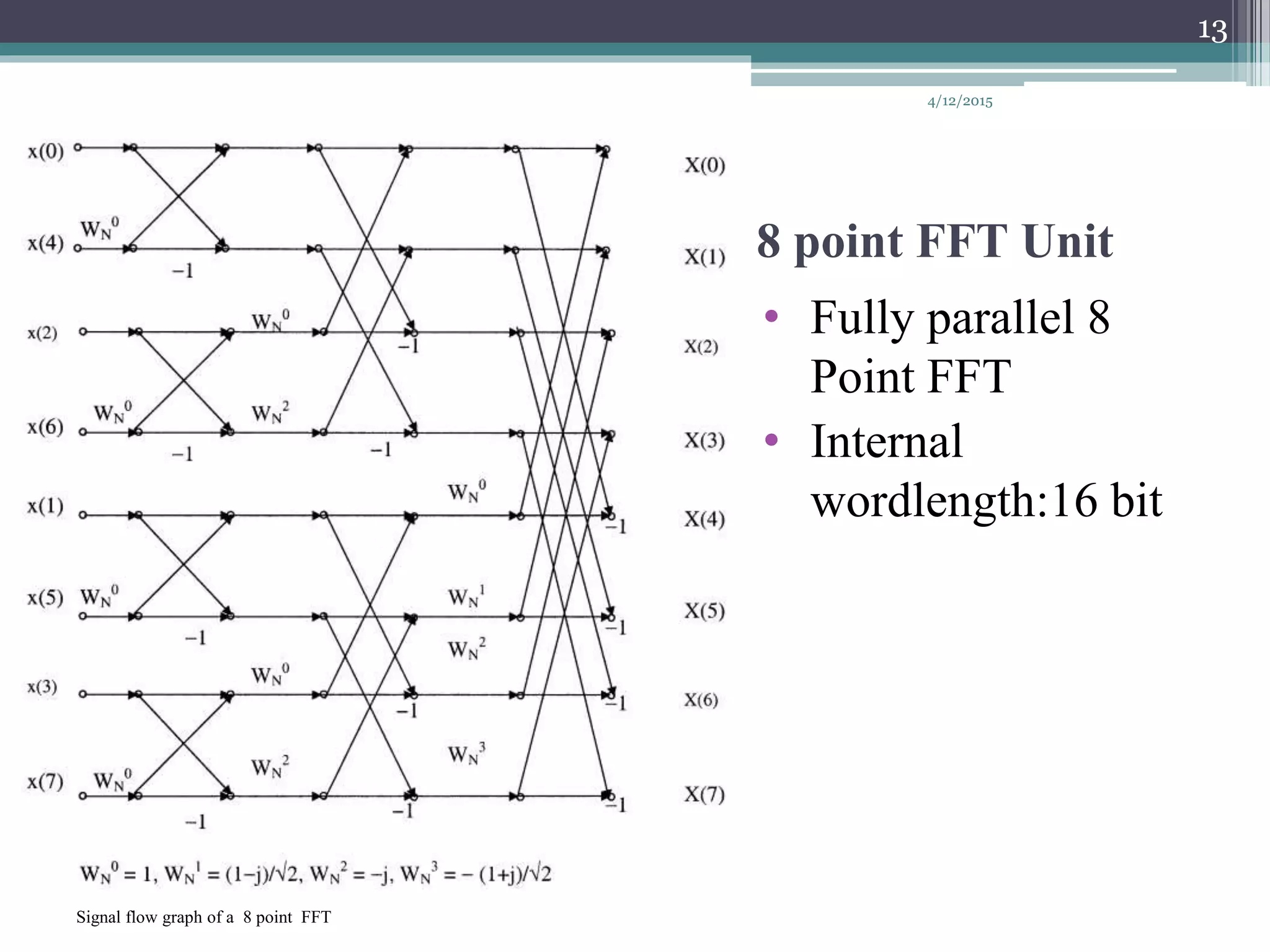
• Eqn (2) FFT decomposed into M point and T point FFT
And combined for final result.
• Considering M=8 and T=8: the 64 point FFT can be expressed as:
A(s+Tt)= 𝑙=0
7
𝑊 𝑙𝑡
8 [𝑊 𝑠𝑙
64 𝑚=0
7
𝐵(𝑙 + 8𝑚)𝑊 𝑠𝑚
8
]………
3
4/12/2015
7](https://image.slidesharecdn.com/64pointfftchip-150412110732-conversion-gate01/75/64-point-fft-chip-7-2048.jpg)
![REFERENCES
• [1]A 64 point fourier transform chp for high speed
wireless LAN application using OFDM-
K.Maharatna,E.Grass,U.Jaghold
• [2] A. M. Despain, “Very fast Fourier transform
algorithms hardware for implementation,” IEEE
Trans. Comput., vol. C-28, no. 5, pp. 333–341,1979.
• [3]C. Chen and L.Wang, “A new efficient systolic
architecture for the 2-D discrete Fourier transform,”
in Proc. IEEE Int. Symp. Circuits and Systems,vol.
6, ch. 732, 1992, pp. 689–692.
4/12/2015
27](https://image.slidesharecdn.com/64pointfftchip-150412110732-conversion-gate01/75/64-point-fft-chip-27-2048.jpg)