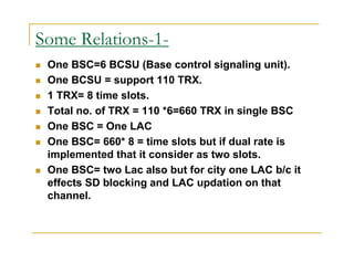
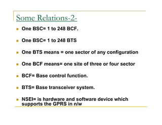
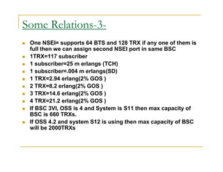
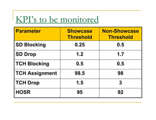
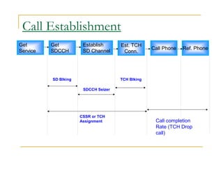
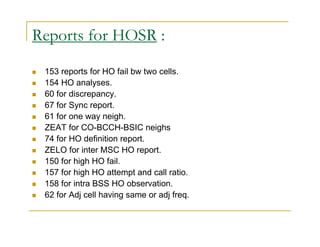
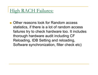
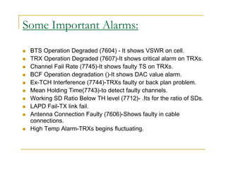
Call Setup Success Rate Definition and Troubleshooting Assim Mubder
The CSSR indicates the probability of successful calls initiated by the MS. The CSSR is an important KPI for evaluating the network performance. If this KPI is too low, the subscribers are not likely to make calls successfully. The user experience is thus affected.
SDCCH definition, understanding, and troubleshooting.
What is the SDCCHs blocking rate?
The sdcch_blocking_rate statistic tracks the percentage of attempts to allocate an sdcch that were blocked due to no available sdcch resources
Coverage verification
New site Performance Verification and Field optimization
Network Problem trouble shooting like Drop calls, Handover failure, Poor Coverage patches, Poor RX Quality patches, etc
Benchmarking Drive test to find out Coverage and Quality comparison against competitors networks
• -How the channel concept is used on the radio interface
• -Different burst formats in the radio interface
• -The hierarchical frame structure
• -The content sent in different logical channels
• -The mapping of the logical channels
• -Superframe and Hyperframe
• -MOBILE STATIONS ISDN NUMBER (MSISDN)
• INTERNATIONAL MOBILE SUBSCRIBER IDENTITY (IMSI)
• TEMPORARY MOBILE SUBSCRIBER IDENTITY (TMSI)
• LOCATION AREA IDENTITY (LAI)
• CELL GLOBAL IDENTITY (CGI)
• BASE STATION IDENTITY CODE (BSIC)
• PIN management
Engineer EMERSON EDUARDO RODRIGUES PRESENTA UNA NUEVA VERSION
THERE ONE NEW ONE PRESENTATION FOR 2G AND 3G ENGINEERING FOR LTE AND PSCORE ENGINEER
ITS VERY SUITABLE FOR YOUR RESEARCH AT ALL LEVELS OF RF ENGINEERING AND PS CS
Overview of the fundamental roles in Hydropower generation and the components involved in wider Electrical Engineering.
This paper presents the design and construction of hydroelectric dams from the hydrologist’s survey of the valley before construction, all aspects and involved disciplines, fluid dynamics, structural engineering, generation and mains frequency regulation to the very transmission of power through the network in the United Kingdom.
Author: Robbie Edward Sayers
Collaborators and co editors: Charlie Sims and Connor Healey.
(C) 2024 Robbie E. Sayers
CFD Simulation of By-pass Flow in a HRSG module by R&R Consult.pptxR&R Consult
CFD analysis is incredibly effective at solving mysteries and improving the performance of complex systems!
Here's a great example: At a large natural gas-fired power plant, where they use waste heat to generate steam and energy, they were puzzled that their boiler wasn't producing as much steam as expected.
R&R and Tetra Engineering Group Inc. were asked to solve the issue with reduced steam production.
An inspection had shown that a significant amount of hot flue gas was bypassing the boiler tubes, where the heat was supposed to be transferred.
R&R Consult conducted a CFD analysis, which revealed that 6.3% of the flue gas was bypassing the boiler tubes without transferring heat. The analysis also showed that the flue gas was instead being directed along the sides of the boiler and between the modules that were supposed to capture the heat. This was the cause of the reduced performance.
Based on our results, Tetra Engineering installed covering plates to reduce the bypass flow. This improved the boiler's performance and increased electricity production.
It is always satisfying when we can help solve complex challenges like this. Do your systems also need a check-up or optimization? Give us a call!
Work done in cooperation with James Malloy and David Moelling from Tetra Engineering.
More examples of our work https://www.r-r-consult.dk/en/cases-en/
Sachpazis:Terzaghi Bearing Capacity Estimation in simple terms with Calculati...Dr.Costas Sachpazis
Terzaghi's soil bearing capacity theory, developed by Karl Terzaghi, is a fundamental principle in geotechnical engineering used to determine the bearing capacity of shallow foundations. This theory provides a method to calculate the ultimate bearing capacity of soil, which is the maximum load per unit area that the soil can support without undergoing shear failure. The Calculation HTML Code included.
Welcome to WIPAC Monthly the magazine brought to you by the LinkedIn Group Water Industry Process Automation & Control.
In this month's edition, along with this month's industry news to celebrate the 13 years since the group was created we have articles including
A case study of the used of Advanced Process Control at the Wastewater Treatment works at Lleida in Spain
A look back on an article on smart wastewater networks in order to see how the industry has measured up in the interim around the adoption of Digital Transformation in the Water Industry.
About
Indigenized remote control interface card suitable for MAFI system CCR equipment. Compatible for IDM8000 CCR. Backplane mounted serial and TCP/Ethernet communication module for CCR remote access. IDM 8000 CCR remote control on serial and TCP protocol.
• Remote control: Parallel or serial interface.
• Compatible with MAFI CCR system.
• Compatible with IDM8000 CCR.
• Compatible with Backplane mount serial communication.
• Compatible with commercial and Defence aviation CCR system.
• Remote control system for accessing CCR and allied system over serial or TCP.
• Indigenized local Support/presence in India.
• Easy in configuration using DIP switches.
Technical Specifications
Indigenized remote control interface card suitable for MAFI system CCR equipment. Compatible for IDM8000 CCR. Backplane mounted serial and TCP/Ethernet communication module for CCR remote access. IDM 8000 CCR remote control on serial and TCP protocol.
Key Features
Indigenized remote control interface card suitable for MAFI system CCR equipment. Compatible for IDM8000 CCR. Backplane mounted serial and TCP/Ethernet communication module for CCR remote access. IDM 8000 CCR remote control on serial and TCP protocol.
• Remote control: Parallel or serial interface
• Compatible with MAFI CCR system
• Copatiable with IDM8000 CCR
• Compatible with Backplane mount serial communication.
• Compatible with commercial and Defence aviation CCR system.
• Remote control system for accessing CCR and allied system over serial or TCP.
• Indigenized local Support/presence in India.
Application
• Remote control: Parallel or serial interface.
• Compatible with MAFI CCR system.
• Compatible with IDM8000 CCR.
• Compatible with Backplane mount serial communication.
• Compatible with commercial and Defence aviation CCR system.
• Remote control system for accessing CCR and allied system over serial or TCP.
• Indigenized local Support/presence in India.
• Easy in configuration using DIP switches.
Saudi Arabia stands as a titan in the global energy landscape, renowned for its abundant oil and gas resources. It's the largest exporter of petroleum and holds some of the world's most significant reserves. Let's delve into the top 10 oil and gas projects shaping Saudi Arabia's energy future in 2024.
Student information management system project report ii.pdfKamal Acharya
Our project explains about the student management. This project mainly explains the various actions related to student details. This project shows some ease in adding, editing and deleting the student details. It also provides a less time consuming process for viewing, adding, editing and deleting the marks of the students.
Hierarchical Digital Twin of a Naval Power SystemKerry Sado
A hierarchical digital twin of a Naval DC power system has been developed and experimentally verified. Similar to other state-of-the-art digital twins, this technology creates a digital replica of the physical system executed in real-time or faster, which can modify hardware controls. However, its advantage stems from distributing computational efforts by utilizing a hierarchical structure composed of lower-level digital twin blocks and a higher-level system digital twin. Each digital twin block is associated with a physical subsystem of the hardware and communicates with a singular system digital twin, which creates a system-level response. By extracting information from each level of the hierarchy, power system controls of the hardware were reconfigured autonomously. This hierarchical digital twin development offers several advantages over other digital twins, particularly in the field of naval power systems. The hierarchical structure allows for greater computational efficiency and scalability while the ability to autonomously reconfigure hardware controls offers increased flexibility and responsiveness. The hierarchical decomposition and models utilized were well aligned with the physical twin, as indicated by the maximum deviations between the developed digital twin hierarchy and the hardware.
2. Some Relations-1-
One BSC=6 BCSU (Base control signaling unit).
One BCSU = support 110 TRX.
1 TRX= 8 time slots.
Total no. of TRX = 110 *6=660 TRX in single BSC
One BSC = One LAC
One BSC= 660* 8 = time slots but if dual rate is
implemented that it consider as two slots.
One BSC= two Lac also but for city one LAC b/c it
effects SD blocking and LAC updation on that
channel.
3. Some Relations-2-
One BSC= 1 to 248 BCF.
One BSC= 1 to 248 BTS
One BTS means = one sector of any configuration
One BCF means= one site of three or four sector
BCF= Base control function.
BTS= Base transceiver system.
NSEI= is hardware and software device which
supports the GPRS in n/w
4. Some Relations-3-
One NSEI= supports 64 BTS and 128 TRX if any one of them is
full then we can assign second NSEI port in same BSC
1TRX=117 subscriber
1 subscriber=25 m erlangs (TCH)
1 subscriber=.004 m erlangs(SD)
1 TRX=2.94 erlang(2% GOS )
2 TRX=8.2 erlang(2% GOS )
3 TRX=14.6 erlang(2% GOS )
4 TRX=21.2 erlang(2% GOS )
If BSC 3VI, OSS is 4 and System is S11 then max capacity of
BSC is 660 TRXs.
If OSS 4.2 and system S12 is using then max capacity of BSC
will be 2000TRXs
5. KPI’s to be monitored
SD Blocking
SD Drop
TCH Blocking
TCH Assignment
TCH Drop
HOSR
6. Non-Showcase
Threshold
KPI’s to be monitored
Showcase
Threshold
Parameter
SD Blocking 0.25 0.5
SD Drop 1.2 1.7
TCH Blocking 0.5 0.5
TCH Assignment 98.5 98
TCH Drop 1.5 3
HOSR 95 92
7. Call Establishment
Get
Service
Get
SDCCH
Establish
SD Channel
Est. TCH
Conn.
Call Phone Ref. Phone
SD Blking
SDCCH Seizer
TCH Blking
CSSR or TCH
Assignment
Call completion
Rate (TCH Drop
call)
8. What is Dropped Call?
All cell resources are available but calls are failing,
then we have a call drop scenario. This could be
caused by software errors, congestion, C7 link
failures,HW problems or many other reasons.
If a call is abnormally disconnected, a Clear Request
is sent to the MSC .If the Call is disconnected in a
normal Fashion then Clear Message with cause code
Call Control is sent. It is important to establish what
types of calls are failing, and over what percentage of
the network it is occurring.
9. SDCCH CHANNEL :
SDCCH is a dedicated channel which is
using for LAC updation, Call setup, SMS in
idle mode. It works in UL DL.
10. SD Blocking:
SD blocking means that you are not getting
SD resource for the call origination. When
MS connects with NW then RACH and AGCH
are provided. After AGCH,SDCCH is
provided but if SDCCH is not provided at this
time due some problems or due to
unavailable of SD by BSC ,it’s called as SD
Blocking. There are no of reasons for that.If
such a case arises the customer will not be
able to originate any call.
11. Difference Between Blocking and
Congestion:
It is very important to know difference
between blocking and congestion. Some
people think that both are same, but they
differ from each other. If all the SD resources
are full and not available for SD assign then
its come into congestion. If at a particular
time call is attempted and it fails then it
known as Blocking.
12. Reasons for SD Blocking:
Some of them are-
LAC boundary.
HW Prob.
13. Solutions for removal of SD Blocking:
Here are some steps by which we can reduce SD
Blocking-
1. Check the No. of SDCCH channel Available, if less then
increase SD channel taking care that there is no TCH Blocking.
2. Check LAC boundary, If location update is more then change the
LAC of that site and set C2 and HYS.
3. Use of Dynamic SDCCH (It is a BSC parameter and will be
applied on whole BTS).
4. Hardware check / shift SD to new time slot
5. Some times BMA and HYS parameters are useful to remove SD
Blocking.
14. Usefull Reports For SD Blocking:
Use 182 to analyses SD Blocking reasons.
130 for SD congestion.
15. SD Drop:
As per diagram shows when we assigned SD for call
origination and at that time due to some problem or any
mismatch comes by which SD loss occurs, it is called as
SD Drop.
It occurs between allocation of SD and before TCH
allocation. Sometimes SD drop occurs because queuing
is not activated in the system.
If SD drop is high plz look on parameters like-overshooting
, shift the SD time slot , may be hardware
issue, interference, change the values of RXP, PMAX,
may be issue of uplink or downlink issue in that cells for
UL put a TMA in that cell and for DL provide tilt ,re orient
that antenna
16. If SD Drop is high:
If SD drop is high plz look on parameters like-
Overshooting
Shift the SD time slot
Hardware issue
Interference
Change the values of RXP PMAX
It may be uplink or downlink issue in which cells for UL
put a TMA in that cell and for DL provide tilt
Re orient that antenna
17. Reasons of SD Drop:
Hardware Fault.
Interference.
MAIO mismatch.
Bad Coverage.
High TR Fail.
Outage.
Overshooting.
Abis Drop.
High Path Loss.
Wrong Parameter Planning.
Due to ICM Band(CDMA)
High LAPD Utilization
Heavy blocking and DR feature being used extensively
18. Solutions for removal of SD Drop:
Interference:
Check the BCCH Plan (C/I or C/A).
Co-BSIC Co BCCH.
Use latest ND 111 and MapInfo to find out proper
frequency to reduce interference.
Arrange Drive Test:
The best way to find the real issues for Interference
makes DT.
Check interference by Interference scanning.
Check clean BCCH by frequency scanning.
19. Overshooting:
LAC Planning.
If a cell is picking call from long distance,
Check the sample log according to TA.
Cell orientation need to be defined according
to clutter.
Mount position
Effective Tilt.
20. Cont…
High TR Fail:
Check and clear TR fail from OSS end.
Bad Coverage:
If the drop call is due to low signal strength uplink, check the
receive path of this particular TRX. Check receiver sensitivity,
VSWR, feeder connection and etc. Drops due to Low Signal
Strength.
If the drop call reason is due to low signal strength downlink,
then, check the transmit path. Check cards, feeder and etc.
Use MapInfo or Google Earth to find location of sites.
21. Cont..
High LAPD Utilization:
Check LAPD util report from OSS, and define 32 kbps signaling
instead of 16kbps
Hardware Fault:
Check Alarms.
TRX condition.
Check Path Imbalance.
VSWR of the Cell.
Connector Connection.
Some times you will find issues on BCCH TRX.In this case
BCCH shift from one to other TRX will reduce SD drop.
22. Cont…
Due to ICM Band(CDMA):
Some time SD drops takes place due to near sites of
CDMA.
Check the ICM band value of that site.
Use BPF (Band pass filter).
Use the spectrum analyzer.
23. Cont..
Check for parameter:
Check the Timer T 3101
Check the Timer T 200(20ms)
T11 Expired(10 s)
MAIO check.
24. Useful Reports for SD Drop:
Use report ZEOL to find the alarms.
Use 208 for Path loss analysis.
Use 196 for UL-DL Interference.
Use 163 report for SD drop.
Use report 216 for detail SD Drop.
232 report for TA report.
62 for Adj cell having same or adj freq.
ND 111 for freq plan.
204 for BTS and cell report.
25. TCH Blocking:
When TCH is not allocated to the user
after SD allocation ,it is TCH Blocking.
It is the failed call attempts which the MS
user can notice.
It takes place due to lack of TCH
Resource.
26. Reasons for TCH Blocking:
Some of them are-
High Utilization of TCH
Time slot faulty.
Lock TRXs.
HW Problem.
27. Solutions for removal of TCH Blocking:
Implement half rate or Dual rate.
Check FRL FRU.
Add another TRX.
If TRX addition not possible, try to share the
traffic of that cell with the neighboring cell by
changing tilt or orientation.
29. TCH Assignment:
It’s a process of by which TCH is assigned to
the MS.
After the SD request MS gets TCH
successfully and the call transfers to TCH it
means TCH assignment is successful.
For the best KPI TCH assignment should
tend to 100%.
It degrades due to HW problems.
30. Reasons for TCH Assignment failure:
Hardware
Fault(TRXs,Combiner,Duplexer,Cables)
VSWR
High Path Loss.
Faulty TMA.
High TCH Blocking.
Loose connections.
DR being used extensively
31. Solutions for removal of TCH Assignment:
Clear VSWR
IF TRXs are faulty lock them and try to replace
them soon to avoid blocking
Path Imbalance clear.
Connection from BTS to Antenna
Connector connection
Check TMA.
Check Duplexer,Combiner,TRXs
connections,Multicuppler etc.
Check BOIA card.
Check BB2F Card.
32. Reports for TCH Assignment:
ZEOL to check alarms
208 for path imbalance
196 for UL-DL interference
ZAHP for Flick report
33. TCH Drop:
Drop during conversation is known as TCH
drop. It takes place after connect ACK msg
on TCH.TCH drop occurring.
For TCH drop first cross check the BCCH of
that cell, hardware issue may be, change
RXP and RLT value. Find out there is any
interference ,neighbor defined.
34. Reasons for TCH Drop:
Wrong Parameter Planning.
BAD HOSR.
Hardware Fault.
High TR Fail.
Overshoot.
Outage.
Due to Low Coverage.
Due to ICM Band(CDMA)
35. Solutions for removal of TCH Drop:
Check Parameter:
Check the BCCH Plan (C/I or C/A).
Co-BSIC Co BCCH.
Check the Timer T 100(should be 20 ms)
Check Overshooting:
If a cell is picking call from long distance,
Check the sample log according to TA..
Site Orientation.
Effective tilt should be check.
Mount position should be check
36. Cont..
Improve HOSR:
Check the Hopping plan.
Check the Neighbor Plan
High TR Fail:
Check and clear TR fail from oss end.
37. Cont..
Bad Coverage:
If the drop call is due to low signal strength uplink, check the
receive path of this particular TRX. Check receiver sensitivity,
VSWR, feeder connection and etc. Drops due to Low Signal
Strength.
If the drop call reason is due to low signal strength downlink, then,
check the transmit path. Check cards, feeder and etc.
Use MapInfo or Google Earth to find location of sites.
Effective tilt should be check.
Mount position should be check.
39. Cont..
Drop Reason because of HW Issues:
if drops are only on one site, then go for a check for that particular
even attach with that site.
If drops are on all sites connected to a single link, then check the
slip or interference on that Abis interface.
If Drops are distributed on all site of the BSC, then check the slips
on A-ter.
Down Time of the cell.
TRX condition.
BTS should not getting the temperature alarm continuously.
40. Reports for TCH Drop:
166 for TCH Drop
ZEOL for alarms.
ZAHP for Flicks.
232 for TA report.
208 Path Imbalance report.
204 for BTS report.
216 for all parameter.
196 for UL-DL Qul.
62 for Adj cell having same or adj freq.
41. HOSR:
Hand over success rate:
If HOSR will be good TCH drop will also be
good.
If Handover success rate degrades call drop
rate will take place.
42. Reasons for HOSR:
Improper Neighbor planning.
CO-BCCH-BSIC issues in Neigh.
Parameter Check.
HSN clash.
SL value.
LAC boundary.
DAC value mismatch.
Syn mismatch.
Overshoot.
HW Issues.
Low Coverage
43. Solutions for removal of HOSR:
Arrange Drive Test:
The best way to find the real issues for HO fail make
DT and check layer 3 msg gor HO fail.By DT it is very
easy to find the fail between cells.
Neighbor Tuning:
Try to retune neighbors
Avoid CO-BCCH-BSIC neighbors.
Avoid extra neighs.
Delete long distance neighs.
Check neighs are defined form both ends.
If there are high fail delete and recreate neighs.
44. Cont..
Parameter Check:
1. Retune SL.It can change bw -90,-95,-105.
2. Check HSN.
3. Check SYN.
4. Retune LDR, LUR, IDR, IUR.
5. Retune LMRG, QMRG, PMRG.
DAC value Check:
1. Check DAC value. If DAC value is high or low tune it at
the TH value. It should be 2050.
45. Cont..
Overshoot:
When neighs are far away then chances of HO fail increases. In
this case ping-pong HI takes place by which fail takes place. So it
the inter distance is high its batter to del that kind of neigh.
LAC Boundary-
Check LAC boundry.
High fail takes place there will be Inter BSC cells.
High fail takes place there will be Inter MSC cells.
Define proper LAC in neigh cells.
46. Cont..
HW Issues:
Clear HW issues.
Check TRXs.
Check outages.
Check BOIA Card. Because if it is faulty incoming and outgoing
HO will be fail.
Clear Reports:
Clear ZEAT.
Clear 60.
Clear 67.
Clear 61.
47. Reports for HOSR :
153 reports for HO fail bw two cells.
154 HO analyses.
60 for discrepancy.
67 for Sync report.
61 for one way neigh.
ZEAT for CO-BCCH-BSIC neighs
74 for HO definition report.
ZELO for inter MSC HO report.
150 for high HO fail.
157 for high HO attempt and call ratio.
158 for intra BSS HO observation.
62 for Adj cell having same or adj freq.
48. High RACH Failures:
Other reasons look for Random access
statistics, if there is a lot of random access
failures try to check hardware too. It includes
thorough hardware audit including CF
Reloading, IDB Setting and reloading,
Software synchronization, filter check etc)
49. Some Important Alarms:
BTS Operation Degraded (7604) - It shows VSWR on cell.
TRX Operation Degraded (7607)-It shows critical alarm on TRXs.
Channel Fail Rate (7745)-It shows faulty TS on TRXs.
BCF Operation degradation ()-It shows DAC value alarm.
Ex-TCH Interference (7744)-TRXs faulty or back plan problem.
Mean Holding Time(7743)-to detect faulty channels.
Working SD Ratio Below TH level (7712)- .Its for the ratio of SDs.
LAPD Fail-TX link fail.
Antenna Connection Faulty (7606)-Shows faulty in cable
connections.
High Temp Alarm-TRXs begins fluctuating.