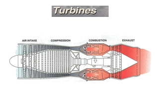
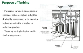
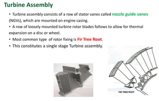
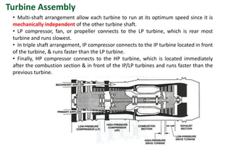
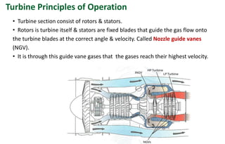
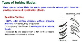
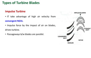
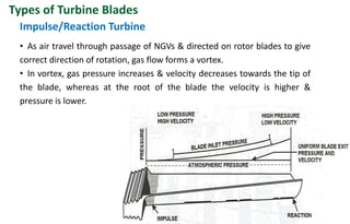
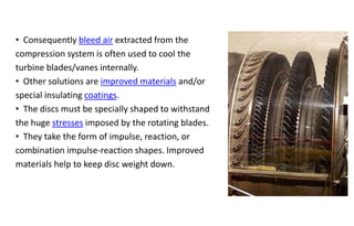
Purpose of Turbine
• Purpose of turbine is to use some of
energy of hot gases to turn a shaft for
driving the compressor, or in case of a
turboprop, drive the propeller via
reduction gearbox.
• They may be single-shaft or multi-
shaft arrangements.
• Turbine assembly consists of a row of stator vanes called nozzle guide vanes
(NGVs), which are mounted on engine casing.
• A row of loosely mounted turbine rotor blades follows to allow for thermal
expansion on a disc or wheel.
• Most common type of rotor fixing is Fir Tree Root.
• This constitutes a single stage Turbine assembly.
Turbine Assembly
• Multi-shaft arrangement allow each turbine to run at its optimum speed since it is
mechanically independent of the other turbine shaft.
• LP compressor, fan, or propeller connects to the LP turbine, which is rear most
turbine and runs slowest.
• In triple shaft arrangement, IP compressor connects to the IP turbine located in front
of the turbine, & runs faster than the LP turbine.
• Finally, HP compressor connects to the HP turbine, which is located immediately
after the combustion section & in front of the IP/LP turbines and runs faster than the
previous turbine.
Turbine Assembly
• Different numbers of turbine stages can be used in engine, depending upon
design requirement.
• There are one or two stages of high pressure turbine.
• 3 or 4 can make a low pressure turbine on a 2-shaft arrangement.
• In case of triple shaft, one or two stages make up an intermediate-pressure
turbine.
Turbine Assembly
• Turbine section consist of rotors & stators.
• Rotors is turbine itself & stators are fixed blades that guide the gas flow onto
the turbine blades at the correct angle & velocity. Called Nozzle guide vanes
(NGV).
• It is through this guide vane gases that the gases reach their highest velocity.
Turbine Principles of Operation
• NGVs, alter airflow direction without changing
pressure, resultantly, they are parallel.
• Passageway b/w blades is convergent & accelerate
the air.
• Reaction to this acceleration is felt in the opposite
direction which drive the turbine.
Reaction Turbine
Three types of turbine blade that extract power from the exhaust gases. These are
reaction, impulse, & combination of both.
Types of Turbine Blades
• IT take advantage of high air velocity from
convergent NGVs.
• Impulse force by the impact of air on blades,
drives turbine.
• Passageways b/w blades are parallel.
Impulse Turbine
Types of Turbine Blades
• As air travel through passage of NGVs & directed on rotor blades to give
correct direction of rotation, gas flow forms a vortex.
• In vortex, gas pressure increases & velocity decreases towards the tip of
the blade, whereas at the root of the blade the velocity is higher &
pressure is lower.
Impulse/Reaction Turbine
Types of Turbine Blades
• Due uneven load along length of blade,
design of impulse/reaction blade serves to
take advantage of the gas flow.
• Blades are manufactured with an impulse
shape at blade root & reaction shape at the
blade tip.
• Impulse reaction is set at 50/50 along the
blade length.
Impulse/Reaction Turbine
Types of Turbine Blades
• As gas flow, its pressure & velocity decreases
due to work it does in rotating the turbine disc.
• So subsequent turbine disc needs to have
longer blades to obtain max usable energy.
• after passing through one turbine, gas receives
a swirl that is trued up by following NGV prior to
its entry to the next turbine.
• In case of impulse-reaction turbine, NGV forms
convergent ducts toward the centre & parallel
ducts toward the outside.
• A cross section from the turbine disc to the
housing forms a divergent gas flow annulus, to
account for expansion.
Impulse/Reaction Turbine
Types of Turbine Blades
• Improved blade cooling as %age of airflow
passes through longitudinal holes, cavities, &
Air can also impinge along surface of NGVs &
blades.
• Film cooling is a result of the ejection of
cool air into the boundary layer of the NGVs &
blades creating a film of cool air, which
blankets the NGVs & blades from the hot gas.
Turbine Cooling
• Cooling air can be taken from
different stages of the compressor to
have a graduated cooling of the
hottest NGVs & blades (High-Pressure
Turbine) to prevent thermal shock.
• This allows inlet temp to increase
without affecting the material.
• As air transit the turbine, temp
decreases, thus reducing cooling
requirements.
Turbine Cooling
Exhaust Gas Temperature
• Temp of air is measured as close to turbine entry point as possible.
• In figure, probe appears as a short, thin, grey tube protruding from the annulus
b/w the two stages of turbine.
• Modern engine measure temp after the high pressure or low-pressure turbine.
• Effect of engine acceleration is to increase the gas temp..
Material and Stresses
• Disadvantage of using higher
turbine entry temp has always been
the effects of temp on NGVs &
turbine blade.
• Cracks caused by temp are shown.
• High rotational velocity also
imparts tensile stress to turbine disc
& blades.
Material and Stresses
• High stress makes it necessary to restrict the turbine entry temp so NGVS,
turbine discs, & blades can function can last their useful life Creep life.
• Creep is the permanent elongation of the blades due to high temp & time.
• There is a finite useful creep life limit before blade failure occurs.
• Figure shows the three phases of creep.
• If turbine entry temp is increases, an increases in thickness & cooling airflow is
required.
• As turbine expands from high to low pressure,
there is no such thing as turbine surge or stall.
• Turbine needs less stages than compressor as
higher inlet temp reduces the delta T/T (and
thereby the pressure ratio) of the expansion
process.
• The blades have more curvature and the gas
stream velocities are higher.
• Designers must, however, prevent the turbine
blades and vanes from melting in a very high
temp and stress environment.
Turbine
• Consequently bleed air extracted from the
compression system is often used to cool the
turbine blades/vanes internally.
• Other solutions are improved materials and/or
special insulating coatings.
• The discs must be specially shaped to withstand
the huge stresses imposed by the rotating blades.
• They take the form of impulse, reaction, or
combination impulse-reaction shapes. Improved
materials help to keep disc weight down.

6. turbine

  • 2.
    Purpose of Turbine •Purpose of turbine is to use some of energy of hot gases to turn a shaft for driving the compressor, or in case of a turboprop, drive the propeller via reduction gearbox. • They may be single-shaft or multi- shaft arrangements.
  • 3.
    • Turbine assemblyconsists of a row of stator vanes called nozzle guide vanes (NGVs), which are mounted on engine casing. • A row of loosely mounted turbine rotor blades follows to allow for thermal expansion on a disc or wheel. • Most common type of rotor fixing is Fir Tree Root. • This constitutes a single stage Turbine assembly. Turbine Assembly
  • 4.
    • Multi-shaft arrangementallow each turbine to run at its optimum speed since it is mechanically independent of the other turbine shaft. • LP compressor, fan, or propeller connects to the LP turbine, which is rear most turbine and runs slowest. • In triple shaft arrangement, IP compressor connects to the IP turbine located in front of the turbine, & runs faster than the LP turbine. • Finally, HP compressor connects to the HP turbine, which is located immediately after the combustion section & in front of the IP/LP turbines and runs faster than the previous turbine. Turbine Assembly
  • 5.
    • Different numbersof turbine stages can be used in engine, depending upon design requirement. • There are one or two stages of high pressure turbine. • 3 or 4 can make a low pressure turbine on a 2-shaft arrangement. • In case of triple shaft, one or two stages make up an intermediate-pressure turbine. Turbine Assembly
  • 6.
    • Turbine sectionconsist of rotors & stators. • Rotors is turbine itself & stators are fixed blades that guide the gas flow onto the turbine blades at the correct angle & velocity. Called Nozzle guide vanes (NGV). • It is through this guide vane gases that the gases reach their highest velocity. Turbine Principles of Operation
  • 7.
    • NGVs, alterairflow direction without changing pressure, resultantly, they are parallel. • Passageway b/w blades is convergent & accelerate the air. • Reaction to this acceleration is felt in the opposite direction which drive the turbine. Reaction Turbine Three types of turbine blade that extract power from the exhaust gases. These are reaction, impulse, & combination of both. Types of Turbine Blades
  • 8.
    • IT takeadvantage of high air velocity from convergent NGVs. • Impulse force by the impact of air on blades, drives turbine. • Passageways b/w blades are parallel. Impulse Turbine Types of Turbine Blades
  • 9.
    • As airtravel through passage of NGVs & directed on rotor blades to give correct direction of rotation, gas flow forms a vortex. • In vortex, gas pressure increases & velocity decreases towards the tip of the blade, whereas at the root of the blade the velocity is higher & pressure is lower. Impulse/Reaction Turbine Types of Turbine Blades
  • 10.
    • Due unevenload along length of blade, design of impulse/reaction blade serves to take advantage of the gas flow. • Blades are manufactured with an impulse shape at blade root & reaction shape at the blade tip. • Impulse reaction is set at 50/50 along the blade length. Impulse/Reaction Turbine Types of Turbine Blades
  • 11.
    • As gasflow, its pressure & velocity decreases due to work it does in rotating the turbine disc. • So subsequent turbine disc needs to have longer blades to obtain max usable energy. • after passing through one turbine, gas receives a swirl that is trued up by following NGV prior to its entry to the next turbine. • In case of impulse-reaction turbine, NGV forms convergent ducts toward the centre & parallel ducts toward the outside. • A cross section from the turbine disc to the housing forms a divergent gas flow annulus, to account for expansion. Impulse/Reaction Turbine Types of Turbine Blades
  • 12.
    • Improved bladecooling as %age of airflow passes through longitudinal holes, cavities, & Air can also impinge along surface of NGVs & blades. • Film cooling is a result of the ejection of cool air into the boundary layer of the NGVs & blades creating a film of cool air, which blankets the NGVs & blades from the hot gas. Turbine Cooling
  • 14.
    • Cooling aircan be taken from different stages of the compressor to have a graduated cooling of the hottest NGVs & blades (High-Pressure Turbine) to prevent thermal shock. • This allows inlet temp to increase without affecting the material. • As air transit the turbine, temp decreases, thus reducing cooling requirements. Turbine Cooling
  • 15.
    Exhaust Gas Temperature •Temp of air is measured as close to turbine entry point as possible. • In figure, probe appears as a short, thin, grey tube protruding from the annulus b/w the two stages of turbine. • Modern engine measure temp after the high pressure or low-pressure turbine. • Effect of engine acceleration is to increase the gas temp..
  • 16.
    Material and Stresses •Disadvantage of using higher turbine entry temp has always been the effects of temp on NGVs & turbine blade. • Cracks caused by temp are shown. • High rotational velocity also imparts tensile stress to turbine disc & blades.
  • 17.
    Material and Stresses •High stress makes it necessary to restrict the turbine entry temp so NGVS, turbine discs, & blades can function can last their useful life Creep life. • Creep is the permanent elongation of the blades due to high temp & time. • There is a finite useful creep life limit before blade failure occurs. • Figure shows the three phases of creep. • If turbine entry temp is increases, an increases in thickness & cooling airflow is required.
  • 18.
    Material and Stresses •High stress makes it necessary to restrict the turbine entry temp so NGVS, turbine discs, & blades can function can last their useful life Creep life. • Creep is the permanent elongation of the blades due to high temp & time. • There is a finite useful creep life limit before blade failure occurs. • Figure shows the three phases of creep. • If turbine entry temp is increases, an increases in thickness & cooling airflow is required.
  • 19.
    • As turbineexpands from high to low pressure, there is no such thing as turbine surge or stall. • Turbine needs less stages than compressor as higher inlet temp reduces the delta T/T (and thereby the pressure ratio) of the expansion process. • The blades have more curvature and the gas stream velocities are higher. • Designers must, however, prevent the turbine blades and vanes from melting in a very high temp and stress environment. Turbine
  • 20.
    • Consequently bleedair extracted from the compression system is often used to cool the turbine blades/vanes internally. • Other solutions are improved materials and/or special insulating coatings. • The discs must be specially shaped to withstand the huge stresses imposed by the rotating blades. • They take the form of impulse, reaction, or combination impulse-reaction shapes. Improved materials help to keep disc weight down.