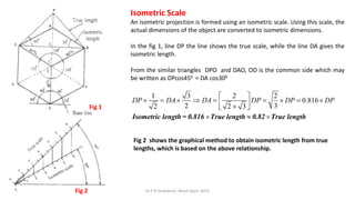
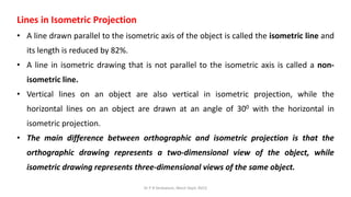
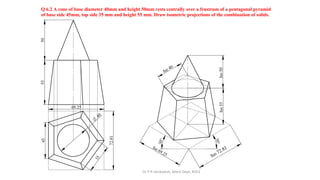
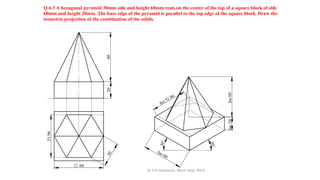
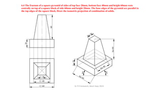
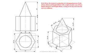
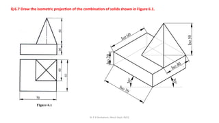
6.0 Isometric Projections (Using Solidworks)
SEMESTER: I/II
COURSE TITLE: COMPUTER AIDED ENGINEERING
GRAPHICS
COURSE CODE: 22MED13/23
Solution Manual
Prepared by :
Dr P R Venkatesh, Associate Professor
Room No 2, Ground Floor, Mech Engg Dept
RVCE, Bengaluru
Dr P R Venkatesh, Mech Dept, RVCE
What Is Isometric Projection?
• Isometric drawing, also commonly called isometric projection, is a
method of graphic representation of three-dimensional objects
through drawing.
• In isometric projection, the plan shows the three visible sides of the
object from the same angle to each other. Hence, the isometric
projection shows the sides of the object at an angle of 1200 to each
other. These lines of the object are called isometric axes.
• In isometric projection, two isometric axes are held at an angle of 300
with the horizontal plane. While the third axis forms an angle of 900
with the horizontal plane.
• Graphic representations of three-dimensional objects used by
engineers, technical illustrators, and architects are made using the
Isometric projection.
Dr P R Venkatesh, Mech Dept, RVCE
Isometric Scale
An isometric projection is formed using an isometric scale. Using this scale, the
actual dimensions of the object are converted to isometric dimensions.
In the fig 1, line DP the line shows the true scale, while the line DA gives the
isometric length.
From the similar triangles DPO and DAO, OD is the common side which may
be written as DPcos450 = DA cos300
Fig 2
Fig 1
1 3 2 2
0.816
2 3
2 2 3
DP DA DA DP DP DP
 
 =   = =  = 
 

 
  
Isometric length= 0.816 True length 0.82 True length
Fig 2 shows the graphical method to obtain isometric length from true
lengths, which is based on the above relationship.
Dr P R Venkatesh, Mech Dept, RVCE
Lines in Isometric Projection
• A line drawn parallel to the isometric axis of the object is called the isometric line and
its length is reduced by 82%.
• A line in isometric drawing that is not parallel to the isometric axis is called a non-
isometric line.
• Vertical lines on an object are also vertical in isometric projection, while the
horizontal lines on an object are drawn at an angle of 300 with the horizontal in
isometric projection.
• The main difference between orthographic and isometric projection is that the
orthographic drawing represents a two-dimensional view of the object, while
isometric drawing represents three-dimensional views of the same object.
Dr P R Venkatesh, Mech Dept, RVCE
The term "isometric" comes from the Greek for "equal measure", reflecting that the scale along each axis of the
projection is the same.
Isometric Projection of
circle.
The isometric projection
of a is an ellipse, whose
major axis is equal to
actual radius of the circle.
Dr P R Venkatesh, Mech Dept, RVCE
6.1 A regular pentagonal prism of base edge 30 mm and axis 60mm is mounted centrally over a
cylindrical block of 80 mm diameter and 25mm thick. Draw isometric projection of the combined solids.
Solution:
1. Draw the orthographic projections of the cylinder and pentagonal prism co axial with it.
2. Enclose the pentagonal prism in a rectangle (in top view) touching all corners and outer edges. This is to
obtain box which will be a rectangular prism whose height is equal to the length of axis of the prism.
3. However, the enclosure for a cylinder need not be shown as it will be a square prism with base side equal
to diameter of cylinder and height equal to length of axis of cylindrical block.
4. Obtain the isometric projection of cylindrical block using 4 center approximate method (to obtain
elliptical shape of the top & bottom faces in isometric projection)
5. Obtain the isometric projection of pentagonal prism by marking the corners of the pentagon w.r.t the
corners of the rectangular box and place it coaxially with the cylinder.
Note:
• To obtain isometric projection, enclose the given object in a box and tip the box on a corner such that
the horizontal edges of the box are at 300 and the vertical edges of the box remain vertical, but the
dimensions will be 82% of the true dimensions ( Scale ratio 0.816 can be used in solidworks). The
corners of the object must be marked w.r.t corners of the box.
X Y
VP
HP
3
0
O
80
25
60
3
0
°
3
0
°
46.17
48.54
6.1 A regular pentagonal prism of base edge 30 mm and axis 60mm is mounted centrally over a cylindrical block
of 80 mm diameter and 25mm thick. Draw isometric projection of the combined solids.
Iso 25
Iso 60
Iso 80
Iso 48.54
Iso 46.17
Dr P R Venkatesh, Mech Dept, RVCE
Note: 1. In isometric projections, outer visible edges must be thick, and the
hidden lines /curves must be thin.
2. Iso 80 means Isometric length of 80 = (0.816 x 80) = 65.28 mm and
so on.
Q 6.2 A cone of base diameter 40mm and height 50mm rests centrally over a frustrum of a pentagonal pyramid
of base side 45mm, top side 35 mm and height 55 mm. Draw isometric projections of the combination of solids.
3
5
O
40
55
50
3
0
°
3
0
°
72.81
Iso 72.81
69.25
Iso 69.25
Iso
55
Iso
50
Iso 40
45
Dr P R Venkatesh, Mech Dept, RVCE
Q 6.3 A hexagonal pyramid 30mm side and height 60mm rests on the center of the top of a square block of side
60mm and height 20mm. The base edge of the pyramid is parallel to the top edge of the square block. Draw the
isometric projection of the combination of the solids.
60
q
3
0
20
60
51.96
3
0
°
3
0
°
Iso 51.96
Iso
20
Iso
60
Iso 60
Dr P R Venkatesh, Mech Dept, RVCE
6.4 The frustum of a square pyramid of sides of top face 20mm, bottom face 40mm and height 60mm rests
centrally on top of a square block of side 60mm and height 20mm. The base edges of the pyramid are parallel to
the top edges of the square block. Draw the isometric projection of combination of solids.
60
q
40
q
20
q
20
60
3
0
°
3
0
°
Iso 60
Iso
20
Iso 40
Iso 20
Iso
60
Dr P R Venkatesh, Mech Dept, RVCE
Q 6.5 A sphere of diameter 60mm is placed centrally on the top face of a square
prism side 60mm and height 70mm. Draw the isometric projection of the
combination.
70
60
q
O
60
S
3
0
°
3
0
°
Iso
70
Iso 60
Iso
30
A sphere, will appear as a circle of actual radius when looked at any angle, and hence isometric
projection of a sphere will be a circle. However, the center to center height will be a vertical dimension
and hence it will be isometric length of the radius of sphere.
O 60
S
Dr P R Venkatesh, Mech Dept, RVCE
Q 6.6 Draw the isometric projection of a hexagonal prism of side
of base 40mm and height 60mm with a right circular cone of base
50mm diameter and height 60mm, resting on its top such that the
axes are collinear.
O
50
60
40
60
69.28
80
3
0
°
3
0
°
Iso
60
Iso 80
Iso
60
Iso 50
Dr P R Venkatesh, Mech Dept, RVCE
Q 6.7 Draw the isometric projection of the combination of solids shown in Figure 6.1.
Iso
20
3
0
°
3
0
°
Iso
50
Iso 70
Iso 60
Iso 40

5.Isometric Projections Solutions.pdf

  • 1.
    6.0 Isometric Projections(Using Solidworks) SEMESTER: I/II COURSE TITLE: COMPUTER AIDED ENGINEERING GRAPHICS COURSE CODE: 22MED13/23 Solution Manual Prepared by : Dr P R Venkatesh, Associate Professor Room No 2, Ground Floor, Mech Engg Dept RVCE, Bengaluru Dr P R Venkatesh, Mech Dept, RVCE
  • 2.
    Dr P RVenkatesh, Mech Dept, RVCE What Is Isometric Projection? • Isometric drawing, also commonly called isometric projection, is a method of graphic representation of three-dimensional objects through drawing. • In isometric projection, the plan shows the three visible sides of the object from the same angle to each other. Hence, the isometric projection shows the sides of the object at an angle of 1200 to each other. These lines of the object are called isometric axes. • In isometric projection, two isometric axes are held at an angle of 300 with the horizontal plane. While the third axis forms an angle of 900 with the horizontal plane. • Graphic representations of three-dimensional objects used by engineers, technical illustrators, and architects are made using the Isometric projection.
  • 3.
    Dr P RVenkatesh, Mech Dept, RVCE Isometric Scale An isometric projection is formed using an isometric scale. Using this scale, the actual dimensions of the object are converted to isometric dimensions. In the fig 1, line DP the line shows the true scale, while the line DA gives the isometric length. From the similar triangles DPO and DAO, OD is the common side which may be written as DPcos450 = DA cos300 Fig 2 Fig 1 1 3 2 2 0.816 2 3 2 2 3 DP DA DA DP DP DP    =   = =  =          Isometric length= 0.816 True length 0.82 True length Fig 2 shows the graphical method to obtain isometric length from true lengths, which is based on the above relationship.
  • 4.
    Dr P RVenkatesh, Mech Dept, RVCE Lines in Isometric Projection • A line drawn parallel to the isometric axis of the object is called the isometric line and its length is reduced by 82%. • A line in isometric drawing that is not parallel to the isometric axis is called a non- isometric line. • Vertical lines on an object are also vertical in isometric projection, while the horizontal lines on an object are drawn at an angle of 300 with the horizontal in isometric projection. • The main difference between orthographic and isometric projection is that the orthographic drawing represents a two-dimensional view of the object, while isometric drawing represents three-dimensional views of the same object.
  • 5.
    Dr P RVenkatesh, Mech Dept, RVCE The term "isometric" comes from the Greek for "equal measure", reflecting that the scale along each axis of the projection is the same. Isometric Projection of circle. The isometric projection of a is an ellipse, whose major axis is equal to actual radius of the circle.
  • 6.
    Dr P RVenkatesh, Mech Dept, RVCE 6.1 A regular pentagonal prism of base edge 30 mm and axis 60mm is mounted centrally over a cylindrical block of 80 mm diameter and 25mm thick. Draw isometric projection of the combined solids. Solution: 1. Draw the orthographic projections of the cylinder and pentagonal prism co axial with it. 2. Enclose the pentagonal prism in a rectangle (in top view) touching all corners and outer edges. This is to obtain box which will be a rectangular prism whose height is equal to the length of axis of the prism. 3. However, the enclosure for a cylinder need not be shown as it will be a square prism with base side equal to diameter of cylinder and height equal to length of axis of cylindrical block. 4. Obtain the isometric projection of cylindrical block using 4 center approximate method (to obtain elliptical shape of the top & bottom faces in isometric projection) 5. Obtain the isometric projection of pentagonal prism by marking the corners of the pentagon w.r.t the corners of the rectangular box and place it coaxially with the cylinder. Note: • To obtain isometric projection, enclose the given object in a box and tip the box on a corner such that the horizontal edges of the box are at 300 and the vertical edges of the box remain vertical, but the dimensions will be 82% of the true dimensions ( Scale ratio 0.816 can be used in solidworks). The corners of the object must be marked w.r.t corners of the box.
  • 7.
    X Y VP HP 3 0 O 80 25 60 3 0 ° 3 0 ° 46.17 48.54 6.1 Aregular pentagonal prism of base edge 30 mm and axis 60mm is mounted centrally over a cylindrical block of 80 mm diameter and 25mm thick. Draw isometric projection of the combined solids. Iso 25 Iso 60 Iso 80 Iso 48.54 Iso 46.17 Dr P R Venkatesh, Mech Dept, RVCE Note: 1. In isometric projections, outer visible edges must be thick, and the hidden lines /curves must be thin. 2. Iso 80 means Isometric length of 80 = (0.816 x 80) = 65.28 mm and so on.
  • 8.
    Q 6.2 Acone of base diameter 40mm and height 50mm rests centrally over a frustrum of a pentagonal pyramid of base side 45mm, top side 35 mm and height 55 mm. Draw isometric projections of the combination of solids. 3 5 O 40 55 50 3 0 ° 3 0 ° 72.81 Iso 72.81 69.25 Iso 69.25 Iso 55 Iso 50 Iso 40 45 Dr P R Venkatesh, Mech Dept, RVCE
  • 9.
    Q 6.3 Ahexagonal pyramid 30mm side and height 60mm rests on the center of the top of a square block of side 60mm and height 20mm. The base edge of the pyramid is parallel to the top edge of the square block. Draw the isometric projection of the combination of the solids. 60 q 3 0 20 60 51.96 3 0 ° 3 0 ° Iso 51.96 Iso 20 Iso 60 Iso 60 Dr P R Venkatesh, Mech Dept, RVCE
  • 10.
    6.4 The frustumof a square pyramid of sides of top face 20mm, bottom face 40mm and height 60mm rests centrally on top of a square block of side 60mm and height 20mm. The base edges of the pyramid are parallel to the top edges of the square block. Draw the isometric projection of combination of solids. 60 q 40 q 20 q 20 60 3 0 ° 3 0 ° Iso 60 Iso 20 Iso 40 Iso 20 Iso 60 Dr P R Venkatesh, Mech Dept, RVCE
  • 11.
    Q 6.5 Asphere of diameter 60mm is placed centrally on the top face of a square prism side 60mm and height 70mm. Draw the isometric projection of the combination. 70 60 q O 60 S 3 0 ° 3 0 ° Iso 70 Iso 60 Iso 30 A sphere, will appear as a circle of actual radius when looked at any angle, and hence isometric projection of a sphere will be a circle. However, the center to center height will be a vertical dimension and hence it will be isometric length of the radius of sphere. O 60 S Dr P R Venkatesh, Mech Dept, RVCE
  • 12.
    Q 6.6 Drawthe isometric projection of a hexagonal prism of side of base 40mm and height 60mm with a right circular cone of base 50mm diameter and height 60mm, resting on its top such that the axes are collinear. O 50 60 40 60 69.28 80 3 0 ° 3 0 ° Iso 60 Iso 80 Iso 60 Iso 50 Dr P R Venkatesh, Mech Dept, RVCE
  • 13.
    Dr P RVenkatesh, Mech Dept, RVCE Q 6.7 Draw the isometric projection of the combination of solids shown in Figure 6.1. Iso 20 3 0 ° 3 0 ° Iso 50 Iso 70 Iso 60 Iso 40