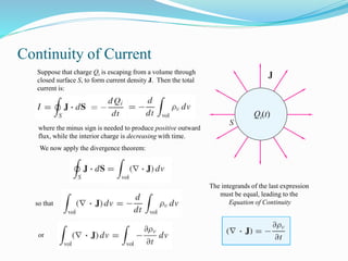
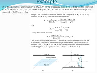
1. The document discusses conductors, dielectrics, current density, polarization, and electric susceptibility. It defines key concepts like current, current density, polarization field, dielectric constant, and boundary conditions for electric fields.
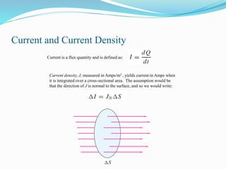
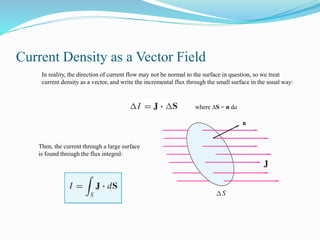
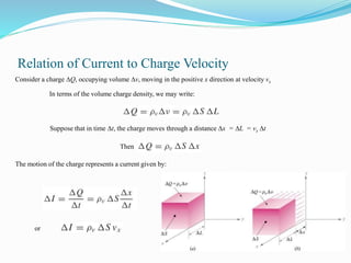
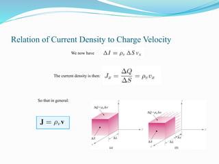
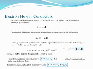
2. Conductors allow free electron flow while insulators have a large band gap; semiconductors have a small gap allowing electron excitation. Current density relates to charge velocity and conductivity.
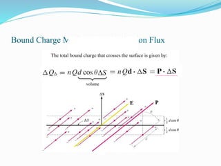
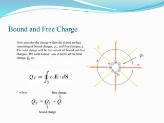
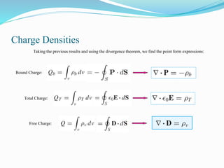
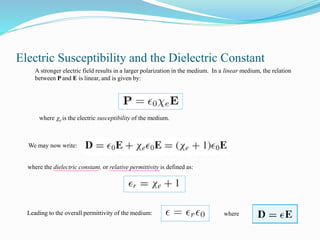
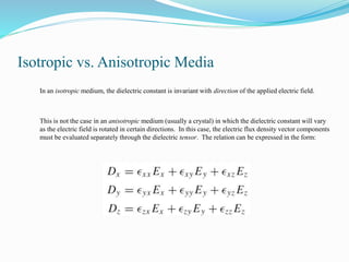
3. Dielectrics have bound electric dipoles that contribute to polarization. The polarization field depends on dipole density and alignment with the electric field. Boundary conditions require continuous tangential E and normal D fields.


![Polarization Field
[dipole moment/vol]
or
[C/m2]
v
The number of dipoles is
expressed as a density, n
dipoles per unit volume.
The Polarization Field of the
medium is defined as:](https://image.slidesharecdn.com/5chapter5currentdensity1-220830234042-58038d83/85/5-chapter-5_current-density-1-pptx-19-320.jpg)


![3. Electric charge and electric fields [12hrs].pptx](https://cdn.slidesharecdn.com/ss_thumbnails/3-250325125403-64ebc3f7-thumbnail.jpg?width=640&height=640&fit=bounds)


