Download to read offline
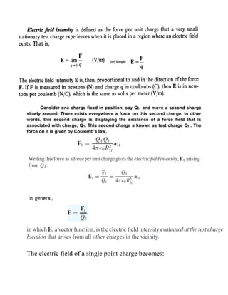
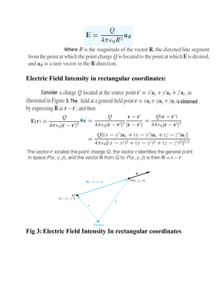
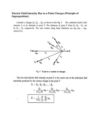
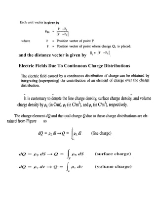
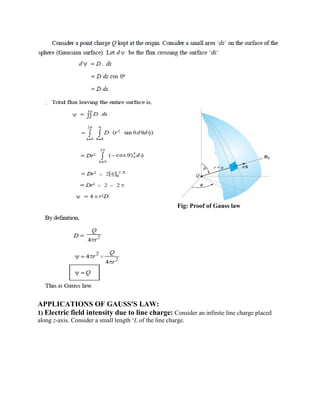
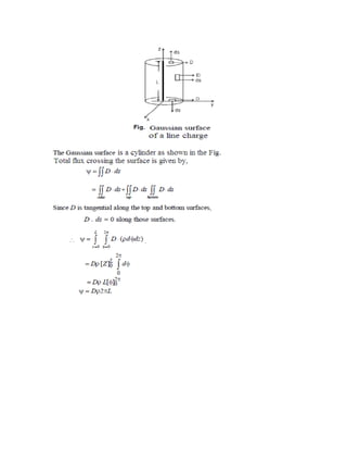
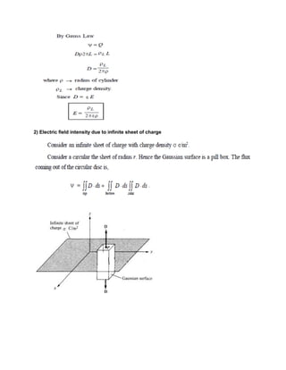
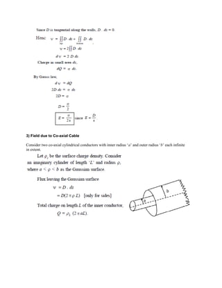
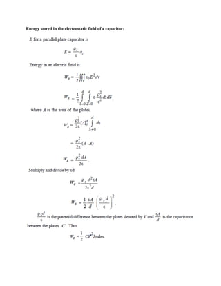
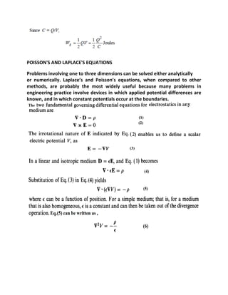
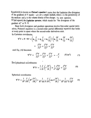
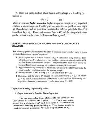

This document provides an overview of electrostatics. It defines key concepts like electric field, electric flux density, Gauss's law, capacitance, and more. Applications of electrostatics include electric power transmission, X-ray machines, solid-state electronics, medical devices, industrial processes, and agriculture. Coulomb's law describes the electric force between point charges. Gauss's law relates the electric flux through a closed surface to the enclosed charge. Capacitance is the ratio of stored charge on conductors to the potential difference between them.


